
Related Manuals for Leuze AMS 335i


Summary of Contents for Leuze AMS 335i
- Page 1 Original operating instructions AMS 335i Optical Laser Measurement System – CANopen We reserve the right to make technical changes EN 2021/04/30 - 50113356...
- Page 2 © 2021 Leuze electronic GmbH + Co. KG In der Braike 1 D-73277 Owen / Germany Phone: +49 7021 573-0 Fax: +49 7021 573-199 http://www.leuze.com info@leuze.de Leuze electronic GmbH + Co. KG AMS 335...
- Page 3 AMS 335 The main menus Device information - main menu AMS 335i 120 Leuze electronic This menu item contains detailed informa- tion on GmbH & Co. KG • Device type SW: V 1.3.0HW:1 • Manufacturer SN: ----------------------- • Software and hardware version •...
-
Page 4: Table Of Contents
Table of contents General information ..........5 Explanation of symbols . - Page 5 Table of contents Reflectors ........... . . 27 General information .
- Page 6 Table of contents 9.1.3 Stub cables (drop lines) ..........54 Address assignment .
- Page 7 Table of contents Maintenance ..........100 12.1 General maintenance information .
-
Page 8: General Information
Note! The Declaration of Conformity for these devices can be requested from the manufacturer. The manufacturer of the product, Leuze electronic GmbH & Co. KG in D-73277 Owen, possesses a certified quality assurance system in accordance with ISO 9001. Leuze electronic GmbH + Co. KG... -
Page 9: Description Of Functions Ams 335 I
With its AMS 3xx product series, Leuze makes available a wide range of internationally rele- vant interfaces. Note that each interface version listed below corresponds to a different AMS 3xx model. -
Page 10: Safety
Leuze electronic GmbH + Co. KG is not liable for damages caused by improper use. Read the technical description before commissioning the device. Knowledge of this ... -
Page 11: Competent Persons
Exemption of liability Leuze electronic GmbH + Co. KG is not liable in the following cases: • The device is not being used properly. • Reasonably foreseeable misuse is not taken into account. -
Page 12: Laser Safety Notices
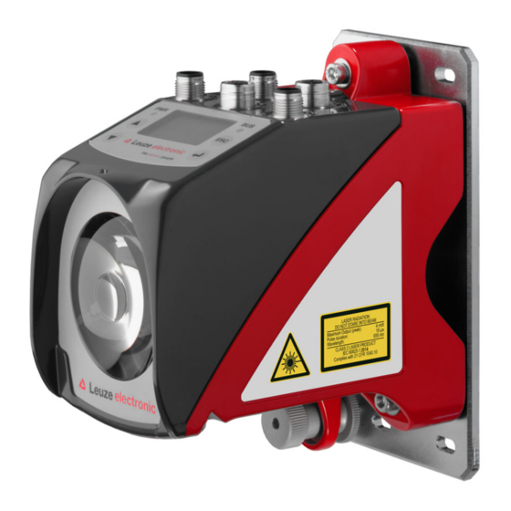
The device must not be tampered with and must not be changed in any way. There are no user-serviceable parts inside the device. Repairs must only be performed by Leuze electronic GmbH + Co. KG. NOTE Affix laser information and warning signs! Laser information and warning signs are attached to the device (see figure 2.1). - Page 13 Safety A Laser aperture B Laser warning sign C Laser information sign with laser parameters Figure 2.1: Laser apertures, laser warning signs AMS 335 Leuze electronic GmbH + Co. KG...
- Page 14 18 μs 18 μs Wavelength: 655 nm 655 nm CLASS 2 LASER PRODUCT IEC 60825-1:2014 Complies with 21 CFR 1040.10 IEC 60825-1:2014 Figure 2.2: Laser warning and information signs – supplied stick-on labels Leuze electronic GmbH + Co. KG AMS 335...
-
Page 15: Fast Commissioning / Operating Principle
Mounting the reflector The reflector is mounted using 4 screws (M5). The reflector is angled using the spacer sleeves included. Incline the reflector by approx. 1°. Detailed information can be found in Chapter 6.4. AMS 335 Leuze electronic GmbH + Co. KG... -
Page 16: Connecting The Voltage Supply
Install the EDS file that belongs to the AMS 335 …, in your planning tool/control (e.g. TwinCAT). Note! You can find the EDS file at www.leuze.com. The AMS 335 is configured in the planning tool/control by means of the EDS file. If the AMS 335... -
Page 17: Technical Data
0x00080196 (absolute linear encoder) Controls and indicators Keyboard 4 keys Display Monochromatic graphical display, 128 x 64 pixels 2 LEDs, two-colored Inputs/outputs Quantity 2, programmable Input Protected against polarity reversal Output Max. 60 mA, short-circuit-proof AMS 335 Leuze electronic GmbH + Co. KG... - Page 18 This is a Class A product. In a domestic environment this product may cause radio interference, in which case the operator may be required to take adequate measures. The AMS 335 is designed in accordance with protection class III for supply with PELV (protective extra-low voltage). Leuze electronic GmbH + Co. KG AMS 335...
-
Page 19: Ams 335 Dimensioned Drawing
M5 screw for alignment Knurled nut with WAF4 hexagon socket and M5 nut for securing Optical axis Zero point of the distance to be measured Figure 4.1: AMS 335 dimensioned drawing AMS 335 Leuze electronic GmbH + Co. KG... -
Page 20: Overview Of Ams 335 I Types
50113698 AMS 335 200 H 200m operating range, CANopen interface, integrated heating 50113699 AMS 335 300 H 300m operating range, CANopen interface, integrated heating 50113700 Table 4.1: Overview of AMS 335 types Leuze electronic GmbH + Co. KG AMS 335... -
Page 21: Installation And Mounting
Note! Please note that the shown name plate is for illustration purposes only; the contents do not correspond to the original. Save the original packaging for later storage or shipping. AMS 335 Leuze electronic GmbH + Co. KG... -
Page 22: Mounting The Ams 335 I
AMS 335 and the reflector. Use M5 screws to fasten the laser measurement system. Secure the screws with a lock washer to protect against loosening caused by vibrations. Leuze electronic GmbH + Co. KG AMS 335... - Page 23 ). Knurled nut and nut must not be tightened until alignment Figure 5.2 has been completed. Attention! The device must not be opened. Failure to comply will render the guarantee void. Warranted features cannot be guaranteed after the device has been opened. AMS 335 Leuze electronic GmbH + Co. KG...
-
Page 24: Optional Mounting Bracket
A mounting bracket for mounting the AMS 335 on a flat, horizontal surface is available as an optional accessory. Type designation: MW OMS/AMS 01 Part no.: 50107255 Laser beam Figure 5.3: Optional mounting bracket Leuze electronic GmbH + Co. KG AMS 335... -
Page 25: Parallel Mounting Of The Ams 335
Measurement distance up to 120m: minimum parallel spacing X ≥ 600mm Measurement distance up to 200m: minimum parallel spacing X ≥ 750mm Measurement distance up to 300m: minimum parallel spacing X ≥ 750mm AMS 335 Leuze electronic GmbH + Co. KG... -
Page 26: Parallel Mounting Of Ams 335 I And Ddls Optical Data Transmission
Depending on the size of the used reflector, the DDLS can be mounted with a minimum parallel spacing of 100mm to the AMS 335 . The parallel spacing is independent of the distance. Leuze electronic GmbH + Co. KG AMS 335... -
Page 27: Mounting The Ams 335 I With Laser Beam Deflector Unit
Use the M5 screws to mount the deflector unit. Secure the screws with a lock washer to protect against loosening caused by vibrations. Figure 5.5: Mounting variants of the US AMS 01 laser beam deflector unit AMS 335 Leuze electronic GmbH + Co. KG... -
Page 28: Dimensioned Drawing Of Us Ams 01 Deflector Unit
Installation and mounting 5.3.2 Dimensioned drawing of US AMS 01 deflector unit Laser beam Figure 5.6: Dimensioned drawing of US AMS 01 deflector unit Leuze electronic GmbH + Co. KG AMS 335... -
Page 29: Mounting The Us 1 Oms Deflector Unit Without Mounting Bracket
Height of the spring in non- preloaded state A Mirror Figure 5.7: Photo and dimensioned drawing of the US 1 OMS deflector unit The laser light spot is aligned with the reflector as described in Chapter 5.2. AMS 335 Leuze electronic GmbH + Co. KG... -
Page 30: Reflectors
Reflectors General information The AMS 335 measures distances against a reflective tape specified by Leuze. All technical data given for the AMS 335 , such as the operating range or accuracy, can only be achieved with the reflective tape specified by Leuze. -
Page 31: Technical Data Of Self-Adhesive Tape
Do not use any abrasive agents. A conventional household detergent Cleaning can be used as a cleaning agent. Rinse with clear water and dry the surface. Reflector storage Store in a cool and dry place. AMS 335 Leuze electronic GmbH + Co. KG... -
Page 32: Dimensioned Drawing Of Reflective Tape On Carrier Plate
Always align the TOP marking with the AMS connections! (Chapter 6.4.2) Figure 6.1: Dimensioned drawing of reflectors Article Reflective tape (mm) Reflector plate (mm) Reflective tape 200x200-M Reflective tape 500x500-M Reflective tape 914x914-M Leuze electronic GmbH + Co. KG AMS 335... -
Page 33: Technical Data Of Heated Reflectors
Do not use any abrasive agents. A conventional household Cleaning detergent can be used as a cleaning agent. Rinse with clear water and dry the surface. Reflector storage Store in a cool and dry place. AMS 335 Leuze electronic GmbH + Co. KG... -
Page 34: Dimensioned Drawing Of Heated Reflectors
XL ± 1 Si cable 3 x 0.75mm² Figure 6.2: Dimensioned drawing of heated reflectors Article Reflective tape (mm) Insulated carrier plate (mm) Reflective tape 200x200-H Reflective tape 500x500-H Reflective tape 914x914-H Leuze electronic GmbH + Co. KG AMS 335... -
Page 35: Selecting Reflector Size
Depending on the system design, the reflector can be mounted so that it moves with the vehicle or it can be mounted at a fixed location. Attention! The reflector sizes shown below are a recommendation from Leuze for on-vehicle mounting of the i. For stationary mounting of the... -
Page 36: Mounting The Reflector
For this purpose, use the alignment elements provided on the AMS 335 … (see chapter 5.2 "Mounting the AMS 335i"). If necessary, remove the protective film from the reflector. Attention! The "TOP" label on the reflectors should be aligned the same as the connections of the... - Page 37 Direct reflection due to the triple structure Deflected surface reflection due to the pitch of the reflective tape Figure 6.3: Mounting the reflector Pitch approx. 1° Spacer sleeves Figure 6.4: Pitch of the reflector AMS 335 Leuze electronic GmbH + Co. KG...
- Page 38 Direct reflection due to the triple structure Deflected surface reflection due to the pitch of the reflective tape Figure 6.5: Mounting of heated reflectors Pitch approx. 1° Spacer sleeves Figure 6.6: Pitch of the heated reflector Leuze electronic GmbH + Co. KG AMS 335...
-
Page 39: Table Of Reflector Pitches
Reliable operation of the and, thus, max. operating range and accuracy can only AMS 335 be achieved with the reflective tape specified by Leuze. Correct operation cannot be guar anteed if other reflectors are used! AMS 335 Leuze electronic GmbH + Co. KG... -
Page 40: Electrical Connection
The laser measurement systems are designed in accordance with protection class III for sup ply by PELV (protective extra-low voltage with reliable disconnection). Note! Degree of protection IP65 is achieved only if the connectors and caps are screwed into place! Leuze electronic GmbH + Co. KG AMS 335... -
Page 41: Pwr - Voltage Supply / Switching Input/Output
CAN_H Drain Shield CAN_L Not assigned Not assigned DRAIN CAN_H Data signal CAN_H CAN_L Data signal CAN_L M12 connector Thread Functional earth (housing) (A-coded) Table 7.2: Pin assignment for CANopen BUS IN AMS 335 Leuze electronic GmbH + Co. KG... -
Page 42: Canopen Bus Out
RS 232 receiving line/ RS232-RX RS232-RX service data M12 socket Not used (A-coded) Thread Functional earth (housing) Table 7.4: Pin assignment - Service Note! The service interface is designed only for use by Leuze! Leuze electronic GmbH + Co. KG AMS 335... -
Page 43: Display And Control Panel Ams 335I
Display and control panel AMS 335i Display and control panel AMS 335 Structure of the control panel Status indicator Bus/interface info Bar graph Distance measurement value Control buttons Figure 8.1: Structure of the control panel using the AMS 304 PROFIBUS device variant as... - Page 44 Display and control panel AMS 335i Warning - laser prefailure message: Laser diode old, device still functional, exchange or have repaired. Warning - temperature monitoring: Internal device temperature above/below permissible range. Plausibility error: Implausible measurement value. Possible causes: light beam interruption, outside of measurement range, permissible internal device temperature considerably exceeded or traverse rate >10m/s.
-
Page 45: Led Status Indicators
Display and control panel AMS 335i 8.2.2 LED status indicators PWR LED Device OFF - No supply voltage Flashing green Power LED flashes green - No measurement value output - Voltage connected - Self test running - Initialization running - Boot process running... -
Page 46: Control Buttons
Display and control panel AMS 335i Flashing green LED flashes green - "PRE-OPERATIONAL" state - "STOPPED" state Green continuous light LED is green - "OPERATIONAL" state Flashing red LED flashes red - Invalid configuration Red continuous light LED red - No bus connection... -
Page 47: Menu Description
Display and control panel AMS 335i Setting values If input of a value is possible, the display looks like this: Delete character Enter digit <-|0123456789 save Default ----------------- Unit Save Use the buttons to set the desired value. An accidental, incorrect entry can be corrected by selecting <-| and then pressing... -
Page 48: Parameter Menu
Display and control panel AMS 335i Status and measurement data - main menu IO1 LSR IO2 TMP ATT • Display of status, warning and error messages. • Status overview of the switching inputs/outputs • Bar graph for the received signal level. - Page 49 Position value submenu Note! The parameters named under position value are to be set via the EDS file of the AMS 335i. If parameters from the position value submenu are changed via the display, these may be overwritten via a startup sequence stored in the control.
- Page 50 Display and control panel AMS 335i Table 8.3: Position value submenu Level 3 Level 4 Level 5 Selection/configuration option Standard Description Unit Metric/Inch Metric Specifies the units of the measured distances Counting Positive/Negative Positive direction Positive: The measurement value begins at 0 and increases with increasing distance.
- Page 51 Display and control panel AMS 335i Table 8.4: I/O submenu Level 3 Level 4 Level 5 Selection/configuration option Standard Description Switching Function Pos. limit value 1 / Pos. limit value 2 / Velocity / Plausibility output Intensity (ATT) / Temp. (TMP) / Laser (LSR) /...
- Page 52 Service Baud rate 57.6kbit/s / 115.2kbit/s 115.2kbit/ RS232 The service interface is only available to Leuze personnel. Format 8,e,1 / 8,n,1 8,n,1 The service interface is only available to Leuze personnel. Leuze electronic GmbH + Co. KG AMS 335...
-
Page 53: Language Selection Menu
Display and control panel AMS 335i 8.3.3 Language selection menu Language selection o Deutsch English o Español o Français o Italiano 5 display languages are available: • German • English • Spanish • French • Italian The AMS 335 is delivered from the factory with the display preset to English. -
Page 54: Operation
Display and control panel AMS 335i Operation An operating process is described here using parameter enable as an example. Parameter enable During normal operation parameters can be viewed only. If parameters are to be changed, the ON menu item in the Parameter -> Parameter handling -> Parameter enable menu must be activated. - Page 55 Display and control panel AMS 335i Note! If a password was stored, parameter enable is not possible until this password is entered; see "Password for parameter enable" below. Password for parameter enable Parameter entry on the AMS 335 can be protected with a password. With the AMS 335 , the password is defined via the EDS file (class 100, instance 1).
-
Page 56: Canopen Interface
If the AMS 335 is the last participant in the trunk line, the trunk line can be terminated via the M12 BUS OUT connection. For this purpose, Leuze electronic offers an M12 terminating resistor, see chapter 11 "Type overview and accessories". -
Page 57: Stub Cables (Drop Lines)
The max. permissible length of a stub cable must not be exceeded. Taps and multi-taps permit a wide range of topologies. AMS 335 Leuze electronic GmbH + Co. KG... -
Page 58: Address Assignment
The address 0 is usually reserved for the CANopen master. Note! The "Layer Setting Services (LSS)" function is not supported by the AMS 335i. For this rea son, the address must be set manually via the display/panel of the AMS. -
Page 59: Baud Rate Setting
Bus Out of the AMS, these participants also remain active after activation of parameter enable. After cancelation of parameter enable, the AMS 335i is active again on the CANopen. AMS 335 Leuze electronic GmbH + Co. KG... -
Page 60: Canopen Electrical Connection
"Accessories – Terminating resistor" on page 97. Note! For connecting BUS IN and BUS OUT, we recommend our ready-made CANopen cables (see chapter 11.3.6 "Accessory ready-made cables for CANopen"). Leuze electronic GmbH + Co. KG AMS 335... -
Page 61: Communication Mechanisms Of Ams 335
The objects are uniquely identified using an index addressing scheme. The structure of the object directory, the assignment of the index numbers, as well as some mandatory entries are specified in the CIA standard DS301 for CANopen. AMS 335 Leuze electronic GmbH + Co. KG... -
Page 62: Eds File
Since there is no protocol structure in the telegram of a PDO, the participants in the network for whom these data are intended must know how the user data in the data area of the PDO are structured (which data are stored where in the user data area). Leuze electronic GmbH + Co. KG AMS 335... - Page 63 Heartbeat and guarding / life time are standard communication objects from the DS301 CANopen specification. The corresponding objects here are: - Heartbeat 1017 - Guarding / Life time factor 100C and 100D AMS 335 Leuze electronic GmbH + Co. KG...
-
Page 64: Default 11 Bit Identifier
1409 - 1535 581 - 5FF Send SDO 1100xxxxxxx 1537 - 1663 601 - 67F Receive SDO 1110xxxxxxx 1793 - 1919 701 - 77F NMT Error Control xxxxxxx = node address 1 - 127 Leuze electronic GmbH + Co. KG AMS 335... -
Page 65: Object Structure Of Ams 335
Overview of encoder-specific object area of AMS 335 Object address in hex Objects of AMS 335 from encoder profile DS406 Class 1 6000 Operating parameters 6004 Position value 6500 Operating status 6501 Measurement value resolution AMS 335 Leuze electronic GmbH + Co. KG... -
Page 66: Detailed Description Of Canopen-Specific Object Area
AMS 335 fails. Sub- Index Name Data type Access Value range Comment index (hex) (hex) Minimum Maximum Default Error reg- 1001 ister Data structure of object Comment Byte Error register Leuze electronic GmbH + Co. KG AMS 335... - Page 67 This object contains general specifications about the AMS 335 Sub- Index Name Data type Access Value range Comment index (hex) (hex) Minimum Maximum Default Manufacturer ID 1018 Vendor ID u 32 number Product Product desig- u 32 code nation AMS 335 Leuze electronic GmbH + Co. KG...
- Page 68 31 of the COB ID for the respective PDO to 1, setting the inhibit time to the desired time and then setting bit 31 back to 0 (= PDO valid). This applies to all 4 PDOs! Leuze electronic GmbH + Co. KG AMS 335...
- Page 69 1801 u 32 280h + Node ID for TPDO1 Transmis- 1 = cyclical + sion type synchronous Inhibit time u 16 1000 Inhibit time Reserve Event u 16 65535 Event timer timer AMS 335 Leuze electronic GmbH + Co. KG...
- Page 70 COB-ID 1803 u 32 380h + Node ID for TPDO1 Transmis- 254 = asynchro- sion type nous Inhibit time u 16 1000 Inhibit time Reserve Event u 16 1000 Event timer timer Leuze electronic GmbH + Co. KG AMS 335...
- Page 71 1804 u 32 480h + Node ID for TPDO1 Transmis- 1 = synchronous sion type + cyclical Inhibit time u 16 1000 Inhibit time Reserve Event u 16 65535 Event timer timer AMS 335 Leuze electronic GmbH + Co. KG...
-
Page 72: Ams 335 I -Specific Object Area
1 = Inch (in) Value 1 = 0.001 Value 2 = 0.01 Value 3 = 0.1 Resolution u 8 Value 4 = 1 Value 5 = 10 Value 6 = free resolution Leuze electronic GmbH + Co. KG AMS 335... - Page 73 The offset value is immediately active without any further release. Sub-index 06 Free resolution Free resolution in mm/1000 or inch/100000 depending on the selected unit. AMS 335 Leuze electronic GmbH + Co. KG...
- Page 74 The "Position limit value range 1" object defines a distance range with lower and upper limit. If the measured value is outside the configured range, the corresponding status bits are set in the objects 2050 2051 and 2060 Leuze electronic GmbH + Co. KG AMS 335...
- Page 75 2000 sub-index 02 and also applies to the velocity. If no change is made in object 2000 sub-index 02, the AMS 335 uses the default setting "metric". The sign of the velocity is dependent on the counting direction in object 2000 sub-index 04. AMS 335 Leuze electronic GmbH + Co. KG...
- Page 76 The check is always performed from position start to position end. For example, if the range start is "5500" and Leuze electronic GmbH + Co. KG AMS 335...
- Page 77 0 = Velocity above upper limit 1 = Velocity below lower limit Bit 1: Direction selection 0 = Velocity monitoring not direction-dependent 1 = Velocity monitoring direction-dependent Bit 2: Velocity monitoring 0 = Deactivated 1 = Activated AMS 335 Leuze electronic GmbH + Co. KG...
- Page 78 Bit 3 - Bit 7: Reserve 9.5.8.9 Object 2023 Configuration of velocity monitoring 3 Note! For further explanations regarding the position start and position end parameters, see chapter 9.5.8.7 "Object 2021h Configuration of velocity monitoring 1". Leuze electronic GmbH + Co. KG AMS 335...
- Page 79 Bit 3 - Bit 7: Reserve 9.5.8.10 Object 2024 Configuration of velocity monitoring 4 Note! For further explanations regarding the position start and position end parameters, see chapter 9.5.8.7 "Object 2021h Configuration of velocity monitoring 1". AMS 335 Leuze electronic GmbH + Co. KG...
- Page 80 Bit 3 - Bit 7: Reserve 9.5.8.11 Object 2025 Configuration of dynamic velocity monitoring Note! For further explanations regarding the position start and position end parameters, see chapter 9.5.8.7 "Object 2021h Configuration of velocity monitoring 1". Leuze electronic GmbH + Co. KG AMS 335...
- Page 81 Index Name Data type Access Value range Comment index (hex) (hex) Minimum Maximum Default Velocity 2026 u 16 See below status Bit 0: Velocity measurement error 0 = OK 1 = Error AMS 335 Leuze electronic GmbH + Co. KG...
- Page 82 Bit 11: Velocity comparison – limit value 4 0 = Comparison not active 1 = Comparison active Bit 12: Velocity comparison – dynamic limit value 0 = Comparison not active 1 = Comparison active Leuze electronic GmbH + Co. KG AMS 335...
- Page 83 If the velocity value is outside of the configured values, the output is set. The monitoring processes from objects 2021h to 2025h are "OR" linked to this bit. 0 = OFF 1 = ON AMS 335 Leuze electronic GmbH + Co. KG...
- Page 84 9.5.8.14 Object 2051 Configuration of I/O 2 Sub- Index Name Data type Access Value range Comment index (hex) (hex) Minimum Maximum Default 2051 I/O2 See below The settings in "bold" are the default settings Leuze electronic GmbH + Co. KG AMS 335...
- Page 85 0 = OFF 1 = ON Bit 12: Temperature monitoring (TMP) If the internal device temperature is outside the defined limit values, the output is set. 0 = OFF 1 = ON AMS 335 Leuze electronic GmbH + Co. KG...
- Page 86 • Monitoring of lower position limit value 2 • Monitoring of upper position limit value 2 • Intensity (ATT) • Temperature (TMP) • Laser (LSR) • Plausibility (PLB) In sub-index 02, the laser diode can be switched OFF/ON. Leuze electronic GmbH + Co. KG AMS 335...
- Page 87 1 = Preset active Bit 10: Preset teach (toggle bit) This bit toggles with each teach event of a preset value Bit 11 - Bit 12: Reserve 0 = Reserve 1 = NC AMS 335 Leuze electronic GmbH + Co. KG...
- Page 88 ON/OFF Position Error message error mes- 1000 delay time in ms sage delay Velocity value in case of See below failure and error delay ON/OFF Error delay time 1000 (velocity) Leuze electronic GmbH + Co. KG AMS 335...
- Page 89 Name Data type Access Value range Comment index (hex) (hex) Minimum Maximum Default 0 = English Display 1 = German 2300 language 2 = Italian selection 3 = Spanish 4 = French AMS 335 Leuze electronic GmbH + Co. KG...
-
Page 90: Objects Of Ams 335 I From Encoder Profile Ds406 Class 1
For Class 1, it is essential to describe the following objects. 9.5.9.1 Object 6000 Operating parameter Sub- Index Name Data type Access Value range Comment index (hex) (hex) Minimum Maximum Default Operating 0= Positive 6000 parame- counting direc- ters tion, see below Leuze electronic GmbH + Co. KG AMS 335... - Page 91 Display of operating status from object 6000 Sub- Index Name Data type Access Value range Comment index (hex) (hex) Minimum Maximum Default Operating 6500 parame- See below ters Bit 0 - Bit 2 Not used AMS 335 Leuze electronic GmbH + Co. KG...
- Page 92 If the default resolution of 1 mm is set in object 2000 , the resolution is converted to the value 1 000 000 for object 6501. (1 000 000 x 1/1 000 000 = 1). Leuze electronic GmbH + Co. KG AMS 335...
-
Page 93: Diagnostics And Troubleshooting
(always "1" because no summation occurs) The status messages within the ring memory are selected with the up/down buttons Use the enter button to call up detailed information about the respective status message: AMS 335 Leuze electronic GmbH + Co. KG... -
Page 94: 10.1.2 Diagnosis
Use the up/down buttons to scroll in the bottom half between various displays. The contents of the scrollable pages are intended solely for Leuze for internal evaluation. The diagnostics have no influence on communication with the host interface and can be acti- vated during operation of the AMS 335 10.1.3 Expanded diagnosis... -
Page 95: General Causes Of Errors
Plausibility error Traverse rate >10m/s. Hardware error For error description, see display, PWR LED "static red" It may be necessary to send in the device. Table 10.1: General causes of errors AMS 335 Leuze electronic GmbH + Co. KG... -
Page 96: Interface Errors
Send in device at next possible opportunity to have laser diode replaced. Have replace- Laser diode warning ment device ready. Indicates an uncorrectable error in the Send in device for repair. Hardware error hardware Leuze electronic GmbH + Co. KG AMS 335... - Page 97 • Reason for requesting support together with a description For this purpose, please register the merchandise concerned. Simply register return of the merchandise on our website www.leuze.com under Contact & Support -> Repair Service & Returns: To ensure quick and easy processing of your request, we will send you a returns order with the returns address in digital form.
-
Page 98: Type Overview And Accessories
50113698 AMS 335 200 H 200m operating range, CANopen interface, integrated heating 50113699 AMS 335 300 H 300m operating range, CANopen interface, integrated heating 50113700 Table 11.1: Overview of AMS 335 types Leuze electronic GmbH + Co. KG AMS 335... -
Page 99: Overview Of Reflector Types
M12 connector, A-coded socket, 5-pin, BUS IN 50040097 KD 01-5-SA M12 connector, A-coded connector, 5-pin, BUS OUT 50040098 KD 095-5A M12 connector, A-coded socket, 5-pin, Power (PWR) 50020501 Table 11.5: Accessories – M12 connector AMS 335 Leuze electronic GmbH + Co. KG... -
Page 100: 11.3.4 Accessories - Terminating Resistor
Part no. K-D M12A-5P-5m- M12 socket, A-coded, axial connector outlet, open cable end, 50104557 cable length 5m K-D M12A-5P-10m- M12 socket, A-coded, axial connector outlet, open cable end, 50104559 cable length 10m Leuze electronic GmbH + Co. KG AMS 335... -
Page 101: 11.3.6 Accessory Ready-Made Cables For Canopen
In idle state: -40°C … +80°C In motion: -5°C … +80°C Material The cables comply with the CANopen requirements, Free of halogens, silicone and PVC Bending radius > 80mm, suitable for drag chains AMS 335 Leuze electronic GmbH + Co. KG... - Page 102 1m KB DN/CAN-2000- M12 connector + M12 socket for CANopen, axial connectors, 50114694 cable length 2m KB DN/CAN-5000- M12 connector + M12 socket for CANopen, axial connectors, 50114698 cable length 5m Leuze electronic GmbH + Co. KG AMS 335...
- Page 103 Contact your Leuze distributor or service organization should repairs be required. The addresses can be found on the inside of the cover and on the back. Note! When sending laser measurement systems to Leuze for repair, please provide an accurate description of the fault. 12.3 Disassembling, packing, disposing Repacking For later reuse, the device is to be packed so that it is protected.
- Page 104 EDS file ......13 Electrical connection ....37 Leuze electronic GmbH + Co. KG AMS 335...
- Page 105 ERR ......93 PLB ......93 AMS 335 Leuze electronic GmbH + Co. KG...
- Page 106 Menu structure AMS 335 Level 1 Level 2 Level 3 Level 4 Level 5 Selection/configuration option Detailed infor- mation on : Selection : Selection : Selection : Selection : Selection : Selection : Back : Back : Back : Back : Activate : Back Device information...
- Page 107 Deutsch / English / Español / Français / Italiano Page 50 Service Status messages Number of readings, reading gates, reading rate / non-reading rate etc. Page 50 Diagnosis Only for use by Leuze personnel for service purposes Expanded diagnosis Only for use by Leuze personnel for service purposes...
Need help?
Do you have a question about the AMS 335i and is the answer not in the manual?
Questions and answers