Advertisement
Quick Links
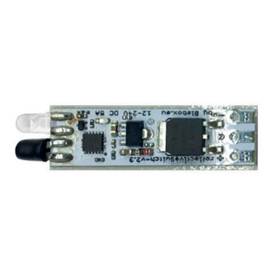
WORLD'S SMALLEST REFLECTVE LED CONTROLLER
SAFETY RULES
Do not connect the device to loads exceeding the permitted
values.
Connect only in accordance with the diagram presented in the
manual. Improper connections may be dangerous, it can damage
the controller, and loss of the warranty.
the outputs may be live. All assembly work should be ALWAYS
performed with the disconnected power circuit.
Connecting the device to a power supply that does not meet the
EN 60950 will invalidate the warranty.
CONNECTION DIAGRAM
+
OUT
reflectiveswitch
_
Attention! When soldering the wires be careful not
to overheat the controller board.
1
Before installing the controller, disconnect the voltage in the supplied circuit.
Remember that all assembly work should be carried out with the power
supply disconnected.
The controller should be mounted in a place protected from adverse environ-
or in the interior of the transparent housing of the controlled device. It is
advisable that the device is mounted in a stable and stationary position.
Familiarize yourself with the diagram and then proceed with the assembly of
the controller. Pay special attention to the designation of the controller
connectors. Start by connecting the power wires: (+) (red or black with a white
dotted line) and (-) (black).
Connect (paying attention to polarity) the LED strip. The device is equipped
with a strip of adhesive tape on the underside. Before sticking the controller,
glue it in the chosen place and hold for a few seconds. When choosing
a mounting location, remember that the sensor in the front of the device
should be placed at a distance of 3-20 mm from the detected element (eg
cabinet door or drawer wall).
If the moving surface is dark, it is advisable to stick a piece
of white sticker on it to improve the detection range of the
controller.
Connect the device to the power supply and check that the device correctly
detects the movable element.
LED STRIP
+
12 VD DC
power
supply
110 / 230V
INSTALLATION
2
1.
the default, as a mono-stable switch
strip when an object is detected. This mode is useful, for example, in
a cabinet that turns on the light when the door opens
2.
mono-stable, switching on the LED strip when an object is detected,
e.g. mounted in a door frame, switching on the lighting only when the
sliding door is fully separated
3.
bi-stable - applicable, for example, as a proximity switch, allowing you
the photo frame
3
To change the work mode, perform the following steps:
a)
Unplug the power supply for 10 seconds and then connect it again.
b)
LED lighting will blink, it means the status will change). Repeat the
action 10 times in a maximum of 15 seconds being connected to the
supply source.
10 x / 15 seconds
The 5 times fast blinking of the connected LED lighting informs
that the programming mode has been entered correctly:
the controller will inform about the selected mode
through the blinking sequence (starts from 1): Mode 1
- sequence of 1 blink, Mode 2 - sequence of 2 blinks,
Mode 3 - sequence of 3 blinks
c)
1 x
the controller will inform about the selected mode
through the blinking sequence: Mode 1 - sequence of 1
blink, Mode 2 - sequence of 2 blinks, Mode 3 - sequence
of 3 blinks
After the blinking sequence is repeated three times, the controller
will select that mode.
5 times the fast blinking of the connected LED lighting, informs
that it has successfully left the programming mode:
MODE SETTINGS
CHANGE OF MODE
Advertisement

Related Manuals for BleBox ReflectiveSwitch


Summary of Contents for BleBox ReflectiveSwitch
- Page 1 CONNECTION DIAGRAM To change the work mode, perform the following steps: LED STRIP reflectiveswitch Unplug the power supply for 10 seconds and then connect it again. 12 VD DC LED lighting will blink, it means the status will change). Repeat the...
- Page 2 34 x 10 x 3 mm sensor protection level IP00 mounting method controller from -10 to + 40°C operating temperature for more information visit our website www.blebox.eu or send us an email to: info@blebox.eu support is available at support@blebox.eu...
Need help?
Do you have a question about the ReflectiveSwitch and is the answer not in the manual?
Questions and answers