Table of Contents
Advertisement
Quick Links
Advertisement
Table of Contents

Related Manuals for Blastrac 200VMB


Summary of Contents for Blastrac 200VMB
- Page 1 Original instructions in English OPERATING INSTRUCTIONS 200VMB VERSION 1.2...
- Page 2 Inspection comments Inspection before initial operation on: __________________________________________ __________________________________________ Date of initial operation: __________________________________________ Serial number & Year of manufacture: __________________________ _____________ Recurring inspections / maintenance log Date / Hour counter Findings Repairs / Cleaning Test *Competent person...
-
Page 3: Table Of Contents
Table of contents 1. Introduction 2. Machine description 3. Safety Work area safety Electrical safety Personal safety Machine safety Shot / steel blasting safety Maintenance safety Dust collector safety Transport safety Markings on the machine & EU Declaration 4. Before operation Daily check points of power supply Daily check points of machine Check points on the hoisting and lifting equipment... -
Page 4: Introduction
The Blastrac 200DC filter unit must be connected to the machine in order to separate the dust from the abrasive. This specially designed dust collection system ensures dust-free operation of the machine and clean air at the workspace. -
Page 5: Safety
Electrical cables must be rolled entirely off of the reels. c) Any damage to the electric cables and/or electrical components is not permitted. d) If the power supply cable or plug is damaged, it must be replaced immediately. Only use original Blastrac parts. -
Page 6: Personal Safety
The machine, specially the handle grip(s) must be free of fats/oils and has to be dry. All repair work has to be done by qualified Blastrac personnel, this guarantees a safe and reliable machine. k) Always use original Blastrac spare parts and abrasive. This will ensure the best performance. -
Page 7: Shot/Steelblasting Safety
Only use approved steel cables in appropriate condition. Using any other steel cable voids all warranty claims against Blastrac BV. Check points on the hoisting and lifting equipment h) Inspect the cables, rigging, spreader beam, winch motors or any other lifting device for damages before every use. -
Page 8: Dust Collector Safety
Dust collector safety by the machine a) Always use an appropriate Blastrac dust collector to ensure a dust-free operation of the machine and clean air at the workspace. Also the airflow helps to cool the machine and prevents overheating. -
Page 9: Markings On The Machine & Eu Declaration
Markings on the machine The following stickers are placed on the machine. Meanings of these symbols are: Wear a dust mask class FFP2 or ! Danger Hazardous voltage in motor higher. even when solid state controller is OFF. Disconnect main power before servicing motor, controller or associated wiring. -
Page 10: Before Operation
4. Before operation Before using the machine it is of great importance to inspect the machine. It is not permitted to use the machine if the machine safety is not according the checkpoints below. Daily check points power supply Use only extension cables for extending the main cable that are sized and marked in accordance with ... -
Page 11: Operating
5. Operating During operating the 200-VMB, the following additional safety instructions must be followed closely. Before switching on the machine make sure that no-one can be endangered when the machine starts up. Make sure that no vehicles, such as forklift trucks and other equipment run over the electric cable and the dust hose. -
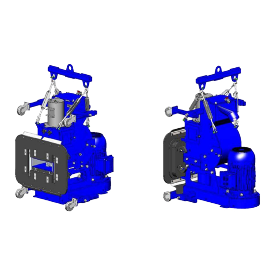
Page 12: Adjusting The Spreader Beam, Turnbuckles And Swivel Castors
Connect the central lifting point to the hoisting equipment. IMPORTANT! Make sure the hoisting equipment (such as cables, chains, winch, etc.) being used have a work load limit of at least 340 kg! IMPORTANT! The attachment point or rigging should have the capacity to handle 340 kg + the weight of the winch + the weight of the cable / chains! The machine itself weighs only 177 kg, but you also have to take in... -
Page 13: Switch On The Machine
Switch on the machine Before switching on the blast machine, switch on the dustcollector 200DC. If the underpressure is OK, indicator (#8) will light up green. Lift the machine a little bit above the ground and allow it to suck to the wall. The WALL SENSOR OK indicator (#7) will light up green. -
Page 14: Switch Off The Machine
Switch off the machine Close the abrasive valve (#9). Switch off the blast motor (#2). Lower the machine to the ground or on a pallet. Switch the main switch on the electrobox too position “OFF”. Pull out the connector of the mains power supply of the electrobox. - Page 15 Correct cage opening position The following 5 factors affect the blast pattern: The turning direction of the blast wheel must correspond to the instructions on the housing (arrow indicating the correct turning direction). With increased wear of the wear parts (Blastwheel, mouth seal, control cage) the blast pattern will change. ...
-
Page 16: Maintenance
Pay attention to unusual noises or strong vibrations. Check for the cause of every big change. Call a technician if you have doubts about the cause or when a repair without a technician seems not possible without damages. Only use genuine Blastrac spare parts. Our specialists will be happy to assist you with more advice. - Page 17 Remove the abrasive out of the abrasive storage hopper. All repair work must to be done by qualified Blastrac personnel, this to guarantee a safe and reliable machine. Any guarantee on the machine is expired when: Non original Blastrac parts have been used ...
-
Page 18: Changing The Mouth Seal Complete
Changing the mouth seal complete Pull off all 4 rubber springs from the threaded ends. Remove mouth seal complete from the housing. Assembly of a mouth seal complete Be sure that all rubber plates are in one line. If plates are not mounted in one line, the mouth seal will not move easy back and forwards. -
Page 19: Changing The Blastwheel
Changing the blastwheel Remove 2x M10 nuts so the abrasive valve can be lifted out of the machine. Remove all abrasive and clean the blastwheel with air. - Page 20 Block the blastwheel and loosen the central fixing bolt. Remove the blastwheel. ALWAYS use a new central fixing bolt when mounting a new blastwheel. (M10x35 Sockethead cap 12.9 + M10 washer) Order Blastrac Tune-up kit B20536K.
-
Page 21: Removing The Liners
Removing the liners Remove the M10 nuts of the Sideliner press strip Remove the M10 nuts of the Rebound liner cover plate Remove the Sideliner press strip on the other side of the machine 1. Use an air pistol to blow out all dust and dirt between the blasthousing and the rebound liner. Spray WD40 between the blasthousing and rebound liner. - Page 22 2. Use a brass drift to tap out the side liners...
-
Page 24: Abrasive Valve Maintenance 50 Hours
Abrasive valve maintenance 50 hours It is very important to keep the abrasive valve in good condition. Inspect and clean it regularly. Replace the E10447 Valve seal every +/- 50 hours. Remove the abrasive valve by loosening 2x M10 nuts and lift the valve out the machine. -
Page 25: Abrasive Valve Maintenance 250 Hours
Abrasive valve maintenance 250 hours The abrasive valve should be overhauled every +/-250 hours. 1. Remove the abrasive valve by loosening 2x M10 nuts and lift the valve out the machine. 2. Remove 2x M8x16 sockethead cap bolts and remove the “Dust plate” (E10457). 3. -
Page 26: The V-Belt
The V-belt The V-belt drives are designed for the installed driving power. To force a higher output through an excessive high tension of the V-belts will result in broken belts, damage to the bearings and causes loss of the total efficiency. -
Page 27: V-Belt Tension
V-belt tension The correct V-belt tension is of utmost importance in order to obtain a perfect power transmission and to reach the usual working life of the V-belt. Too low or to high tension causes frequently a premature breakdown of the V-belt. -
Page 28: Safety Check By A Competent Person
Loosen 7x M8x30 Sockethead cap and remove the E10440 “Belt cover”. Loosen 4x M12 nut to loosen the motor. Loosen the M12 nut to release the belt tension. Replace E01938 “V belt 1280”. Safety check by a competent person Safety checks of the hoisting equipment must be carried out at least once a year by a certified specialist. -
Page 29: Ammeter Digital Display
6.10 Ammeter digital display Selecting the displayed value By pressing the right key, the display can be switched between the current, min., or max. value. Pressing the right key once the current function („Act“, „Min“ or „Max“) is displayed for 2 seconds. If within this period the right key is pressed again, the current function is changed. -
Page 30: Troubleshooting
Check for other causes of air leakage. Abrasive loss on the Worn magnetic or rubber seals. Replace the magnetic and/or rubber seals. surface or escaping abrasive at the blast head Poor abrasive quality. Contact Blastrac. - Page 31 Check and clean the dust hose Ripped or damaged dust hose Replace dust hose Excessive wear in blast Wrong abrasive. Contact Blastrac. housing and rebound plenum The thrown abrasive blasts the housing Incorrect setting of the control cage and not the surface to be blasted. Adjust the blast pattern.
-
Page 32: Selection Of Abrasive
The Blastrac blast cleaning machines are designed and built to operate with Blastrac abrasive. Blastrac abrasive has a very high quality and has the rebouncing ability required for the efficient use of the machine. The selection of abrasive is very important since this is the material to carry out the surface treatment. -
Page 33: Technical Data
Noise level (under load) 90dB(A) Dust hose connection Ø100 mm Recommended filter unit 200DC The electrical diagrams of the electrical system are placed inside of the control panel. Design and specifications are subject to change without notice by Blastrac BV. - Page 34 Despite the fact that this guide is made with care, Blastrac takes no liability for errors in the manual and the possible consequences. We are naturally very interested in your findings and additions.
- Page 35 BLASTRAC EUROPE WE’RE READY TO ASSIST YOU! BLASTRAC THE NETHERLANDS BLASTRAC POLAND BLASTRAC FRANCE EUROPEAN HEAD OFFICE SALES & SERVICE CENTRE SALES & SERVICE CENTRE Utrechthaven 12 Golina, ul. Dworcowa 47E ZI - 29, Av. des Temps Modernes NL - 3433 PN Nieuwegein...
Need help?
Do you have a question about the 200VMB and is the answer not in the manual?
Questions and answers