Table of Contents
Advertisement
Quick Links
Advertisement
Table of Contents

Related Manuals for BUSCH SIMPLEX


Summary of Contents for BUSCH SIMPLEX
- Page 1 Operating instructions SIMPLEX Vacuum systems VD 0025 G – 0063 G – 0100 G Dr.-Ing. K. Busch GmbH Schauinslandstraße 1 79689 Maulburg Germany 0870169324/-0006_en / Translation of the original operating instructions / Subject to change without notice 16.11.2021...
- Page 2 0870169324_VD 0025‐0100G_‐0006_IM_en 2 / 46 ...
-
Page 3: Table Of Contents
1 | Contents Contents 1.1 Table of contents Contents ..................... 3 Table of contents ......................... 3 Register of tables ......................... 5 Register of illustrations ........................ 5 Safety ....................6 Safety devices ..........................6 Emergency information ....................... 6 Product description ................7 View vacuum system VD ...................... - Page 4 1 | Contents Troubleshooting ................27 General faults ..........................27 Failure table and measures ....................... 28 Spare parts and accessories ...............30 10.1 Spare parts ..........................30 Repair ....................31 Decommissioning and disposal ............32 12.1 Stop operating vacuum system ....................32 12.2 Disassembly and disposal ......................32 Dimensions sheets ................33 Connection values of the vacuum system VD ........39 14.1...
-
Page 5: Register Of Tables
1 | Contents 1.2 Register of tables Tab. 1: Connections vacuum system VD 0025 G AAA TAXX ........33 Tab. 2: Connections vacuum system VD 0025 G AAA TAAX (mobile) ......34 Tab. 3: Connections vacuum system VD 0063 G AAA TCXX ........35 Tab. -
Page 6: Safety
2 | Safety Safety Before commissioning of the vacuum system, read these operating instructions with care. Please contact your contact person from Busch if there are any questions. Keep the operating instructions so that you can use them for reference at a later time if nec‐ essary. These operating instructions remain valid as long as the customer does not make any changes to the product. The vacuum system is intended for industrial use. It must only be operated by technically trained specialists. Always wear personal protective equipment in accordance with local regulations. The vacuum system has been designed and produced according to state‐of‐the‐art methods. Nevertheless, a residual risk remains in operation. Potential dangers are highlighted in these operating instructions. Safety and warning notes are marked as follows, with the words DAN‐ GER, WARNING, CAUTION, ATTENTION and NOTE: DANGER ... Indicates a threatening hazard. Failure to observe safety instructions will result in death or serious injury. WARNING ... Indicates a potential hazard. Failure to observe safety instructions may result in death or se‐ rious injury. CAUTION ... Indicates a potential hazard. Failure to observe safety instructions may result in slight inju‐ ry. ATTENTION! ... Indicates a potential hazard. Failure to observe safety instructions may result in property damage. NOTICE ... Indicates helpful advice and recommendations as well as information for efficient and smooth operation. 2.1 Safety devices The motor of the rotary vane vacuum pump is safeguarded by a motor protection switch. If an ... -
Page 7: Product Description
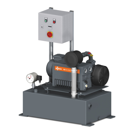
3 | Product description Product description 3.1 View vacuum system VD IN Gas inlet CC Switch and control cabinet OUT Gas outlet AF Air filter INO Gas inlet (optional) VV Venting valve RVP Rotary vane vacuum pump RA CPG Contact vacuum gauge NP Name plate VST Vacuum vessel Fig. 1: View vacuum system VD 0870169324_VD 0025‐0100G_‐0006_IM_en 7 / 46 ... -
Page 8: View Of The Rotary Vane Vacuum Pump R5 Ra
DA Rotation direction arrow motor OFP Oil fill plug EF Exhaust filter OSG Oil sight glass NP Name plate ODP Oil drain plug OF Oil filter EB Eye bolt AF Axial fan GB Gas ballast valve OS Oil separator Fig. 2: View rotary vane vacuum pump type R5 RA (0025 F) 3.3 Setup The vacuum system SIMPLEX VD comprises of a single‐stage rotary vane vacuum pump type R5 RA. The vacuum pump is mounted on a vacuum vessel. The intake‐side air filter and the strainer installed in the suction flange prevent the ingression of dirt particles in the vacuum pump. The gas ballast valve is used for the addition of a limited quantity of ambient air to the pro‐ cess gas, to counteract the condensation of vapor in the vacuum pump. In the vacuum vessel is a contact vacuum gauge installed for the 2‐point control which dis‐ plays the pressure in the vacuum vessel. The vacuum system is completely piped and the electrical components are wired on a switch and control cabinet. The vacuum system is also available as a mobile version on a push bar cart with four rolls. 0870169324_VD 0025‐0100G_‐0006_IM_en 8 / 46 ... -
Page 9: Function Principle
3.4 Function principle 3.4.1 Vacuum system VD Gas delivery from the vacuum vessel is effected by the single‐stage rotary vane vacuum pump. Pressure gas is exhausted against the atmosphere. The target values are set to the desired switch‐on and switch‐off values on the contact vacu‐ um gauge on the vacuum vessel. When the lower switching point is reached, the vacuum pump is switched off. When the vacuum in the vacuum vessel is used up, the pressure in the vessel increases and when the upper switching point is reached, the vacuum pump is switched on again and evacuates the vacuum vessel. 3.4.2 Rotary vane vacuum pump R5 RA Fig. 3: Operating principle of the rotary vane vacuum pump R5 RA The vacuum pump R5 RA works according to the rotary vane principle. The oil seals the spaces, lubricates the sliders and discharges the compression heat. The oil fil‐ ter cleans the circulating oil. Then the exhaust filters separate the oil from the discharged gas. 3.4.3 Gas ballast valve The vacuum pump is equipped with a gas ballast valve. The gas ballast valve is used for the addition of a limited quantity of ambient air to the process gas, to counteract the condensa‐ tion of vapor in the vacuum pump. The gas ballast valve reduces the final pressure of the vac‐ uum pump, see “Technical data” in chap. 15. 3.5 Intended use The vacuum system was designed for conveying air and other dry, non‐aggressive, non‐toxic and non‐explosive gases. Conveying any other media leads to increased thermal and/or mechanical stress of the vacu‐ um system and is only permitted in coordination with Busch. The vacuum system is designed for operation in a non‐hazardous area. The vacuum system can be operated continuously at final pressure and is suitable for continuous operation. The permitted ambiance conditions can be found in the technical data (chap. 15). The vacuum system is designed for indoor use; for outdoor installation, contact Busch to make special arrangements if necessary. 0870169324_VD 0025‐0100G_‐0006_IM_en 9 / 46 ... -
Page 10: Transport
4 | Transport Transport WARNING Danger of severe injury! Suspended load. • Never walk, stand or work below suspended loads. WARNING Hazard from vacuum system falling or tipping over! The weight of the vacuum system can kill a person or cause severe crushing. • Use a pallet appropriate to the weight and size of the system on which it can be moved by a forklift truck. Or lift the vacuum system using slings and suitable lifting gears with a fork‐ lift or lift truck to move it or remove the pallet. • Take care to avoid strain on the pipe work and vacuum pumps while placing the slings. • Observe the center of gravity and the lifting points; these are indicated in the scale draw‐ ings, see chap. 13. ATTENTION! Damage to the vacuum system! The vacuum system is already filled with oil at delivery. • Drain the oil before transport if transport in horizontal orientation is not possible. The vacuum system is packed in a wooden crate. It protects the system from damage during transport. The vacuum system is packed in a wooden structure and can be moved using a forklift. Unpack the vacuum system as near to the installation site as possible. Check scope of delivery for completeness. Check the vacuum system for transport damage. Dispose of packing material as required by current regulations. ... - Page 11 4 | Transport WARNING Danger of severe injury! Lift the vacuum system by devices of the individual components. • Do not lift the vacuum system by devices of the individual components, e.g. the vacuum pump, motor, etc. • Only lift the vacuum system as presented. Fig. 4: Transport of the vacuum system Screw four M10 eye bolts (not included in the scope of delivery) into the holes on the feet of the vacuum vessel (see fig. 4). Pass slings through the openings of the eye bolts and thus lift the vacuum system with a crane or a forklift. 0870169324_VD 0025‐0100G_‐0006_IM_en 11 / 46 ...
- Page 12 4 | Transport The vacuum pump can be lifted by the eye bolts. WARNING Danger of severe injury! Suspended load. • Never walk, stand and work below suspended loads! • The eye bolts (EB) must be in perfect condition and completely screwed into the machine and hand‐tightened! • Do not lift the vacuum pump on an eye bolt of the motor. Lift the vacuum pump only as shown. ATTENTION! Damage to the vacuum system! The vacuum system is already filled with oil at delivery. Tilting a vacuum pump that is already filled with oil can cause large amounts of oil to enter the cylinder. If the vacuum pump is started while there are excessive amounts of oil in the cylinder, this will damage the sliders, resulting in a total damage of the vacuum pump. • Drain the oil before transport if transport in horizontal orientation is not possible. Machine weight: see technical data or nameplate (NP) Fig. 5: Transport of the vacuum pump on the eye bolts 0870169324_VD 0025‐0100G_‐0006_IM_en 12 / 46 ...
-
Page 13: Storage
5 | Storage Storage ATTENTION! Danger of damage to the vacuum pump drive! Long storage periods may cause capacitors in the drive to be weakened by electro‐chemical condensation. In the most detrimental case, this may cause short‐circuit and thereby destruc‐ tion of the drive. • The vacuum pump should therefore be connected to the power supply for 30 minutes eve‐ ry 18 months. Proceed as follows for storage: Close all openings with the protective caps included in the scope of delivery (penetration of dirt and water is prevented) If storage for more than 3 months is intended: Secure loose cables Drain all process and operating media Clean and dry the vacuum system (Prior to storing make absolutely sure that all parts are clean, drained and dry) Where necessary use oil for conservation Wrap the vacuum system in corrosion‐inhibiting film. Store the vacuum system in a protected, dry and dust‐free room at a temperature between 0 and 40 °C. 0870169324_VD 0025‐0100G_‐0006_IM_en 13 / 46 ... -
Page 14: Installation
6 | Installation Installation 6.1 Installation Fig. 6: Installation environment Ensure that the vacuum system is set up horizontally (deviation 1° max.) and anchor it in the ground with four bolts if necessary. Technical data must be complied with. The ambiance conditions must meet the protection class of the vacuum pump. The installation site must be vented so that sufficient cooling of the vacuum system is en‐ sured. Ensure that the ventilation openings (inlets and outlets) are not covered and that the cool‐ ing air can flow unhindered. Sufficient space for maintenance work must be ensured. Visibility of the oil sight glass (OSG, fig. 2) must be ensured at all times. Check the oil level and top up oil if necessary (for more information, see topping up with oil (chap. 7.1.1)). Ensure that all covers, safety devices, etc. are installed. 0870169324_VD 0025‐0100G_‐0006_IM_en 14 / 46 ... -
Page 15: Connection Lines/Pipes
• Remove all foreign matter (welding beads, filings, etc.) from the pipelines! This may be done by flushing or blowing through pipelines. • The client must ensure that the pipework at the inlet is clean. . ATTENTION! Vacuum system can be damaged by tensile or compressive stresses on pipeline connec‐ tions! • If stresses could occur, use compensators to connect pipelines. ATTENTION! Condensate damages vacuum pumps! • Lay the piping on the intake and pressure sides at an angle to prevent accumulated con‐ densation from entering the vacuum pump. The line cross‐section of the connection lines must have at least the same cross‐section as the connections of the vacuum system across the entire length. In case of very long connection lines, it is recommended to use lines with larger cross‐sections to avoid loss of efficiency. Please contact your contact person from Busch. 6.2.1 Gas inlet WARNING Danger of severe injury! Open gas inlet! • Never insert your hand or fingers into the gas inlet! Connect the suction side pipeline to the gas inlet of the vacuum system (IN, fig. 1). NOTICE Before initial start‐up check the pipelines to the vacuum system for leaks. Rectify any leaks. Dimensions see scale drawings in the appendix. 0870169324_VD 0025‐0100G_‐0006_IM_en 15 / 46... -
Page 16: Gas Outlet
6 | Installation 6.2.2 Gas outlet CAUTION Health risk! The discharged gas contains small amounts of oil. Ensure sufficient ventilation in the installation room when the air is routed into rooms where there are people. Connect the gas outlet line to both gas outlet openings of the vacuum pump if required. Dimensions, see scale drawing in the appendix; connection size of thread: G 1 ¼“. Ensure that the discharged gas can flow off unhindered. Never close the gas outlet line, do not throttle it and do not use it as a compressed air source. If the air taken in is not discharged to the environment in the direct proximity of the vacuum system, observe the following: Place the gas outlet line dropping towards the vacuum system or install a liquid separator or a siphon with a drain valve so that no liquid can flow back into the vacuum system. Fig. 7: Gas outlet 0870169324_VD 0025‐0100G_‐0006_IM_en 16 / 46 ... -
Page 17: Electrical Connection
Incorrect rotation of drive motors can seriously damage the vacuum system! Switch vacuum pumps briefly on and off again to check the rotational direction of the motor. The rotational direction is marked by a direction of rotation arrow on the motor. If the direction is wrong, reverse two connection phase poles. 6.3.1 Connection of the power supply ATTENTION! Danger of damage to the vacuum system. Wrong connection. Wire the vacuum system according to the circuit diagram in the switch and control cabinet. Procedure: Ensure that the power supply for the vacuum system corresponds to the specifications in the circuit diagram. Ensure that the vacuum system is not impaired by electrical or electromagnetic impulses of the power supply. Contact Busch if necessary. Connect the switch and control cabinet to the power supply (connection values, see chap. 14). ATTENTION! Danger of damage to the motor Wrong rotating direction. • Operation in the wrong rotating direction may damage the vacuum system after a very brief time. Ensure that the rotating direction is correct before commissioning. Use the glued‐on/cast‐in arrow to determine the intended rotating direction. Switch on the vacuum pump for a fraction of a second. Observe the fan wheel and determine the rotating direction just before standstill. To change the rotating direction: Swap any two phases of the power supply. 0870169324_VD 0025‐0100G_‐0006_IM_en ... -
Page 18: Start-Up
7 | Start‐up Start‐up 7.1 Indication and control elements DANGER Danger from electric shock! Electric shock will cause death or serious injury. • Before commissioning, ensure that all electrical lines are covered and that the terminal box is closed! CAUTION Burn hazard! The surface of the vacuum pump may reach operating temperatures in excess of 70 °C in operation. Do not touch the vacuum pump during and directly after operation. ATTENTION! Insufficient familiarity with the indicators and operating controls may result in damage to the vacuum system. Wrong operation. • Operating staff must be familiar with the indicating and operating elements. ATTENTION! Operation of the vacuum pump without oil will cause severe damage to it quickly. • The vacuum system is already filled with oil at delivery. The oil level must be checked and, if necessary, topped up before commissioning. 7.1.1 Topping up with oil For oil type and oil quantity, see Technical data (chap. 15) and Oil (chap. 16). 1 x sealing ring, part no.: 0486 000 590 Check oil level 0870169324_VD 0025‐0100G_‐0006_IM_en 18 / 46 ... -
Page 19: Display And Control Elements At The Switching And Control Cabinet
7 | Start‐up Fig. 8: Topping up oil 7.1.2 Display and control elements at the switching and control cab‐ inet Fig. 9: Switch and control cabinet Pushbutton with indicator lamp (101S1) Pushbutton for switching the vacuum system on and off Indicator lamp lights up during operation Indicator lamp of the collective failure (101H1) Indicator lamp lights up red when there is an error Operating hours counter (101T1) Displays the operating hours Main switch (100Q1) Switch for switching the supply voltage on and off 7.1.3 Indicators and control elements on the vacuum system The indicating devices are as follows: Contact vacuum gauge (CPG, fig. 1) Indicates the pressure in the vacuum vessel. The switch‐on and switch‐off value (pressure range) is set on the contact vacuum gauge. Venting valve (VV, fig. 1) The vacuum system is vented to atmospheric pressure via this valve for maintenance work. Oil sight glass (OSG, fig. 2) at the vacuum pump 0870169324_VD 0025‐0100G_‐0006_IM_en 19 / 46 ... -
Page 20: Setting The Target Value Needle On The Contact Vacuum Gauge
7 | Start‐up 7.1.4 Setting the target value needle on the contact vacuum gauge The target values are set via the adjustment lock in the sight disc using the adjustment key (enclosed, can be found on the side of the cable socket). To adjust the set pointer, place the adjustment key at the adjustment lock, press it in and set the required set point. Set pointers Removable adjustment key Adjustment lock Fig. 10: Contact vacuum gauge The set pointers of the limit switches can be adjusted freely throughout the scale range. For reasons of switching accuracy, switching safety and service life of the mechanical measuring systems, the switching points should be between 10 % and 90 % of the measuring range. Set the set pointers to desired activation and shutdown pressures. The clearance between the two set pointers is approx. 10% of the scale range. When the lower switching point is reached, the vacuum pump is switched off and correspond‐ ing, when the upper switching point is reached, again switched on. Factory settings of the switching points: lower switching point: ‐ 0.9 bar (90 %) upper switching point: ‐ 0.8 bar (80 %) NOTICE The recommended minimum clearance between two contacts is 10% of the measuring span. The switch hysteresis is 2 … 5%. 0870169324_VD 0025‐0100G_‐0006_IM_en 20 / 46 ... -
Page 21: Operation
Starting the Vacuum System Set the main switch (100Q1, fig. 9) to “ON”. Press the pushbutton (101S1, fig. 9) on the switch and control cabinet. The vacuum pump switches on and off depending on the pressure. The vacuum system is in operation. Stopping the vacuum system Press the pushbutton (101S1, fig. 9) on the switch and control cabinet. The motor switches off. Set the main switch (100Q1, fig. 9) to “OFF”. 7.3 Conveying condensing vapors A certain quantity of water vapor within the gas flow is tolerated. For information, see technical data (chap. 15). Contact Busch to get information on transporting other vapors. Note the following when conveying condensing vapors: Start the vacuum system, all vacuum pumps must be running. Close the shut‐off valve on the suction side (not part of the scope of delivery) Allow the vacuum pumps to warm up (approx. 30 min.) so that no condensate can form in the suction chamber. Open the shut‐off valve on the suction side and start your process Close the shut‐off valve on the suction side after the end of the process The vacuum pumps must now run for approx. 30 min. to remove any moisture that may be present. Switch off the vacuum system. 0870169324_VD 0025‐0100G_‐0006_IM_en 21 / 46... -
Page 22: Maintenance
WARNING Danger from vacuum pump contaminated with hazardous material! There is a danger of poisoning! • Vent the vacuum pumps before they are maintained 8.1 Maintenance plan The maintenance intervals strongly depend on the individual operating conditions. The inter‐ vals specified below are to be considered reference values and should be individually short‐ ened or extended. Especially at high stress, e.g. in case of high dust load in the environment or the process gas, or in case of other contamination or ingression of process material, it may be necessary to shorten the maintenance intervals a lot. Interval Maintenance task Rotary vane vacuum pump R5 RA • Check the oil level, see chap. 8.2. daily • Check the vacuum pump for escaping oil. Have the vacuum pump repaired by Busch if there are any leaks. Monthly • Check the filter insert in the suction filter and replace if necessary, see chap. 8.5. • Clean the vacuum pump from dust and contamination. six‐monthly • Clean the filter of the gas ballast valve (GB, fig. 2) • Replace the oil*, the oil filter* (OF, fig. 2, chap. 8.3) Normal use: after max. 4,000 operating hours or and exhaust filters (EF, fig. 2, chap. 8.4). after one year at the latest *Note: Maintenance interval for synthetic oil. Highly demanding purpose: ... -
Page 23: Check Oil Level
8 | Maintenance 8.2 Check oil level Proceed as follows: Switch off the vacuum system. Wait 1 minute after switching off the vacuum pumps, before checking the oil level. Top up with oil if necessary. 8.3 Oil and oil filter change ATTENTION! Operation of the vacuum pump without oil will cause severe damage to it quickly. • Only use oils approved by Busch. For information to the oil type and oil volume, see the technical data (chap. 15) and oil (chap. 16). Follow the figures 1 x sealing ring, part no.: Drain pan 0486 000 505 Fig. 11: Drain oil 0870169324_VD 0025‐0100G_‐0006_IM_en 23 / 46 ... - Page 24 8 | Maintenance Original spare parts from Busch 1 x oil filter (OF), part no.: 0531 000 002 Oil filter wrench Fig. 12: Replacing the oil filter 1 x sealing ring, part no.: 0486 000 590 Check oil level Fig. 13: Filling in oil 0870169324_VD 0025‐0100G_‐0006_IM_en 24 / 46 ...
-
Page 25: Replacing The Exhaust Filters
8 | Maintenance 8.4 Replacing the exhaust filters Follow the figures RA 0025/0040 F: 1 x exhaust filter (EF) 10 mm wrench RA 0063/0100 F: 2 x exhaust filter (EF) Fig. 14: Remove exhaust filter Original spare parts from Busch RA 0025/0040 F: 1 x exhaust filter (EF) part no.: 0532 140 156 RA 0063/0100 F: 2 x exhaust filter (EF) part no.: 0532 140 157 O‐ring 10 mm wrench RA 0025/0040 F: 1 x gasket RA 0063/0100 F: 2 x gasket Part no.: 0480 000 112 Fig. 15: Insert and tighten the new exhaust filter 0870169324_VD 0025‐0100G_‐0006_IM_en 25 / 46 ... -
Page 26: Changing The Air Filter Insert
8 | Maintenance 8.5 Changing the air filter insert Fig. 16: Changing the air filter insert Proceed as follows: Open the quick clamps and remove the filter insert Insert a new filter. Original spare part from Busch: Parts no. 0532 000 003 0870169324_VD 0025‐0100G_‐0006_IM_en 26 / 46 ... -
Page 27: Troubleshooting
9 | Troubleshooting Troubleshooting DANGER Electric shock danger. Live wires. • Electrical installation work must only be performed by qualified specialists. WARNING Hazard from running vacuum pump! There is a severe threat for life and limb depending on the repair and maintenance work to be carried out if the vacuum pump is running. Only carry out any repair or maintenance work if: the vacuum pump is not running the vacuum pump is disconnected from the electrical supply and secured against uninten‐ tional start‐up vacuum system and pipes are not under pressure, hot surfaces are cooled down, Disconnect the vacuum system from the process and make sure that there is ambient pres‐ sure in the vacuum system! Procedure: Close the shut‐off device on the inlet side (not includ‐ ed in the scope of delivery) and slowly open the venting valve (AF, fig. 1). 9.1 General faults The figure shows the components that are relevant for troubleshooting. FV Float valve EF Exhaust filter IS Intake screen GB ... -
Page 28: Failure Table And Measures
• Replace the air filter insert. The air filter insert (fig. 18) is clogged • Close the venting valve. The venting valve (VV, fig. 1) is open. • Top up oil. The oil level is too low • Have the vacuum pump Inner components are worn or damaged repaired (Busch Service) • Locate and repair leakage. Leak in piping system • Have the vacuum pump High noise development The bearings are defec‐ during operation of the tive. repaired (Busch Service). vacuum pump • Replace the coupling (CPL, The coupling (CPL, fig. 17) is worn. fig. 17). • Have the vacuum pump The sliders are stuck. ... - Page 29 The exhaust filters (EF, from the gas outlet of the fig. 2 and 17) are partially ters (EF, fig. 2 and 17). vacuum pump. clogged. • Determine the proper Exhaust filters (EF, fig. 2 and 17) and o‐rings are not position of the exhaust fil‐ installed properly. ters (EF, fig. 2 and 17) and o‐rings. • Check the float valve. The float valve (FV, fig. 17) • Let the vacuum pump re‐ does not work properly. paired by Busch. • Flush the vacuum pump. The oil is black. The periods between the oil changes are too long. Please contact your con‐ tact person from Busch for this. • Replace air filter. The air filter (AF, fig. 1) is defective. • See "High noise develop‐ There is a high heat devel‐ opment during operation ment during operation of of the vacuum pump. the vacuum pump". ...
-
Page 30: Spare Parts And Accessories
10 | Spare parts and accessories 10 Spare parts and accessories 10.1 Spare parts ATTENTION! There is a risk of premature failure of the vacuum system. Loss of efficiency when using non‐original (non‐Busch) spare parts. • We recommend using only original spare parts and consumables from Busch to ensure proper functioning of the vacuum system and to fulfill all warranty and guarantee‐related requirements. Spare part Description Part number Contains all spare parts needed for 0992 S01 700 maintenance, comprising: 1 x maintenance kit RA 0025 D 0992 101 463 Maintenance kit 1 x air filter insert (paper) for suc‐ VD 0025 G 0532 000 003 tion filter 1 x vacuum pump oil VM 100, 0831 000 060 package size 1 liter Contains all spare parts needed for 0992 S01 701 maintenance, comprising: 1 x maintenance kit RA 0063 F, 0992 106 214 RA 0100 F Maintenance kit VD 0063 / 0100 G 1 x air filter insert (paper) for suc‐... -
Page 31: Repair
11 | Repair 11 Repair Observe the following notes if the vacuum pump is returned to Busch. Proceed as follows when the vacuum pump was used to transport gas contaminated with for‐ eign substances hazardous to health: Decontaminate the vacuum pump and indicate the contamination status based on a "Con‐ formation declaration". Busch accepts only vacuum pumps that include a completed and legally signed "Contamina‐ tion declaration". The form can be downloaded from www.buschvacuum.com. 0870169324_VD 0025‐0100G_‐0006_IM_en 31 / 46 ... -
Page 32: Decommissioning And Disposal
12 | Decommissioning and disposal 12 Decommissioning and disposal 12.1 Stop operating vacuum system Disconnect the vacuum system from the power supply. Vent all connected pipes to atmospheric pressure. Disconnect all connections. If the vacuum system has to be stocked, observe following: For more information, see storage (chap. 5). 12.2 Disassembly and disposal Drain the oil. Remove the exhaust filters. Remove the oil filter. Remove all electrical components. Separate the hazardous waste from the vacuum pump. Dispose of hazardous waste according to the applicable legal provisions. Dispose of the vacuum system as waste metal and electronic scrap. 0870169324_VD 0025‐0100G_‐0006_IM_en 32 / 46 ... -
Page 33: Dimensions Sheets
13 | Dimensions sheets 13 Dimensions sheets Dimensions vacuum system VD 0025 G AAA TAXX Fig. 18: Dimensions vacuum system VD 0025 G AAA TAXX Center of Lifting point gravity Pos. Designation Connection Standard N1 Gas inlet G 1 1/4“, female thread ISO 228‐1 N2 Gas outlet G 1 1/4“, female thread ISO 228‐1 N3 Venting valve Tab. 1: Connections vacuum system VD 0025 G AAA TAXX 0870169324_VD 0025‐0100G_‐0006_IM_en 33 / 46 ... - Page 34 13 | Dimensions sheets Dimensions vacuum system VD 0025 G AAA TAAX (mobile) Fig. 19: Dimensions vacuum system VD 0025 G AAA TAAX (mobile) Center of gravity Pos. Designation Connection Standard N1 Gas inlet G 1 1/4“, female thread ISO 228‐1 N2 Gas outlet G 1 1/4“, female thread ISO 228‐1 N3 Venting valve Tab. 2: Connections vacuum system VD 0025 G AAA TAAX (mobile) 0870169324_VD 0025‐0100G_‐0006_IM_en 34 / 46 ...
- Page 35 13 | Dimensions sheets Dimensions vacuum system VD 0063 G AAA TCXX Fig. 20: Dimensions vacuum system VD 0063 G AAA TCXX Center of Lifting point gravity Pos. Designation Connection Standard N1 Gas inlet G 1 1/4“, female thread ISO 228‐1 N2 Gas outlet G 1 1/4“, female thread ISO 228‐1 N3 Venting valve Tab. 3: Connections vacuum system VD 0063 G AAA TCXX 0870169324_VD 0025‐0100G_‐0006_IM_en 35 / 46 ...
- Page 36 13 | Dimensions sheets Dimensions vacuum system VD 0063 G AAA TCAX (mobile) Fig. 21: Dimensions vacuum system VD 0063 G AAA TCAX (mobile) Center of gravity Pos. Designation Connection Standard N1 Gas inlet G 1 1/4“, female thread ISO 228‐1 N2 Gas outlet G 1 1/4“, female thread ISO 228‐1 N3 Venting valve Tab. 4: Connections vacuum system VD 0063 G AAA TCAX (mobile) 0870169324_VD 0025‐0100G_‐0006_IM_en 36 / 46 ...
- Page 37 13 | Dimensions sheets Dimensions vacuum system VD 0100 G AAA TDXX Fig. 22: Dimensions vacuum system VD 0100 G AAA TDXX Center of Lifting point gravity Pos. Designation Connection Standard N1 Gas inlet G 1 1/4“, female thread ISO 228‐1 N2 Gas outlet G 1 1/4“, female thread ISO 228‐1 N3 Venting valve Tab. 5: Connections vacuum system VD 0100 G AAA TDXX 0870169324_VD 0025‐0100G_‐0006_IM_en 37 / 46 ...
- Page 38 13 | Dimensions sheets Dimensions vacuum system VD 0100 G AAA TDAX (mobile) Fig. 23: Dimensions vacuum system VD 0100 G AAA TDAX (mobile) Center of gravity Pos. Designation Connection Standard N1 Gas inlet G 1 1/4“, female thread ISO 228‐1 N2 Gas outlet G 1 1/4“, female thread ISO 228‐1 N3 Venting valve Tab. 6: Connections vacuum system VD 0100 G AAA TDAX (mobile) 0870169324_VD 0025‐0100G_‐0006_IM_en 38 / 46 ...
-
Page 39: Connection Values Of The Vacuum System Vd
14 | Connection values of the vacuum system VD 14 Connection values of the vacuum system VD 14.1 Connection values Vacuum system type VD 0025 G 3 x 380 ‐ 400 V AC / PE 230 V AC 50 Hz 1.5 kW 3 A 16 A VD 0063 G * 3 x 380 ‐ 400 V AC / PE 230 V AC 50 Hz 2.5 kW 5 A 16 A VD 0100 G * 3 x 380 ‐ 400 V AC / PE 230 V AC 50 Hz 3.0 kW 6 A 16 A Tab. 7: Connection values of the vacuum systems VD ATTENTION! Damage to the drives. • * Before commissioning, the circuit breaker (‐101Q1) must be set to the rated current of the motor, see circuit diagram in the switch and control cabinet. 0870169324_VD 0025‐0100G_‐0006_IM_en ... -
Page 40: Technical Data
15 | Technical data 15 Technical data Unit VD 0025 G VD 0063 G VD 0100 G Nominal suction capacity (50 Hz) m³/h 25 63 100 Final pressure hPa (mbar) abs. 1,5 Rated output of motor (50 Hz) kW 1.0 2.0 2.7 Connected load switch and control kW 1.5 2.5 3.0 cabinet (50 Hz) Sound pressure level according to dB(A) 60 64 65 EN ISO 2151 (at 50 Hz) Max. water vapor compatibility hPa (mbar) 40 with gas ballast valve (at 50 Hz) Water vapor capacity kg/h ... -
Page 41: Oil
16 Oil VM 100 VSA 100 * VSC 100 VSB 100 100 ISO‐VG 100 100 100 Oil type Mineral oil Synthetic oil Synthetic oil Synthetic oil Ambience temperature range [°C] 5 ... 35 5 ... 40 5 ... 40 5 ... 40 Part number 1 l packaging 0831 000 060 0831 163 968 0831 168 356 0831 168 351 Part number 5 l packaging 0831 000 059 0831 136 969 0831 168 357 0831 168 352 Check the name plate (NP, fig. 2) to see which oil the vacuum pump was filled with. * for applications in the food industry (H1), corrosion protection, not suitable for continuous operation If necessary, an oil with a different viscosity can be used for unfavorable room temperatures. Contact Busch Service for more information. 0870169324_VD 0025‐0100G_‐0006_IM_en 41 / 46 ... - Page 42 0870169324_VD 0025‐0100G_‐0006_IM_en 42 / 46 ...
-
Page 43: Eu Declaration Of Conformity
17 | EU Declaration of conformity 17 EU Declaration of conformity This EU declaration of conformity and the CE marking on the name plate apply to the machine in the scope of the delivery by Busch. The manufacturer is solely responsible for issuing this declaration of conformity. If the machine is integrated into a higher‐level machine system, the manufacturer of this system (if applicable, the com‐ pany operating the system) must issue a declaration of conformity for the higher‐level machine or system and affix the CE marking. Manufacturer Dr. Ing. K Busch GmbH Schauinslandstr. 1 DE‐79689 Maulburg Declaration for vacuum system(s) of type: VD 0025 G, VD 0063 G, VD 0100 G with serial number from 2021 … to 2022 … was/were produced according to the following EU standards: "Machinery directive" 2006/42/EG "Directive on electromagnetic compatibility" 2014/30/EU “RoHS2 Directive” 2011/65/EU, 2017/2102, Restriction of the use of certain hazardous substances in electrical and electronic devices and according to the corresponding standards. Standard Name of the standard EN ISO 12100:2010 Safety of machinery – General principles for design, risk assessment and risk reduction EN ISO 13857:2019 Safety of machinery – Safety distances to prevent hazard zones being reached by upper and lower limbs EN 1012‐1:2010 Compressors and vacuum pumps – Safety requirements – Parts 1 and 2 EN 1012‐2:1996+A1:2009 EN ISO 2151:2008 Acoustics – Noise test code for compressors and vacuum pumps – Engineering method (grade 2) ... - Page 44 0870169324_VD 0025‐0100G_‐0006_IM_en 44 / 46 ...
- Page 45 Notes...
- Page 46 United Arab Emirates Chile service_sales@busch.co.il busch@busch.pt sales@busch.ae info@busch.cl Italy Romania United Kingdom China info@busch.it office@buschromania.ro sales@busch.co.uk info@busch-china.com Japan Russia Colombia info@busch.co.jp info@busch.ru info@buschusa.com info@buschvacuum.co Korea Singapore Czech Republic busch@busch.co.kr sales@busch.com.sg info@buschvacuum.cz www.buschvacuum.com 0870S169324/-0006_en / © Dr.-Ing. K. Busch GmbH...
Need help?
Do you have a question about the SIMPLEX and is the answer not in the manual?
Questions and answers