Ruijie Reyee RG-EG V2 Series Hardware Installation And Reference Manual
Hide thumbs
Also See for Reyee RG-EG V2 Series:
- Hardware installation and reference manual (27 pages)

Related Manuals for Ruijie Reyee RG-EG V2 Series


Summary of Contents for Ruijie Reyee RG-EG V2 Series
- Page 1 Ruijie Reyee RG-EG V2 Series Routers Hardware Installation and Reference Guide Document Version: V1.1 Date: February 23, 2024 Copyright © 2024 Ruijie Networks...
- Page 2 Due to product version upgrades or other reasons, the content of this document will be updated from time to time. Ruijie Networks reserves the right to modify the content of the document without any notice or prompt. This manual is for reference only. Ruijie Networks endeavors to ensure content accuracy and will not shoulder...
-
Page 3: Preface
Intended Audience This document is intended for: Network engineers Technical support and servicing engineers Network administrators Technical Support The official website of Ruijie Reyee: https://www.ruijienetworks.com/products/reyee Technical Support Website: https://www.ruijienetworks.com/support Case Portal: https://www.ruijienetworks.com/support/caseportal Community: https://community.ruijienetworks.com... - Page 4 Specification An alert that contains a description of product or version support. Note This manual provides the device installation steps, hardware troubleshooting, module technical specifications, and specifications and usage guidelines for cables and connectors. It is intended for the users who have some experience in installing and maintaining network hardware.
-
Page 5: Table Of Contents
Contents Preface ..............................I 1 Product Overview ..........................1 1.1 RG-EG105G V2 ......................... 1 1.1.1 Specifications ......................... 1 1.1.2 Appearance ........................2 1.1.3 Power Supply ......................... 4 1.1.4 Heat Dissipation ......................4 1.1.5 Port ..........................4 1.1.6 LED Indicator ......................... 4 1.2 RG-EG105G-P V2 ........................ - Page 6 2.2.1 Installation Site ......................10 2.2.2 Ventilation ........................11 2.2.3 Temperature and Humidity ................... 11 2.2.4 Cleanness ........................12 2.2.5 Grounding ........................12 2.2.6 EMI ..........................13 2.2.7 Mounting ........................13 2.3 Installation Tool Requirements ....................14 3 Installing the Router ........................15 3.1 Installation Flowchart .......................
- Page 7 4.3 Configuring Router ........................19 5 Maintenance and Troubleshooting ....................20 5.1 General Troubleshooting Procedure ..................20 5.2 Troubleshooting Common Faults .................... 20 6 Appendix ............................21 6.1 Connectors and Connection Media ..................21 6.2 Cabling Recommendations in Installation ................22 6.2.1 Requirement for the minimum cable bend radius ............
-
Page 8: Product Overview
Featured with global-leading semiconductor technologies and communication control technologies, Ruijie RG- EG V2 series router is a data communication product developed by Ruijie Networks with independent intellectual property right. The RG-EG V2 series router is designed according to international standards, similar to the mainstream router products in the international market. -
Page 9: Appearance
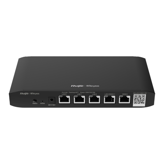
206.5 mm x 28 mm x 108.5 mm (8.13 in. x 1.1 in. x 4.27 in.) (W x H x D) Weight 0.55kg Warning Operation of this equipment in a residential environment could cause radio interference. Caution Use the power adapter provided by Ruijie. 1.1.2 Appearance Figure 1-1 Figure 1-1 Appearance of RG-EG105G V2... - Page 10 Hardware Installation and Reference Guide Product Overview Figure 1-2 Figure 1-2 Front Panel of RG-EG105G V2 Mark Item Description Fast blinking green: The router is starting up. Solid green: The router is functioning properly. System status LED Slow blinking green: 1. The router is restoring factory default settings.
-
Page 11: Power Supply
Status Blinking green (0.5Hz): The device is not connected to Ruijie Cloud. Solid green: The device has started up, and is connected to Ruijie Cloud. Blinking green (10Hz): The device is restoring the factory settings or starting up. Solid green: The port is up. -
Page 12: Rg-Eg105G-P V2
Hardware Installation and Reference Guide Product Overview RG-EG105G-P V2 1.2.1 Specifications Table 1-2 Technical Specifications of an RG-EG105G-P V2 Router Model RG-EG105G-P V2 Dual-core CPU with the clock speed of 880MHz Flash Memory 16MB SDRAM DDRIII 128MB AC input: Rated voltage range: 100V to 240V Power Module Maximum voltage range: 90V to 264V Frequency: 50/60 Hz... -
Page 13: Appearance
Hardware Installation and Reference Guide Product Overview Warning Operation of this equipment in a residential environment could cause radio interference. Caution Use the power adapter provided by Ruijie. 1.2.2 Appearance Figure 1-4 Figure 1-4 Appearance of RG-EG105G-P V2 Figure 1-5... -
Page 14: Power Supply
Hardware Installation and Reference Guide Product Overview Mark Item Description Connect the DC power adapter to the DC input plug on the Power supply faceplate of the router to power on the router. 10/100/1000BASE-T Ethernet RJ45 with auto negotiation. LAN ports Connect the LAN port to the PC, the switch or the access point with an Ethernet cable. -
Page 15: Heat Dissipation
1.2.6 LED Indicator LED Indicator Description Blinking green (0.5Hz): The device is not connected to Ruijie Cloud or PoE is overcurrent. Status Solid green: The device has started up, and is connected to Ruijie Cloud. Blinking green (10Hz): The device is restoring the factory settings or starting up. -
Page 16: Preparing For Installation
Hardware Installation and Reference Guide Preparing for Installation Preparing for Installation Safety Precautions Note ● To avoid personal injury and equipment damage, please carefully read the safety suggestions before you install the RG-EG V2 series router. ● The following safety precautions may not cover all possible dangers. 2.1.1 Installation ... -
Page 17: Static Discharge Damage Prevention
Hardware Installation and Reference Guide Preparing for Installation ● If a power supply system is equipped with a leakage protector (also referred to as "leakage current switch" or "leakage current breaker"), the rated leakage action current of each leakage protector is greater than twice of the theoretical maximum leakage current of all the power supplies in the system. -
Page 18: Ventilation
Hardware Installation and Reference Guide Preparing for Installation Make sure the cabinet is properly grounded. 2.2.2 Ventilation For the router, a sufficient space (at least 10 cm distances from both sides and the back plane of the cabinet) should be reserved at the ventilation openings to ensure the normal ventilation. After various cables have been connected, they should be arranged into bundles or placed on the cabling rack to avoid blocking the air inlets. -
Page 19: Cleanness
Hardware Installation and Reference Guide Preparing for Installation 2.2.4 Cleanness Dust poses a severe threat to the running of the equipment. The indoor dust falling on the equipment may be adhered by the static electricity, causing bad contact of the metallic joint. Such electrostatic adherence may occur more easily when the relative humidity is low, not only affecting the useful life of the equipment, but also causing communication faults. -
Page 20: Emi
Hardware Installation and Reference Guide Preparing for Installation Lightning Grounding The lightning protection system of a facility is an independent system that consists of the lightning rod, download conductor and the connector to the grounding system, which usually shares the power reference ground and yellow/green safety cable ground. -
Page 21: Installation Tool Requirements
Hardware Installation and Reference Guide Preparing for Installation Plastic wall anchor 4*20 wall anchor for self-tapping screw 2 Installation Tool Requirements Table 2-3 Table 2-4 List of Installation Tools Phillips screwdriver, related copper and fiber cables, bolts, diagonal pliers, Common Tools cable ties Special Tools Wire stripper, crimping pliers, RJ-45 crimping pliers, punch down tool... -
Page 22: Installing The Router
Hardware Installation and Reference Guide Installing the Router Installing the Router Installation Flowchart Please take the following steps: Figure 3-1 Installation Flowchart Confirmations before Installation Before installation, please confirm the following points:The installation site provides sufficient space for heat dissipation. ... -
Page 23: Mounting The Router
Hardware Installation and Reference Guide Installing the Router Mounting the Router 3.3.1 Mounting the Router to a Standard 19-inch Cabinet Please note that RG-EG105G V2 and RG-EG105G-P V2 can not be mounted to a cabinet. 3.3.2 Mounting the Router to a Workbench Please place the router on a clean workbench. -
Page 24: Verifying The Cables
Hardware Installation and Reference Guide Installing the Router 3.6.2 Verifying the Cables Verify that the fibers and twisted pairs match the ports. Verify that the cables have been bound properly. -
Page 25: System Debugging
Or connect the cable of AP to the LAN port of the router. After the AP is powered on, it will broadcast the SSID starting with @Ruijie-m. You can connect to the SSID for configuration. Figure 4-1 Schematic Diagram of the Configuration Environment Startup Check 4.2.1... -
Page 26: Configuring Router
Hardware Installation and Reference Guide System Debugging Configuring Router To use the router, more configuration should be made on the device. Please refer to the corresponding command reference and configuration guide. -
Page 27: Maintenance And Troubleshooting
Hardware Installation and Reference Guide Maintenance and Troubleshooting Maintenance and Troubleshooting General Troubleshooting Procedure Troubleshooting Common Faults Symptom Possible Causes Solution Press the Reset Button for more than password manually Forgetting the login password 5 seconds to restore the default configured but it is forgotten. -
Page 28: Appendix
Hardware Installation and Reference Guide Appendix Appendix Connectors and Connection Media 1000BASE-T/100BASE-TX/10BASE-T Ports The 1000BASE-T/100BASE-TX/10BASE-T is a port that supports adaptation of three rates, and automatic MDI/MDIX Crossover at these three rates. The 1000BASE-T complies with IEEE 802.3ab, and uses the cable of 100-ohm Category-5 or Supper Category- 5 UTP or STP, which can be up to 100 m. -
Page 29: Cabling Recommendations In Installation
Hardware Installation and Reference Guide Appendix Table 6-2 Figure A-3 Connections of the Twisted Pairs of the 100BASE-TX/10BASE-T Optical Fiber Connection For the optical fiber ports, select single-mode or multiple-mode optical fibers for connection according to the fiber module connected. The connection schematic diagram is shown in Figure A-4: Table 6-3 Figure A-4 Optical Fiber Connections Cabling Recommendations in Installation... -
Page 30: Precautions For Bundling Up Cables
Hardware Installation and Reference Guide Appendix 6.2.3 Precautions for Bundling up Cables Before bundling cables, correctly mark labels and stick the labels to cables where appropriate. Cables should be neatly and properly bundled, as shown in Figure D-1. Table 6-4 Figure B-1 Bundling Up Cables (1) ... - Page 31 Hardware Installation and Reference Guide Appendix the bend area. Otherwise, significant stress may be generated in cables, breaking cable cores. As shown in Figure D-3. Table 6-6 Figure B-3 Bundling Up Cables (3) Cables not to be assembled or remaining parts of cables should be folded and placed in a proper position of the cabinet or cabling slot.
- Page 32 Hardware Installation and Reference Guide Appendix Table 6-7 Figure B-4 Cable Fastening The hard power cable should be fastened by the terminal connection area to prevent stress. Do not use self-tapping screws to fasten terminals. Power cables of the same type and in the same cabling direction should be bundled up into cable bunches, with cables in cable bunches clean and straight.
Need help?
Do you have a question about the Reyee RG-EG V2 Series and is the answer not in the manual?
Questions and answers