Table of Contents
Advertisement
Ginlong Technologies Co., Ltd.
No. 57 Jintong Road, Binhai Industrial Park, Xiangshan, Ningbo,
Zhejiang, 315712, P.R.China.
Tel: +86 (0)574 6578 1806
Fax: +86 (0)574 6578 1606
Please adhere to the actual products in case of any discrepancies in this user manual.
If you encounter any problem on the inverter, please find out the inverter S/N
and contact us, we will try to respond to your question ASAP.
Solis Three Phase Inverter
Installation and Operation Manual
(125kW)
Ginlong Technologies Co., Ltd.
Ver 1.3
Advertisement
Table of Contents

Related Manuals for SOLIS Solis-125K-EHV-5G


Summary of Contents for SOLIS Solis-125K-EHV-5G
- Page 1 Solis Three Phase Inverter Installation and Operation Manual (125kW) Ver 1.3 Ginlong Technologies Co., Ltd. No. 57 Jintong Road, Binhai Industrial Park, Xiangshan, Ningbo, Zhejiang, 315712, P.R.China. Tel: +86 (0)574 6578 1806 Fax: +86 (0)574 6578 1606 Please adhere to the actual products in case of any discrepancies in this user manual.
-
Page 2: Table Of Contents
Contents Contents 1. Introduction 6.5 Settings ………………………………………………………………………………………………………………………………………… ……………………………………………………………………………………………………………………………… 1.1 Product Description 6.5.1 Set Time ……………………………………………………………………………………………………… …………………………………………………………………………………………………… 1.2 Unpacking and storage ……………………………………………………………………………………………… 6.5.2 Set Address …………………………………………………………………………………………………… 1.2.1 Storage 6.6 Advanced Info - Technicians Only ……………………………………………………………………………………………………………… …………………………………………………………………………… 2. Safety instructions 6.6.1 Alarm Message ………………………………………………………………………………………………………………………... -
Page 3: Introduction
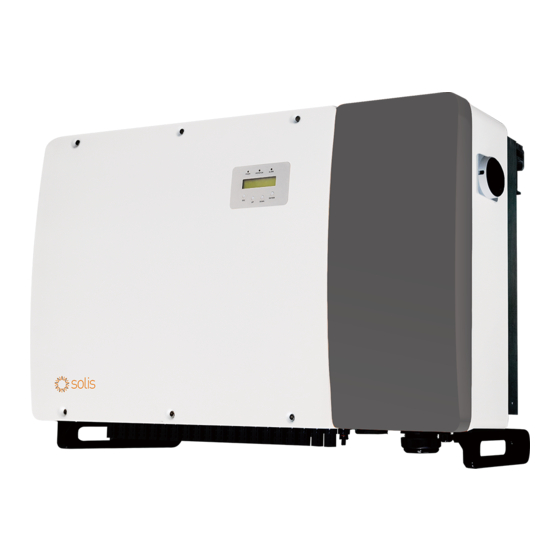
1.1 Product Description 1.2 Unpacking and storage Solis Three phase Inverters covert DC power from the photovoltaic(PV) array The inverter ships with all accessories in one carton. into alternating current(AC) power that can satisfy local loads as well as feed the power When unpacking, please verify all the parts listed below are included: distribution grid. -
Page 4: Storage
1. Introduction 2. Safety Instructions 1.2.1 Storage Improper use may result in electric shock hazards or burns. This product manual contains important instructions that are required to be followed during installation and maintenance. If the inverter is not installed immediately, storage instructions and environmental conditions are below: Please read these instructions carefully before use and keep them in an easily locatable place ●... -
Page 5: Notice For Use
Switch is turned on. To stop the inverter, the Grid Supply Main Switch (AC) must be turned off before the DC Switch is turned off. 500mm 2.4 Protection Circuitry and Controls To meet relevant codes and standards, the Solis three phase inverter line is 500mm equipped with protective circuitry and controls. Anti-Islanding Protection: Figure 3.1 Distances required between inverters... -
Page 6: Other Environmental Considerations
Consult the specifications section (section 9) for additional environmental conditions (protection rating, temperature, humidity, altitude, etc.). 3.1.2.2 Vertical wall installation This model of Solis inverter should be mounted vertically (90 degrees or Figure 3.3 Handles used to move the inverter shown circled in red backwards 15 degrees) . -
Page 7: Mounting The Inverter
3. Installation 3. Installation 3.3.1 Wall mounting Refer to figure 3.6 and figure 3.7 Inverter shall be mounted vertically. The steps to mount the inverter are listed below. 1. Refer to Figure 3.6, drill holes for mounting screws based on the hole diameter of bracket using a precision drill keeping the drill perpendicular to the wall. -
Page 8: Rack Mounting
3. Installation 3. Installation 3.3.2 Rack mounting The steps to mounted to the rack are listed below: 3. Install mounting plate 1. Select a location for the inverter 1) Remove the bracket and fasteners from the packaging. Mark the position for hole, drilling according to the hole positions of the bracket. -
Page 9: Electrical Connections
3. Installation 3. Installation 3.4 Electrical Connections 3) Align the mounting plate with the holes, Insert the combination bolt (M10X40)through the Inverter design uses PV style quick-connect terminal. The top cover needn't be opened mounting plate into the hole. Secure the bracket to the metal frame firmly with the supplied during DC electrical connection. -
Page 10: Grounding
3. Installation 3. Installation 3.4.1 Grounding 4) Insert the stripped wire into the OT terminal crimping area and use the hydraulic To effectively protect the inverter, two grounding methods must be performed. Connect the AC grounding cable (Please refer to section 3.4.3) clamp to crimp the terminal to the wire (see Figure 3.16). -
Page 11: Connect Pv Side Of Inverter
Before connecting the inverter, make sure the PV array open circuit voltage is within the limit of the inverter. Otherwise, the inverter could be damaged. Maximum 1500Vdc for Solis-125K-EHV-5G Crimping plier WARNING DO NOT connect the PV array positive or PV array negative cable to ground. -
Page 12: Connect Grid Side Of Inverter
Current for protection Inverter voltage(V) current (Amps) device (A) Solis-125K-EHV-5G Table 3.2 Rating of grid OCPD 3.4.3.1 Connecting the inverter to the utility grid Figure 3.24 Fuse holders All electrical installations must be carried out in accordance with the local standards and the National Electrical Code®... - Page 13 3. Installation 3. Installation 3.4.3.2 Wiring procedure CAUTION Copper terminal of cable RISK OF ELECTRIC SHOCK. Prior to starting the wiring procedure, ensure flat gasket that the three-pole circuit breaker is switched off and cannot be reconnected. spring washer NOTE Damage or destruction of the inverter's electronic components due to moisture and dust intrusion will occur if the enclosure opening is enlarged.
-
Page 14: Rs485 Communication
4. Comm. & Monitoring 4. Comm. & Monitoring 4.1 RS485 communication There are 5 communication terminals on Solis 125kW inverter. COM1 is a RS-485 communication supports two connections methods: RJ45 connectors/ Terminal 4-pin connector reserved for WiFi/Cellular datalogger. COM2 and COM3 are RS485 board.(Default Modbus RTU) -
Page 15: Ethernet Communication
Use the RJ45 connectors to perform the Ethernet communication which supports the The cross sectional area of the cable wire for terminal board connection should be 0.2-1.5mm. Solis Monitoring Platform and Modbus TCP protocol(Both By Default). The outer diameter of the cable may be 5mm-10mm. - Page 16 After the daisy chain connection is finished, please use the SN/QR code on the board to NOTE: Laptop IP Configuration register the system on Solis monitoring website or APP. Step 1: With a network cable to connect the computer and LAN Stick, right-click the computer icon in the lower right corner of the computer, enter the “network and sharing center”.
-
Page 17: Commissioning
3). Use the UP/DOWN keys to highlight the SELECT STANDARD option. Press enter to select. Solis inverters are used worldwide and feature preset standards for operating on any grid. Although the grid standard is set at the factory, it is essential the grid standard be verified for the country of installation before commissioning. -
Page 18: Preliminary Checks
Verify DC configuration by noting the number of panels in a string and the string voltage. Solis inverters are transformer-less and do not have an array connection to ground. Any measurement of a fixed voltage between ground and either the positive or negative string 5.4.3.1 VOC and Polarity... -
Page 19: Ac Configuration
3). If the meter is equipped, measure the frequency of each phase to ground. 4). Solis inverters are powered from the DC side. When the inverter detects DC 4). Ensure each measurement is within local grid standards and the inverter specifications power that is within start-up and operating ranges, the inverter will turn on. -
Page 20: Main Menu
DRM NO.:08 DRM NO.: Shows DRM Number. 6.4 Information I_DC01 : Shows input 01 current value. The Solis three Phase Inverter main menu provides access to operational I_DC01: +05.0A I_DC02 : Shows input 02 current value. I_DC02: +04.9A data and information. The information is displayed by selecting "Information" from the 10 sec I_DC20: +05.2A... -
Page 21: Lock Screen
This function is used to set the address when muti inverters are connected to three monitor. The address number can be assigned from “01”to “99”(see Figure 6.4). The default address number of Solis Three Phase Inverter is “01”. Alm000: OV-G-V T: 00-00 00:00 D:0000 YES=<ENT>... -
Page 22: Version
6. Normal operation 6. Normal operation 6.6.3 Version 6.6.6 Yearly Energy The screen shows the model version of the inverter. And the screen will show the The function is for checking the energy generation for selected year. software ver by pressing the UP and DOWN at the same time.(see Figure 6.7). YES=<ENT>... -
Page 23: Advanced Settings - Technicians Only
16.I/V Curve 6.7.2 Grid ON/OFF 6.7.1 Selecting Standard This function is used to start up or stop the power generation of Solis Three Phase This function is used to select the grid's reference standard (see Figure 6.16). Inverter (see Figure 6.18). -
Page 24: Reset Password
6. Normal operation 6. Normal operation 6.7.4 Reset Password 6.7.7 Special Settings This function is used to set the new password for menu “Advanced info.” and “Advanced information” (see Figure 6.19). This function is applicable by maintenance personnel only, wrong operation will prevent the inverter from reaching maximum power. -
Page 25: Hmi Update
6. Normal operation 6. Normal operation 6.7.10 HMI Update 6.7.13 Debug Parameter This section is applicable to maintenance personnel only. This section is applicable to maintenance personnel only. Debug Parameter as shown as below: Selecting “Updater” displays the sub-menu shown below: →... -
Page 26: Dsp Update
6. Normal operation 6. Normal operation 6.7.15 DSP Update 6.7.17 I/V Curve The function is used for update the DSP. This function is used to scan the I/V characteristic curves of each PV strings. Set I/V Curve This function is applicable by maintenance personnel only, wrong operation I/V Curve Scan will prevent the inverter from reaching maximum power. -
Page 27: Maintenance
7. Maintenance 7. Maintenance Solis Three Phase Inverter does not require any regular maintenance. However, NOTE: cleaning the dust on heat-sink will help the inverter to dissipate the heat and increase its life If you need to maintain the inverter at night, please turn off the AC switch first, time. -
Page 28: Fuse Maintenance
7. Maintenance 7. Maintenance 6. Disconnect the fan connector carefully and take out the fan. The fuse spec is 1500V/20A. When replacing the fuses, please select the fuses with the same specification. 7.4 Surge Protection Device Maintenance If surge protection device is damaged, it will affect the safety of the inverter. It is necessary to replace it with a new lightning protection module. -
Page 29: Troubleshooting
8. Troubleshooting 8. Troubleshooting The inverter is designed in accordance with the most important international grid-tied Alarm Message Failure description Solution standards and safety and electromagnetic compatibility requirements. Before delivering to INI-FAULT Initialization system fault the customer, the inverter has been subjected to several tests to ensure its optimal operation and reliability. -
Page 30: Specifications
Self consumption (night) Operating ambient temperature range -25℃...+60℃ 1. Serial number of Solis Three Phase Inverter; Relative humidity 0~100% 2. The distributor/dealer of Solis Three Phase Inverter (if available); Ingress protection NEMA4X/IP65 3. Installation date. ≤55dB(A) Noise emission 4. The description of problem (i.e. the alarm message displayed on the LCD and the status... -
Page 31: Appendices
10. Appendices P(%) 100% T(℃) Figure 10.1 Comments: A thermal sensor inside the inverter is calibrated to determine ambient temperature. All inverters will begin a sloped derate at 50C ending at 50% output power at 60C. Temperatures above 60C and below -25C will derate to 0% output power. P(%) 100% Input Voltage(V)
Need help?
Do you have a question about the Solis-125K-EHV-5G and is the answer not in the manual?
Questions and answers