Page 1
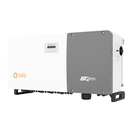
Solis Three Phase Inverter Installation and Operation Manual Solis-(75-110)K-5G-PRO Ver 1.2 Ginlong Technologies Co., Ltd. No. 57 Jintong Road, Binhai Industrial Park, Xiangshan, Ningbo, Zhejiang, 315712, P.R.China. Tel: +86 (0)574 6578 1806 Fax: +86 (0)574 6578 1606 Please adhere to the actual products in case of any discrepancies in this user manual.
1.1 Product Description 1.2 Unpacking and storage Solis Three phase Inverters covert DC power from the photovoltaic(PV) array The inverter ships with all accessories in one carton. into alternating current(AC) power that can satisfy local loads as well as feed the power When unpacking, please verify all the parts listed below are included: distribution grid.
1. Introduction 2. Safety Instructions 1.2.1 Storage Improper use may result in electric shock hazards or burns. This product manual contains important instructions that are required to be followed during installation and maintenance. If the inverter is not installed immediately, storage instructions and environmental conditions are below: Please read these instructions carefully before use and keep them in an easily locatable place ●...
2. Safety Instructions 3. Installation 3.1 Environmental Considerations 3.1.1 Select a location for the inverter CAUTION When selecting a location for the inverter, consider the following: Risk of electric shock from energy stored in the inverter's capacitors. Do not remove cover until five (5) minutes after disconnecting all sources WARNING: Risk of fire of supply have passed, and this can only be done by a service technician.
3. Installation 3. Installation 3.1.1.1 Examples of correct and incorrect installations 3.1.2 Installation environment requirements ● Avoid Direct Sunlight Installation of the inverter in a location exposed to direct sunlight should be avoided. Direct exposure to sunlight could cause: Inverter temperature rises. Output power limitation (Leads to a reduction of system generation).
3. Installation 3. Installation 1129 unit:mm Figure 3.6 Inverter wall mounting for (100-110)K Figure 3.4 Inverter handles 1199 WARNING Due to the weight of the inverter, contusions or bone fractures could occur when incorrectly lifting and mounting the inverter. When mounting the inverter, take the weight of the inverter into consideration.
3. Installation 3. Installation 3.3.1 Wall mounting 3.3.2 Rack mounting Refer to figure 3.8 and figure 3.9 Inverter shall be mounted vertically. The steps to mounted to the rack are listed below: The steps to mount the inverter are listed below. 1.
3. Installation 3. Installation 3.4 Electrical Connections 3. Install mounting plate Inverter design uses PV style quick-connect terminal. The top cover needn't be opened during DC electrical connection. The labels located the bottom of the inverter are described 1) Remove the bracket and fasteners from the packaging. Mark the position for hole, below in table 3.1.
3. Installation 3. Installation 3.4.1 Grounding 4) Insert the stripped wire into the OT terminal crimping area and use the hydraulic To effectively protect the inverter, two grounding methods must be performed. Connect the AC grounding cable (Please refer to section 3.4.3) clamp to crimp the terminal to the wire (see Figure 3.16).
3. Installation 3. Installation 3.4.2 Connect PV side of inverter 5. Measure PV voltage of DC input with multimeter, verify DC input cable polarity (see figure 3.22), and ensure each string voltage is in range of inverter operation. WARNING Before connecting the inverter, make sure the PV array open circuit Connect DC connector with inverter until hearing a slight clicking sound indicating voltage is within the limit of the inverter.
Page 12
3. Installation 3. Installation 3.4.2.3 String Input Instructions Requirements for the PV modules per MPPT input: ● All PV modules must be of the same type and power rating. NOTE ● Please ensure the PV strings are evenly connected to the inverter and try to utilize all the To achieve the best power generation effect, add components according MPPT trackers.
Page 13
3. Installation 3. Installation Recommended access scheme for 210mm component of (75-80)K inverter Recommended access scheme for 182mm component of (100-110)K inverter The (75-80)K inverter has three sets of power modules inside, as shown in the figure below. The (100-110)K inverter has four sets of power modules inside, as shown in the figure below. In order to achieve the best power generation, we strongly recommend that the three power In order to achieve the best power generation, we strongly recommend that the four power modules are evenly connected to the solar panels.
Power Module 4 (PV 1-4) (PV 5-8) (PV 9-12) (PV 13-16) Rated Rated output Current for protection Inverter voltage(V) current (Amps) device (A) 220/380,230/400 Solis-75K-5G-PRO ≤11.3≤11.3≤11.3kW 220/380,230/400 Solis-80K-5G-PRO 121.6/115.5 Solis-100K-5G-PRO 220/380,230/400 152.0/144.3 Case 2 220/380,230/400 Solis-110K-5G-PRO 167.1/158.8 Power Module 1...
Page 15
3. Installation 3. Installation 3.4.3.2 Wiring procedure 2. Strip the insulation of the wire past the cable crimping area of the OT terminal, CAUTION then use a hydraulic crimp tool to crimp the terminal. The crimped portion of the terminal RISK OF ELECTRIC SHOCK.
Monitoring system for multiple inverters Multiple inverters can be monitored through RS-485 daisy chain configuration. NOTE Solis three phase inverters integrate neutral connection point. However, with or without neutral connected won't affect the normal operation of inverter Inverter PV Strings itself.
4. Comm. & Monitoring 4. Comm. & Monitoring Use the network wire stripper to strip the insulation layer off the communication cable. Connection of Terminal board. Using the standard wire sequence referenced in TIA/EIA 568B, separate the wires in the cable. a.
PLC is available for multiple inverter monitoring. 5.1.1 Verifying grid standard for country of installation Solis inverters are used worldwide and feature preset standards for operating on any grid. Although the grid standard is set at the factory, it is essential the grid standard be verified for the country of installation before commissioning.
(see “Specifications” in section 10) may damage the inverter. Although Solis inverters feature reverse polarity protection, 1). Please refer to section 6.7 “Advanced Settings” for procedures to create a custom grid prolonged connection in reverse polarity may damage these protection circuits and/or the inverter.
5.4.4.1 Measure Vac and frequency 4). Solis inverters are powered from the DC side. When the inverter detects DC Measure VAC and verify voltage is within local grid standards. power that is within start-up and operating ranges, the inverter will turn on. After turn- 1).
DRM NO.:08 DRM NO.: Shows DRM Number. 7.2 Information I_DC01 : Shows input 01 current value. The Solis three Phase Inverter main menu provides access to operational I_DC01: +05.0A I_DC02 : Shows input 02 current value. I_DC02: +04.9A data and information. The information is displayed by selecting "Information" from the 10 sec I_DC20: +05.2A...
This function is used to set the address when muti inverters are connected to three monitor. The address number can be assigned from “01”to “99”(see Figure 7.4). The default address Alm000: OV-G-V number of Solis Three Phase Inverter is “01”. T: 00-00 00:00 D:0000 Figure 7.6 Alarm Message YES=<ENT>...
7. Normal operation 7. Normal operation 7.4.3 Version 7.4.6 Yearly Energy The screen shows the model version of the inverter. And the screen will show the The function is for checking the energy generation for selected year. software ver by pressing the UP and DOWN at the same time.(see Figure 7.7). YES=<ENT>...
17. I/V Curve 7.5.2 Grid ON/OFF 7.5.1 Selecting Standard This function is used to start up or stop the power generation of Solis Three Phase Inverter. This function is used to select the grid's reference standard (see Figure 7.16). Grid ON Grid OFF YES=<ENT>...
7. Normal operation 7. Normal operation 7.5.4 Reset Password 7.5.7 Special Settings This function is used to set the new password for menu “Advanced info.” and “Advanced information” (see Figure 7.19). This function is applicable by maintenance personnel only, wrong operation will prevent the inverter from reaching maximum power.
7. Normal operation 7. Normal operation 7.5.9 Restore Settings 7.5.12 Restart HMI There are 5 items in initial setting submenu. The function is used for restart the HMI. Restore setting could set all item in 7.5.7 special setting to default. The screen shows as below: This function is applicable by maintenance personnel only, wrong operation will prevent the inverter from reaching maximum power.
7. Normal operation 7. Normal operation 7.5.15 DSP Update 7.5.17.1 Set I/V Curve The function is used for update the DSP. This setting can set the scanning voltage start point and the voltage interval. 850V This function is applicable by maintenance personnel only, wrong operation 010V will prevent the inverter from reaching maximum power.
8. Maintenance 7.6 AFCI function Solis inverters have the built-in AFCI function which can detect the arc fault on the DC circuit Solis Three Phase Inverter does not require any regular maintenance. However, and shut down the inverter to prevent a fire disaster.
8. Maintenance 9. Troubleshooting 8.2 Fan Maintenance If the fan does not work properly, the inverter will not be cooled effectively. The inverter is designed in accordance with the most important international grid-tied and it may affect the effective operation of the inverter . standards and safety and electromagnetic compatibility requirements.
2.Identify which string cause the fault and 01/02 check the isolation of the string. 1. Serial number of Solis Three Phase Inverter; 2. The distributor/dealer of Solis Three Phase Inverter (if available); ILeak-PRO 1.Check AC and DC connection Leakage current protection 01/02/03/04 2.Check inverter inside cable connection.
10. Specifications 10. Specifications Model Solis-75K-5G-PRO Model Solis-80K-5G-PRO Max. DC input voltage (Volts) 1100 Max. DC input voltage (Volts) 1100 Rated DC voltage (Volts) Rated DC voltage (Volts) Start-up voltage (Volts) Start-up voltage (Volts) MPPT voltage range (Volts) MPPT voltage range (Volts) 160...1000...
Page 32
10. Specifications 10. Specifications Model Solis-100K-5G-PRO Model Solis-110K-5G-PRO Max. DC input voltage (Volts) 1100 Max. DC input voltage (Volts) 1100 Rated DC voltage (Volts) Rated DC voltage (Volts) Start-up voltage (Volts) Start-up voltage (Volts) MPPT voltage range (Volts) MPPT voltage range (Volts) 160...1000...
Need help?
Do you have a question about the 75K-5G-PRO and is the answer not in the manual?
Questions and answers