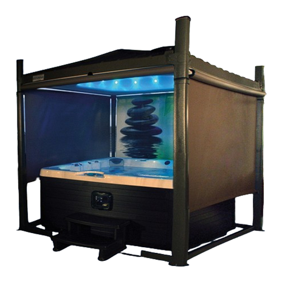
COVANA OASIS Owner's Manual
Cover
Hide thumbs
Also See for OASIS:
- Installation manual (62 pages) ,
- User manual (32 pages) ,
- Replacement procedure (4 pages)
Table of Contents
Advertisement
Advertisement
Table of Contents

Related Manuals for COVANA OASIS


Summary of Contents for COVANA OASIS
- Page 3 OASIS COVER page - COVANA SPA COVER MANUFACTURER OWNER'S MANUAL MANUAL NO. 241146 REVISION 0 2021-01-01 241146 OWNER'S MANUAL REVISION 0...
- Page 4 OASIS COVER OASIS COVER MANUAL NO. 241146 First edition 2021-01-01 REVISION DESCRIPTION DATE OWNER'S MANUAL NEW RELEASE 2021-01-01 241146 OWNER'S MANUAL REVISION 0...
- Page 5 OASIS COVER page- INTRODUCTION CONGRATULATIONS FOR THE PURCHASE OF YOUR NEW COVANA COVER IMPORTANT INFORMATION SAFETY DRUGS AND ALCOHOL SAFETY INSTRUCTIONS MODIFICATIONS TO THE COVER POSITION OF THE KEYSWITCH LABELING RISK OF ELECTROCUTION INFORMATION ON THE ELECTRICAL CABLES KEY SWITCH DIAGRAM...
- Page 6 WIRING DIAGRAM (EUROPE) (LIGHTS)– 50 HZ, 230 VAC OPERATOR MAINTENANCE WINTERIZING WASHING THE COVER POST GREASING CHAIN LUBRICATION PERIODIC MAINTENANCE TABLE TECHNICAL SPECIFICATIONS COVANA COVER FRONT VIEW FRAME DIMENSIONS AND FOOT PRINT CONCRETE SLAB LAYOUT OPTION ELECTRICAL SPECIFICATIONS TROUBLESHOOTING COVANA LIMITED WARRANTY WARRANTY COVERAGE LIMITATIONS...
- Page 7 OASIS COVER page- INTRODUCTION As part of its ongoing commitment to improve the quality, reliability, durability and safety of its products, Covana is proud to present this edition of the cover Owner's Manual. The various sections that make up this manual will provide you with the most recent information allowing you to understand the operation of the cover, its installation and its maintenance in order to obtain complete satisfaction and to ensure maximum safety and comfort for users.
-
Page 8: Drugs And Alcohol
Covana. SAFETY The cover was designed, tested and certified to be installed over a spa and under important installation instructions issued by Covana. Any other type of 241146 OWNER'S MANUAL REVISION 0... - Page 9 Do not allow children to have access to the cover operation without supervision. Have any repairs, adjustments or mechanical work performed by a certified Covana dealer as Never operate the cover until all people and soon as possible when you notice any objects are removed out of the spa.
- Page 10 OASIS COVER DON'T CAUTION Do not operate the unit before all mechanical All four jacks of the cover must be properly and electrical connections are completely anchored to the foundation using the anchoring installed. holes of the jack base plate. The optional non-...
- Page 11 Covana. mm / 13.30mm ). (NEC art. 680.) Replace electrical components with original components provided or approved by Covana. MODIFICATIONS TO THE COVER Ask your dealer for replacement parts. To reduce the risk of electrical shock, replace a damaged electrical cord immediately.
- Page 12 OASIS COVER POSITION OF THE KEYSWITCH WARNING The keyswitch must be permanently installed and located 5 ft. (1.5 m) away from the spa and 5 ft. (1.5 m) above the deck or ground level. Make sure the user has a clear view of the cover when operating it.
-
Page 13: Risk Of Electrocution
OASIS COVER page- INFORMATION ON THE ELECTRICAL LABELING CABLES This section shows the location of all safety labels. These labels inform you about the risk of They are positioned on various components for your electrocution with presence water safety. accumulations. - Page 14 OASIS COVER KEY SWITCH DIAGRAM TECHNICAL SPECIFICATION LABEL This label shows you how to turn the key into the key These labels show you the important technical switch to lift up or lower the cover. specifications. They are located on the operator cover.
- Page 15 The cover is labeled on four exterior and interior wall faces. If the labels are damaged or no longer meet legibility requirements, please obtain replacement labels by contacting Covana or your local Covana dealer. FIGURE 10: LOCATION OF THE AVOID DROWNING...
- Page 16 OASIS COVER GLOSSARY PART IMAGE FUNCTION This all-weather seal protects sleeves from damage due Sleeve all-weather seal to weather. The contour seal makes sure there is uniform contact Contour seal between the cover panels and the spa. Contour seal installation clips are used during the...
- Page 17 OASIS COVER page- PART IMAGE FUNCTION The foot bracket provides a solid footing of the cover and Foot bracket is attached to the bottom of the jack. Spa entrance U-frame This link is installed under the entrance steps of the spa.
- Page 18 OASIS COVER PART IMAGE FUNCTION Jacks are a very important component of the cover. They Jack allow the cover to lift up and down. The operator powers and controls the lifting mechanism Operator of the cover. The sleeves are aluminum extrusions to hide and protect Sleeve the jacks.
- Page 19 OASIS COVER page- PART IMAGE FUNCTION The wire guard is an assembly that will house a wire that comes from the cover to light up the LED light kit. It Wire guard (optional) protects the wire from becoming overly taut and will release extra wire if necessary.
-
Page 20: Installation Procedure
Make sure the base of the cover is not in a flood zone. Any damage caused by flooding or water The cover should be installed by a certified Covana accumulation will not be covered by the warranty. installer. Having the cover installed by someone who is not certified will void the warranty. - Page 21 CAUTION Damage caused inadequate foundation construction is not covered by the Covana warranty. It is the responsibility of the owner to provide a proper foundation. Failure to follow these guidelines might cause permanent damage or improper functioning of the cover. Such damage might not be covered by the warranty.
- Page 22 It also shows how to unpack components. NOTE If you find any damage, refer to the Covana Damaged claim form attached to the crate, take pictures and simply refuse the delivery from the carrier.
-
Page 23: Unpacking Procedure
OASIS COVER page- FIGURE 17: SECURE THE PERIMETER FIGURE 16: DO NOT TIE FROM THE TOP OF THE CRATE UNPACKING PROCEDURE Always make a visual inspection of the condition of the crate before attempting any action with the 1. Before unpacking the unit, make sure there is forklift. - Page 24 OASIS COVER CAUTION Be careful not to damage the cover components and other parts in the crate. Flatten all protruding nails. FIGURE 20: REMOVE COMPONENTS FROM CRATE DESCRIPTION SLEEVE BOXES HARDWARE BOX CONTOUR SEAL FIGURE 19: REMOVE CARDBOARD AND STRIPS FOAM SPACERS 4.
- Page 25 OASIS COVER page- FIGURE 23: LOOSEN TOP SCREW ON JACKS FIGURE 21: MOTOR FRAME ASSEMBLY REMOVAL WARNING 8. Reinstall the screws (2) on the operator cover. Do not remove the alignment bracket on the top of the jack (red part).
- Page 26 OASIS COVER FIGURE 25: FOOTING PIECE OF WOOD REMOVAL FIGURE 24: MOTOR FRAME ASSEMBLY REMOVAL CAUTION CAUTION Flatten any protruding nails. Do not twist the motor frame assembly, since this 13. Remove the two long U-frames, the two short...
- Page 27 OASIS COVER page- pivot point see Figure CAUTION Dropping the crate could damage the cover. FIGURE 28: WOOD FURRING STRIP REMOVAL 18. This step is divided in 3 substeps: Substep 1: Use a Phillips screwdriver to remove the two M6 x 20 mm screws.
- Page 28 OASIS COVER CAUTION Do not remove the side panels completely, doing so may damage the cover FIGURE 31: PIVOT GENTLY THE SIDE PANELS FIGURE 29: COVER BRACKET REMOVAL 21. Pull the bottom section out, making sure that 19. Use the Robertson screwdriver to remove the it does not interfere with the cover.
- Page 29 OASIS COVER page- HARDWARE IDENTIFICATION TABLE ID QTY DESCRIPTION 5/16″-18 x 2″ HEX BOLT USED TO ASSEMBLE THE LOWER FRAME 1/4″-20 x 2 1/4″ HEX BOLT USED TO ASSEMBLE THE FEET OF THE POSTS 1/4″-20 x 3/4″ CARRIAGE BOLT USED TO ASSEMBLE THE FRONT FRAME CUT-OUT M6 x 20 mm SCREW USED TO FASTEN THE COVER AND SLEEVE #8 x 1/2″...
-
Page 30: Assembly Preparation
OASIS COVER ASSEMBLY PREPARATION WARNING Before assembling, keep in mind to not over tighten the screws. Power tools must not be used. The screws may break if the torque is too much. 1. Install foam spacers on the top of the spa near each corner. - Page 31 OASIS COVER page- whereas the long- side model will need the motor frame on the long side of the cover. FIGURE 36: FOOT BRACKET INSTALLATION 3. Slide the alignment vertical legs of the foot in FIGURE 35: OPERATOR AND JACKS INSTALLATION...
- Page 32 OASIS COVER FIGURE 38: SCREW INSTALLATION FIGURE 39: DRIVE SHAFT INSTALLATION 6. Repeat previous steps with the non- motor 9. Hold the left- hand non- motor- side jack right-hand side foot. assembly upright and in line with the left drive shaft.
- Page 33 OASIS COVER page- NOTE Do not fully tighten screws. The drive shaft may fall off during operation, and reassembling can be done faster when the bolts have not been fully tightened see Figure FIGURE 42: SPA ENTRANCE U-FRAME LINK AND METAL...
- Page 34 OASIS COVER FIGURE 43: SHORT U-SHAPE INSTALLATION 15. Check whether the drive shafts fell off during installation. If so, review the previous steps. If not, tighten all U-frame screws. FIGURE 44: JACK LOCK SCREW DANGER DESCRIPTION Failure to verify the proper installation of the drive...
- Page 35 OASIS COVER page- CAUTION Make sure that the nylon washer is located on the outside of the outer sleeve. FIGURE 45: CLIP-ON BARREL NUT INSTALLATION DESCRIPTION CLIP-ON BARREL NUT FIGURE 47: MOUNTING SCREW ON THE SLEEVE M6 SCREW 21. Make sure the sleeve seal on each post is slid...
- Page 36 OASIS COVER CAUTION Make sure that the wider part of the bushing is facing up when you screw in the 3/8″-24 x1″ Allen bolt see Figure Ensure the hole in each top plate is aligned with the jack assembly’s threads before installing the...
- Page 37 OASIS COVER page- FIGURE 52: CABLE TIE REMOVAL DESCRIPTION CTS-70 (CONTINUOUS TENSION SYSTEM) FIGURE 51: OUTER SHELL LIFTING WIRE GARD DESCRIPTION OUTER SHELL STEEL FRAME METAL INSERT 4. While holding the outer shell open, cut and remove the two cable ties that hold the wire...
- Page 38 OASIS COVER 8. Use the supplied alcohol swab and rub it on the surface of the outer sleeve positioned on the opposite corner of the light button to clean the surface see Figure 55 Figure 56. Wait two minutes for the alcohol to dry.
- Page 39 OASIS COVER page- FIGURE 58: WIRE GUARD BOTTOM POSITION FIGURE 57: RED PLASTIC FILM SHORT PORTION 13. Fit the wire guard on the corner of the post. REMOVAL Make sure no wires are pinched and that the 12. Align and position the bottom of the wire...
- Page 40 OASIS COVER FIGURE 60: RED FILM REMOVAL 15. Now connect the bottom harness to the wire guard connector. The bottom harness is attached to the key switch cable. Cut the FIGURE 62: MAGNETIC PLATE cable tie that holds the bottom harness.
- Page 41 OASIS COVER page- 19. Slide the outer shell back on the inner shell. screw on position A and for the remaining The AC light kit has been successfully screws, keep following the pattern shown in installed. Figure CAUTION WARNING Make sure the sleeve is correctly pressed against...
- Page 42 OASIS COVER FIGURE 66: INSTALLATION PATTERN FOR CORNER FIGURE 68: SLEEVE INSTALLATION CHECKING BRACKET SCREWS ATTACHED TO THE SLEEVE 8. Install the rubber caps on all posts. These caps protect the post assembly tops from WARNING weathering see Figure Make sure there is no gap between the sleeve and the bracket.
- Page 43 NOTE This setup is only available for spa base sizes larger than 82” wide for standard Covana units and 87” wide for long side Covana units. FIGURE 71: PLATE AND U-FRAME 1. After the unit has been installed, but before installing the seal, proceed with the non- 2.
-
Page 44: Seal Installation
Covana is not responsible for any misuse of the tool and any damage done to the spa or the cover while using the roller. CAUTION It is recommended to install the seal when the ambient temperature is above 50°F (10°C) - Page 45 OASIS COVER page- FIGURE 75: DOUBLE CLIP INSTALLATION 6. Start installing the seal joint with the adhesive FIGURE 74: MASKING TAPE AND CLIPS layer facing up towards the cover see Figure Figure WARNING CAUTION The use of masking tape is recommended since it will protect the spa acrylic from the clip glue.
-
Page 46: Electrical Connections
OASIS COVER or your fingers to help release the seal from WARNING the clips. At this point, if there is no water in the spa and the 12. Once satisfied that the seal is released, lift up ambient air temperature is below 50°F (10°C), a the cover 36”... - Page 47 Covana. Replace electrical components with original components provided or approved by Covana. Ask your dealer for replacement parts. To reduce the risk of electrical shock, replace a damaged electrical cord immediately. Failure to do so may result in death or serious personal injury due to electrocution.
- Page 48 OASIS COVER GROUNDING AND POWER SUPPLY CONNECTIONS 1. Remove the screws (4) on the bottom side of the operator cover and remove the cover see Figure 2. For the complete wiring diagrams refer to section Electrical diagrams (North American models and European models).
-
Page 49: Limit Switch Adjustment
OASIS COVER page- LIMIT SWITCH ADJUSTMENT Figure 80. Be careful not to rotate the cam wheels. WARNING Disconnect or turn off the power supply before starting any work on the cover. All electrical work should be performed by a qualified electrician. - Page 50 OASIS COVER FIGURE 81: CAM WHEELS 5. Once the up limit is set to the desired position, reinstall the cam plate to its original location and make sure that it is properly inserted in the slot of each cam. Never operate the system without the cam plate and retaining screw installed.
- Page 51 OASIS COVER page- INSTALLATION CHECKLIST (CUSTOMER COPY) To ensure proper installation you must carefully read this checklist and confirm that you have completed all steps of the installation. The customer must receive a completed copy of this checklist. (Please check each circle when the point is completed) The base preparation steps are done correctly (Location and foundation preparation sections).
- Page 53 OASIS COVER page - INSTALLATION CHECKLIST (INSTALLER COPY) To ensure proper installation you must carefully read this checklist and confirm that you have completed all steps of the installation. The customer must receive a completed copy of this checklist. (Please check each circle when the point is completed) The base preparation steps are done correctly (Location and foundation preparation sections).
- Page 55 OASIS COVER page- LED LIGHT KIT (OPTIONAL) OPERATE THE To operate the Covana light system, press on the COVER light switch located under the cover on one of its corners. The Covana lights can operate in two different modes. You can select the mode by...
- Page 56 OASIS COVER 5. Turn the extension shaft clockwise to lower the cover and counterclockwise to raise the cover. WARNING Do not exceed the limits of the mechanism. Failure to respect this guideline may cause mechanical failure. 6. Reinstall the operator cover with the four screws.
-
Page 57: Electrical Diagrams
6. Operate the cover by cycling it up and down. If the plate still comes off due to excessive tension, consult the Troubleshooting section or call your local Covana dealer. ELECTRICAL DIAGRAMS FIGURE 87: WIRE LOOP Next pages of this section show electrical diagrams 3. - Page 58 OASIS COVER WIRING DIAGRAM (NORTH AMERICA) – 60 HZ, 120 VAC OPERATOR 241146 OWNER'S MANUAL REVISION 0...
- Page 59 OASIS COVER page- 241146 OWNER'S MANUAL REVISION 0...
- Page 60 OASIS COVER WIRING DIAGRAM (NORTH AMERICA) (LIGHTS)– 60 HZ, 120 VAC OPERATOR 241146 OWNER'S MANUAL REVISION 0...
- Page 61 OASIS COVER page- 241146 OWNER'S MANUAL REVISION 0...
- Page 62 OASIS COVER WIRING DIAGRAM (EUROPE) – 50 HZ, 230 VAC OPERATOR 241146 OWNER'S MANUAL REVISION 0...
- Page 63 OASIS COVER page- 241146 OWNER'S MANUAL REVISION 0...
- Page 64 OASIS COVER WIRING DIAGRAM (EUROPE) (LIGHTS)– 50 HZ, 230 VAC OPERATOR 241146 OWNER'S MANUAL REVISION 0...
- Page 65 OASIS COVER page- 241146 OWNER'S MANUAL REVISION 0...
-
Page 66: Maintenance
Using any type of fabric or plastic canvas to cover the Covana cover during hot weather may damage the components. Only use such protection for the winterization procedure and during the cold season. - Page 67 OASIS COVER page- WARNING Never use a pressure washer or high pressure to clean the cover. The high pressure may damage the fiberglass roof. Never use harsh detergents that may cause a chemical reaction and permanently damage the surface. Do not use abrasive cleaners.
- Page 68 7. Raise the jacks until they reach the maximum 9. Inspect the chains for signs of deterioration. If height see Figure this is the case, please call your local Covana dealer immediately see Figure FIGURE 94: JACK CHAINS FIGURE 92: JACKS RAISING 10.
-
Page 69: Chain Lubrication
OASIS COVER page- CHAIN LUBRICATION This procedure shows how to lubricate the transmission power chain attached to the operator. The “Mobil Epic EP MOLY Grease” is recommended for cold and hot climates. Ideally, a sprayable grease or an equivalent low temperature synthetic grease. -
Page 70: Periodic Maintenance Table
Grease the jack assemblies. * Wash the cover with a mild detergent (i.e., dishwashing detergent) and water. Rinse well using only water. *Contact your local Covana dealer Please call your Covana dealer for any mechanical, electrical or aesthetic maintenance. 241146 OWNER'S MANUAL REVISION 0... -
Page 71: Technical Specifications
OASIS COVER page- TECHNICAL SPECIFICATIONS COVANA COVER FRONT VIEW 241146 OWNER'S MANUAL REVISION 0... -
Page 72: Frame Dimensions And Foot Print
OASIS COVER FRAME DIMENSIONS AND FOOT PRINT INCH (mm) STANDARD 100.5 105.75 92.75 130.75 MODEL (2692) (2553) (889) (2297) (2685) (2356) (2489) 3321) (1321) LONG SIDE 105.75 100.5 92.75 130.75 MODEL (2845) (2685) (991) (2870) (2553) (2489) (2356) (3321) - Page 73 OASIS COVER page- CONCRETE SLAB LAYOUT OPTION INCH (mm) STANDARD 100.5 105.75 92.75 130.75 MODEL (2692) (2553) (889) (2297) (2685) (2356) (2489) 3321) (1321) LONG SIDE 105.75 100.5 92.75 130.75 MODEL (2845) (2685) (991) (2870) (2553) (2489) (2356) (3321) (1448)
- Page 74 10 A single-pole GFCI (not included) Current draw Max 6 A WARNING Covana does not allow any modifications of the electrical system. Covana reserves the right to void the warranty if any modifications is done without its approval. OPERATION LIMITATIONS WARNING The cover should never be used if the following conditions are reached.
-
Page 75: Troubleshooting
Verify the relative position of the four posts heavy. (See Foundation Preparation section). The power source is disconnected. Call your Local authorized Covana dealer. Lower the cover completely and fasten the post The post screws (attached to the back in at the correct height. - Page 76 If all previous attempts failed, contact your local authorized Covana dealer. Check level on 2 faces of the sleeve. The chain is broken. Call your local certified Covana dealer for A spring pin is broken. The cover raises technical support.
- Page 77 OASIS COVER page- PROBLEM PROBABLE CAUSES SOLUTIONS Cover seal turned Clean the affected areas with bleach and a The seal has accumulated mold. black. soft brush. Rinse well with water. Check if the power source is enabled. The lighting assembly is faulty.
-
Page 78: Warranty Coverage
WARRANTY COVERAGE SHELL & FIBER PANELS: 5 YEARS Covana warrants the Legend – Evolution - Horizon fiber panels and the Oasis inner shell and outer shell against fractures, abnormal deformation or leaking for five (5) years from the original purchase date. - Page 79 OASIS COVER page- AT: 3 YEARS Covana warrants the powder paint on all surfaces against chipping and peeling under normal conditions for three (3) years from the original purchase date. Labor associated to replacement of parts or repairs under this warranty is paid for one (1) year from the original purchase date.
- Page 80 Covana Unit even by a Covana authorized dealer, which goes against the owner's manual. Covana is not liable for any injury, loss or damage, direct or consequential, arising out of the inability to use the Covana Unit.
- Page 81 OASIS COVER page- Contact your local authorized Covana dealer for all service-related issues. Made in Canada by Covana, a division of the Canimex group COVANA.COM CANIMEX GROUP PATENTED CANADA 2,532,429 US 11/162,557 UK 0515168.3 AUSTRALIA 2006200251 The information in this manual was accurate at the time of print. The manufacturer reserves the right to change or improve its product without prior notice.
Need help?
Do you have a question about the OASIS and is the answer not in the manual?
Questions and answers