Table of Contents
Advertisement
Quick Links
We have 45,000 LP502030-PCM-NTC-LD-A02554 - EEMB - Lithium Battery Rectangular 3.7V 250mAh Rechargeable in
stock now. Starting at $0.034. This EEMB part is fully warrantied and traceable.
Looking for a discount?
Check out our current promotions!
This coversheet was created by Verical, a division of Arrow Electronics, Inc. ("Verical"). The attached document was created by the part supplier,
not Verical, and is provided strictly 'as is.' Verical, its subsidiaries, affiliates, employees, and agents make no representations or warranties
regarding the attached document and disclaim any liability for the consequences of relying on the information therein. All referenced brands,
product names, service names, and trademarks are the property of their respective owners.
00000005981LF-000
EVB-VF522R3
EOS Power
NXP SEMICONDUCTORS
Buy Now
Buy Now
Give us a call
1-855-837-4225
International: 1-555-555-5555
1-415-281-3866
1-415-281-3866
Arrow Electronics,
Arrow Electronics, Inc
Verical Division
9201 East Dry Creek Road
P.O. Box 740970
Centennial, CO 80112
Los Angeles, CA 90074-0970
Advertisement
Table of Contents

Subscribe to Our Youtube Channel
Related Manuals for NXP Semiconductors EVB-VF522R3


Summary of Contents for NXP Semiconductors EVB-VF522R3
- Page 1 We have 45,000 LP502030-PCM-NTC-LD-A02554 - EEMB - Lithium Battery Rectangular 3.7V 250mAh Rechargeable in stock now. Starting at $0.034. This EEMB part is fully warrantied and traceable. 00000005981LF-000 EVB-VF522R3 EOS Power NXP SEMICONDUCTORS Buy Now Buy Now Looking for a discount?
-
Page 2: Table Of Contents
Document Number: EVBVF522R3UG Rev. 0, 11/2014 User’s Guide EVB-VF522R3 Platform User’s Guide Introduction Contents 1. Introduction ....... . . 1 2. -
Page 3: Features
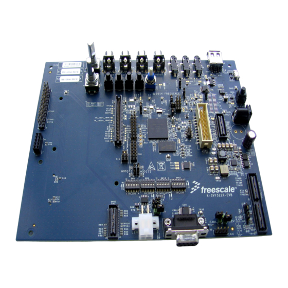
Four “Video In” (RCA “phono”) inputs with direct connection to MCU video ADC. • Unified 24-bit DCU connector (QSH-060-01-L-D-A) with analog and I C support for basic touch screen operation; matches Freescale LCD and HDMI daughtercards. • MLB daughtercard connector. EVB-VF522R3 Platform User’s Guide, Rev. 0, 11/2014 Freescale Semiconductor, Inc. - Page 4 Power must be removed from the EVB prior to: • Removing or installing daughtercards or other connectors. • Reconfiguring the board jumpers or switches. Figure 1. Freescale Automotive Evaluation Board (EVB) overview EVB-VF522R3 Platform User’s Guide, Rev. 0, 11/2014 Freescale Semiconductor, Inc.
-
Page 5: Configuration Overview
Figure 3 below. Explained are the power, reset, clocks, and debug configuration settings, which are the minimum required to power on the EVB. Figure 2. EVB functional blocks (top view) EVB-VF522R3 Platform User’s Guide, Rev. 0, 11/2014 Freescale Semiconductor, Inc. -
Page 6: Power Management Scheme
A standard 2.1 mm barrel connector type is used. Care must be taken to ensure the correct polarization as shown in Figure 4 below. Figure 4. 2.1 mm power connector EVB-VF522R3 Platform User’s Guide, Rev. 0, 11/2014 Freescale Semiconductor, Inc. - Page 7 When the external power supply fails, the Secure Real-Time Clock (SecureRTC) module of the MCU operates from the on-board coin cell battery. Its holder accommodates a 20 mm diameter 3V lithium-ion EVB-VF522R3 Platform User’s Guide, Rev. 0, 11/2014 Freescale Semiconductor, Inc.
- Page 8 3.3V (to test low-power applications without 1.5V rail, e.g. without DDR); in this case, the optional diodes D2 and D3 shall be populated. Refer to the AN4807 Application Note for details. Figure 6. MCU core power EVB-VF522R3 Platform User’s Guide, Rev. 0, 11/2014 Freescale Semiconductor, Inc.
- Page 9 The optional linear 3.3V regulator (U513) does not have an ON/OFF feature Figure 7. Analog MCU supplies Measuring MCU power consumption The EVB design provides means for measuring currents in the major MCU power rails. EVB-VF522R3 Platform User’s Guide, Rev. 0, 11/2014 Freescale Semiconductor, Inc.
- Page 10 0-Ohm resistor in the R28 location (see Figure 6 Table 15) is replaced with a current-sense one. For user’s convenience, eight 0.02-Ohm 1% current-sense resistors are provided on the board (see Figure EVB-VF522R3 Platform User’s Guide, Rev. 0, 11/2014 Freescale Semiconductor, Inc.
- Page 11 Numerous power rails have series “shorts” (e.g., SH15 in the MPU SDRAM controller power rail)–exposed copper footprints consisting of two pads shorted with a trace. If required, the trace can be cut and a current-sense resistor soldered onto the pads. Refer to the EVB-VF522R3 Schematic for details. 4.7.5 Powering EVB peripherals The power-routing options detailed in Section 4.6, “MCU supply...
-
Page 12: Clocking Scheme
3.3V-rated output is connected to a 1.1V-rated MCU input for applications requiring a high-quality clock source. When Y2 is used, the Y3-based circuit (Y3, C63, C66, and R640) shall be unpopulated. EVB-VF522R3 Platform User’s Guide, Rev. 0, 11/2014 Freescale Semiconductor, Inc. -
Page 13: Mcu Reset Block
• 3.3V-based power-on reset with ~ 200ms active timeout (delay), • Manual reset (using SW7), • Reset caused by the JTAG TRST signal (see Section 9, “Debug interfaces (P15, P16)”). EVB-VF522R3 Platform User’s Guide, Rev. 0, 11/2014 Freescale Semiconductor, Inc. -
Page 14: Peripheral Reset-Control Multiplexer
When reset, all the outputs are in the high-impedance state; however, thanks to pull-down resistors on the used outputs, the controlled peripherals are staying in the reset state until the outputs are actively driven by the MCU over the I C bus (address 0x30). EVB-VF522R3 Platform User’s Guide, Rev. 0, 11/2014 Freescale Semiconductor, Inc. -
Page 15: Mcu Reset Boot Configuration
Reset configuration is read from the RCON switches when BOOTMOD[0..1] is set to 10 and ignored for the rest of the values (see Table 15). Figure 13. RCON slide switches EVB-VF522R3 Platform User’s Guide, Rev. 0, 11/2014 Freescale Semiconductor, Inc. -
Page 16: Debug Interfaces (P15, P16)
SW11[8..1] RCON[31..24] SW10[8..1] RCON[23..16] SW9[8..1] RCON[15..8] SW8[8..1] RCON[7..0] Debug interfaces (P15, P16) Two debugging JTAG headers are provided on the EVB-VF522R3 board (pinout shown in Figure Table 4, and Table • Standard 20-pin (P15) • Cortex 10-pin (P16) Figure 14. Debug headers Table 4. -
Page 17: On-Board Memory
DDR3 self-refresh (low-power) mode is supported even when Vybrid is in any of the LPSTOPx modes, in which its I/Os are switched into a high-impedance mode. The on-board pull-up on DDR_RESET and pull-down on DDR_CKE lines keep the DDR3 chip in self-refresh mode. EVB-VF522R3 Platform User’s Guide, Rev. 0, 11/2014 Freescale Semiconductor, Inc. -
Page 18: Communication Interfaces
The memory type installed does not use the Vybrid DQSx signal lines, so these are disconnected by default and Vybrid uses them as GPIOs. Refer to the EVB-VF522R3 Schematic for details. The following Vybrid features can be implemented on the EVB: •... - Page 19 Connected to a standard 9-way female D-type connector (P26) allowing a direct connection to a PC or terminal, pinout being shown in Figure • Providing no hardware flow control support. Figure 17. RS232 physical interface connector EVB-VF522R3 Platform User’s Guide, Rev. 0, 11/2014 Freescale Semiconductor, Inc.
- Page 20 DOC-01898 document; a relevant daughtercard, e.g. IMXAI2ETH-SMSC (see Figure 20), can be plugged into it, • Pins of the other one are used for other functions EVB-VF522R3 Platform User’s Guide, Rev. 0, 11/2014 Freescale Semiconductor, Inc.
- Page 21 USB1 - “Type A Host” connector (P1). They are powered through jumpers J4 and J7 as shown in Figure 21, their configuration setting being described in Table Figure 21. MCU USB interfaces power EVB-VF522R3 Platform User’s Guide, Rev. 0, 11/2014 Freescale Semiconductor, Inc.
-
Page 22: Video Interfaces
• The Freescale TFT LCD daughtercards, e.g., the 7-inch LCD-WVGA-7IN-1 one, • The Freescale HDMI daughtercards, e.g., MCIMXHDMICARD shown in Figure Figure 23. HDMI daughtercard EVB-VF522R3 Platform User’s Guide, Rev. 0, 11/2014 Freescale Semiconductor, Inc. -
Page 23: Audio Blocks
Section 14.8, “Bluetooth daughtercard header (J5)”, respectively. 13.1 Microphones A stereo pair of miniature on-board microphones is: • Placed at the bottom left (U503) and bottom right (U504) of the EVB, EVB-VF522R3 Platform User’s Guide, Rev. 0, 11/2014 Freescale Semiconductor, Inc. - Page 24 DSP is reset until the line is actively driven by the MCU via the Peripheral Reset-Control Multiplexer. EVB-VF522R3 Platform User’s Guide, Rev. 0, 11/2014 Freescale Semiconductor, Inc.
-
Page 25: User I/O And Control
EVB (see Table 6 Table Table 6. Connector P11 (analog) Signal Pin No Pin No Signal ADC0SE8 ADC1SE8 ADC0SE9 ADC1SE9 DACO0 DACO1 REF_GND REF_GND EVB-VF522R3 Platform User’s Guide, Rev. 0, 11/2014 Freescale Semiconductor, Inc. - Page 26 GPIO for the center button push (see Table Table 8. Incremental encoders Encoder GPIO FTM Channels FB_AD24 CHA – FB_AD19 (QD_PHA) CHB – FB_AD18 (QD_PHB) FB_AD25 CHA - FTM1CH0 (QD_PHA) CHB - FTM1CH1 (QD_PHB) EVB-VF522R3 Platform User’s Guide, Rev. 0, 11/2014 Freescale Semiconductor, Inc.
- Page 27 MCU via the Peripheral Reset-Control Multiplexer. CAUTION Ensure that the EVB is powered OFF prior to fitting or removal of the daughtercard. EVB-VF522R3 Platform User’s Guide, Rev. 0, 11/2014 Freescale Semiconductor, Inc.
- Page 28 Ensure that the EVB is powered OFF prior to fitting or removal of the daughtercard. 14.6 C Connectors and headers Refer to the EVB-VF522R3 Schematic for details. 14.6.1 C Daughtercard connector with 3.3V power (P17) A 10-pin 0.1” pitch connector (P17) enables connection of a custom-made 3.3V-powered daughtercard...
- Page 29 There is a 0.1-inch pitch generic CD header fitted on the EVB as described in Table Table 12. Generic CD header Signal Pin No Pin No Signal 3.3V 5.0V SAI2_RX_BCLK C3_SCL SAI2_RX_DATA C3_SDA SAI2_RX_SYNC RESET MCLK (from DSP) EVB-VF522R3 Platform User’s Guide, Rev. 0, 11/2014 Freescale Semiconductor, Inc.
- Page 30 Figure 27. Bluetooth daughtercard Table 13. Bluetooth daughtercard header Signal Pin No Pin No Signal SAI0_RX_DATA SAI0_TX_BCLK SAI0_TX_SYNC SAI0_TX_DATA SCI0_TX SCI0_RX SDHC1_CLK SCI0_CTS SCI0_RTS SDHC1_CMD FB_AD20 (SDHC1_CD) RESET SDHC1_A_DATA0 SDHC1_DATA1 SDHC1_A_DATA2 SDHC1_DATA3 EVB-VF522R3 Platform User’s Guide, Rev. 0, 11/2014 Freescale Semiconductor, Inc.
-
Page 31: Mcu I/O Connections And Pin Usage
BOOTMOD[1] DCU0_HSYNC RCON RCON[0..17] DCU0_R/G/B[2..7] RCON[18..20] RMII0_x MAC (Ethernet) RCON[21,23] SAI0_x Bluetooth RCON22 SAI0_RX_SYNC Preset SW3 RCON[24..29] SAI1_x (all) DSP (including dedicated Flash), Microphones, Touchscreen RCON[30..31] FTM0CH[1..2] QuadSPI1 (Flash C) EVB-VF522R3 Platform User’s Guide, Rev. 0, 11/2014 Freescale Semiconductor, Inc. - Page 32 P11 (unused analog GPIOs) Left Encoder FTM1CH[0..1] FB_AD25 GPIO P14 (unused digital GPIOs) Right Encoder FB_AD[18,19] FB_AD24 GPIO P14 (unused digital GPIOs) Preset Switches FB_AD[29..31] GPIO P14 (unused digital GPIOs) SAI0_RX_SYNC GPIO RCON22 EVB-VF522R3 Platform User’s Guide, Rev. 0, 11/2014 Freescale Semiconductor, Inc.
-
Page 33: Configuration Settings
EVB state if required. Table 15. Configuration settings Device Function Position Legend Description “AUDIO IN” To MCU ADC routing To DSP Removed To none EVB-VF522R3 Platform User’s Guide, Rev. 0, 11/2014 Freescale Semiconductor, Inc. - Page 34 J18, J19 Interface Touchscreen selected Removed None selected LIN interface power Removed From Molex connector source Fitted Local CAN termination control Removed Fitted Power from EVB over CAN Removed cable Fitted EVB-VF522R3 Platform User’s Guide, Rev. 0, 11/2014 Freescale Semiconductor, Inc.
- Page 35 * Can be used for current measurements if replaced with a current measuring device. ** Can be used for current measurements if replaced with a current-sense resistor. Default settings for jumpers only are shown in Figure EVB-VF522R3 Platform User’s Guide, Rev. 0, 11/2014 Freescale Semiconductor, Inc.
-
Page 36: Getting Started
Figure 28. Default jumper settings 17 Getting started To get started, follow steps provided in the EVB-VF522R3 Quick Start Guide. 18 Reference documents More information on the Vybrid family and EVB System is provided in the documents below, which can be found in the documentation sections of freescale.com/Vybrid and freescale.com/EVB-VF522R3. -
Page 37: Revision History
Revision history • DOC-01898: Ethernet Board-to-Board Connector Assignment. 19 Revision history Revision Date Comment 11/2014 Initial Release EVB-VF522R3 Platform User’s Guide, Rev. 0, 11/2014 Freescale Semiconductor, Inc. - Page 38 How to Reach Us: Information in this document is provided solely to enable system and software implementers to use Freescale products. There are no express or implied copyright Home Page: licenses granted hereunder to design or fabricate any integrated circuits based on the freescale.com information in this document.
Need help?
Do you have a question about the EVB-VF522R3 and is the answer not in the manual?
Questions and answers