Advertisement
Quick Links
Calibration Station
INDIVIDUAL GASES - INSTALLATION & USE
GMI Part Number: 67109 (67109Q)
The automatic calibration station, Part No.
67109 with 6mm. fittings (67109Q with
fittings), provides a safe and convenient method
of calibrating the GT series instrument. The
calibration station for individual gases should
be mounted on a vertical surface for best results.
Wall mounting the calibration station:
If wall mounting calibration station, hold unit
complete with backplate in required location on
wall then, using backplate as a template, mark
(4) hole positions on wall. Use (4) suitable screws
(and rawlplugs if positioning the unit on a brick
wall) to secure. The calibration station backplate
can be removed, if required, to mark hole
positions more accurately. Refer also to paragraph
3 below: permanent power cable connection.
Calibration
67109(Q):
There are three methods of providing power
to the GT series calibration station 67109(Q).
1. Via a 12V PSU (GMI Part No. 12444)
located in a socket on the top face of
the
calibration
2. Via a 12V vehicle power supply (GMI Part
No. 12988) also located in a socket on the top
face of the calibration station. Refer to Fig. 2.
Fig. 2 12V Power Socket - Top
station
power
station.
Refer
to
1
/
inch
4
supply
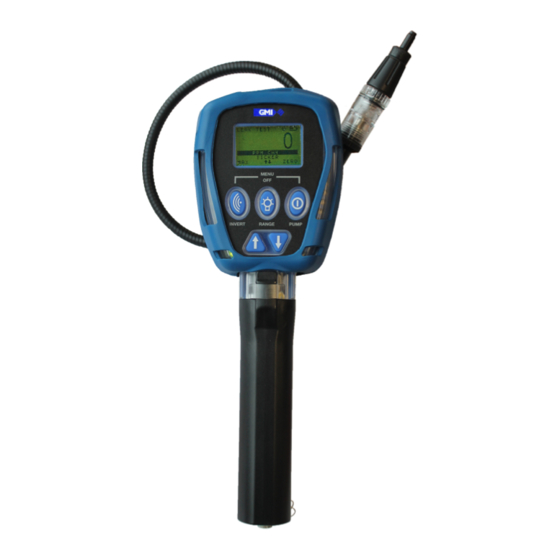
Fig. 1 GT series instrument located in
(Individual Gases) Calibration Station
3. Via permanent 12V power supply cable.
This
requires
wall mounting the unit, procedure as follows:
a) Remove (6) screws that attach backplate to the
Fig.
2.
calibration station.
b) Remove blanking plug from underside of unit.
c) Fit 20mm. (
Note max. wire cross section area = 2.5mm
d) Connect permanent 12V power supply cable to
J25 connector on calibration station PCB. (observe
correct polarity). Refer to Fig. 3.
e) Replace backplate then secure using (6) screws.
Calibration station power supply 67611(Q):
The GT series calibration station 6761 1(Q) is powered
via 12V power supply cable from PC Controller
unit. The PC Controller unit is powered via mains
cable (both cables are supplied with the unit).
1. The 12V power supply cable from PC controller is
located in a socket on the top face of the calibration
Fig. 2 12V Power Socket - Top station. Refer to Fig. 2.
removal
of
backplate
3
/
in.) cable gland - size to suit cable.
4
before
2
Advertisement

Related Manuals for Teledyne GT Series


Summary of Contents for Teledyne GT Series
- Page 1 Refer to Fig. 3. e) Replace backplate then secure using (6) screws. Calibration station power supply 67611(Q): The GT series calibration station 6761 1(Q) is powered via 12V power supply cable from PC Controller unit. The PC Controller unit is powered via mains cable (both cables are supplied with the unit).
- Page 2 As an ISO9001 approved company, Teledyne GMI Ltd’s quality assurance programmes demand the continuous assessment and improvement of all Teledyne GMI products. Information in this leaflet could thus change without notification and does not constitute a product specification. Please contact Teledyne GMI or their representative if you require more details.