Table of Contents
Advertisement
Quick Links
Advertisement
Table of Contents

Related Manuals for Artesyn Embedded Technology SharpMedia PCIE-8120


Summary of Contents for Artesyn Embedded Technology SharpMedia PCIE-8120
- Page 1 SharpMedia™ PCIE-8120 Installation and Use P/N: 6806800R89F November 2016...
- Page 2 © Copyright 2016 Artesyn Embedded Technologies, Inc. All rights reserved. Trademarks Artesyn Embedded Technologies, Artesyn and the Artesyn Embedded Technologies logo are trademarks and service marks of Artesyn Embedded Technologies, Inc. All other names and logos referred to are trade names, trademarks, or registered trademarks ©...
-
Page 3: Table Of Contents
SharpMedia PCIE-8120 Software Package ........ - Page 4 SharpMedia PCIE-8120 Card Edge Connector ........
- Page 5 Contents B.8.1 Card Power Management ........... . . 79 B.8.2 Interfaces and S/W control .
- Page 6 Install and Configure PCIE-8120 in MaxCore ..........107 Installing Software and Configuring a SharpMedia PCIE-8120 Card in MaxCore ... . 107 Related Documentation .
- Page 7 Table A-1 SharpMedia PCIE-8120 Card Edge Connector Pin out ....... 62 Table A-2 ATX PWR Pinout .
- Page 8 List of Tables SharpMedia™ PCIE-8120 Installation and Use (6806800R89F)
- Page 9 Figure B-8 Port Mapping SharpMedia PCIE-8120-A04 ....... . . 76 Figure B-9 Port Mapping SharpMedia PCIE-8120-A12-N/V12-N .
- Page 10 List of Figures SharpMedia™ PCIE-8120 Installation and Use (6806800R89F)
-
Page 11: About This Manual
Appendix F, Install and Configure PCIE-8120 in MaxCore, on page 107 describes how to install the required SharpMedia PCIE-8120 RPMs and how to configure a PCIE-8120 card in a MaxCore system. Related Documentation on page 115 provides a listing of related product documentation, ... - Page 12 About this Manual About this Manual Abbreviations This document uses the following abbreviations: Abbreviation Definition Application Programmers Interface Advanced Technology Extended Ball Grid Array Card Electro Mechanical CISPR Comité Internationale Spécial des Perturbations Radioelectrotechnique CPLD Complex Programmable Logic Device Double Data Rate DHCP Dynamic Host Configuration Protocol DRAM...
- Page 13 About this Manual Abbreviation Definition NVRAM Non-Volatile Random Access Memory OCTVOC Internal code name for Octasic DSP 1010 OCTVOC2 Internal code name for Octasic DSP 2224M (equipped on PCIE-8120) OCTVOC2_EB Internal code name for Octasic Evaluation Board equipped with DSP 2224M Peripheral Component Interconnect PCI-E...
- Page 14 About this Manual About this Manual Conventions The following table describes the conventions used throughout this manual. Notation Description 0x00000000 Typical notation for hexadecimal numbers (digits are 0 through F), for example used for addresses and offsets 0b0000 Same for binary numbers (digits are 0 and 1) bold Used to emphasize a word Used for on-screen output and code related elements...
- Page 15 About this Manual Notation Description Indicates a hazardous situation which, if not avoided, could result in death or serious injury Indicates a hazardous situation which, if not avoided, may result in minor or moderate injury Indicates a property damage message No danger encountered.
- Page 16 About this Manual About this Manual SharpMedia™ PCIE-8120 Installation and Use (6806800R89F)
-
Page 17: Safety Notes
Safety Notes This section provides warnings that precede potentially dangerous procedures throughout this manual. Instructions contained in the warnings must be followed during all phases of operation, service, and repair of this equipment. You should also employ all other safety precautions necessary for the operation of the equipment in your operating environment. - Page 18 Safety Notes Operation of this equipment in a residential area is likely to cause harmful interference in which case the user will be required to correct the interference at his own expense. Changes or modifications not expressly approved by Artesyn Embedded Technologies Embedded Communications Computing could void the user's authority to operate the equipment.
- Page 19 Safety Notes Installation Damage of Circuits Electrostatic discharge and incorrect installation and removal of the product can damage circuits or shorten their life. Before touching the product or electronic components, make sure that your are working in an ESD-safe environment. Product Damage Incorrect installation of the product can cause damage of the product.
- Page 20 Safety Notes SharpMedia™ PCIE-8120 Installation and Use (6806800R89F)
-
Page 21: Sicherheitshinweise
Sicherheitshinweise Dieses Kapitel enthält Hinweise, die potentiell gefährlichen Prozeduren innerhalb dieses Handbuchs vorrangestellt sind. Beachten Sie unbedingt in allen Phasen des Betriebs, der Wartung und der Reparatur des Systems die Anweisungen, die diesen Hinweisen enthalten sind. Sie sollten außerdem alle anderen Vorsichtsmaßnahmen treffen, die für den Betrieb des Produktes innerhalb Ihrer Betriebsumgebung notwendig sind. - Page 22 Sicherheitshinweise Das Produkt wurde in einem Artesyn Embedded Technologies Standardsystem getestet. Es erfüllt die für digitale Geräte der Klasse A gültigen Grenzwerte in einem solchen System gemäß den FCC-Richtlinien Abschnitt 15 bzw. EN 55022 Klasse A. Diese Grenzwerte sollen einen angemessenen Schutz vor Störstrahlung beim Betrieb des Produktes in Gewerbe- sowie Industriegebieten gewährleisten.
- Page 23 Sicherheitshinweise Überhitzung und Beschädigung des Produktes Betreiben Sie das Produkt ohne Zwangsbelüftung, kann das Produkt überhitzt und schließlich beschädigt werden. Bevor Sie das Produkt betreiben, müssen Sie sicher stellen, dass das Gerät über eine Zwangskühlung verfügt. Fehlerhafter Datenbestand Wenn sie die Spannungsversorgung des Produkts abschalten, während Programmdaten im Flashspeicher aktualisiert, werden, können diese Daten nicht korrekt gespeichert werden.
- Page 24 Sicherheitshinweise Installation Beschädigung von Schaltkreisen Elektrostatische Entladung und unsachgemäßer Ein- und Ausbau des Produktes kannSchaltkreise beschädigen oder ihre Lebensdauer verkürzen.Bevor Sie das Produkt oder elektronische Komponenten berühren, vergewissern Sie sich, daßSie in einem ESD- geschützten Bereich arbeiten. Beschädigung des Produktes Fehlerhafte Installation des Produktes kann zu einer Beschädigung des Produktes führen.
-
Page 25: Introduction
PCI Express slots. The PCIE-8120 is an Octasic Digital Signal Processor (DSP) based PCI Express card running Vocallo MGW firmware. The SharpMedia PCIE-8120 acceleration engine can take the place of additional servers when adding high density voice and video processing to an application.The PCIE-8120 card is... -
Page 26: Software Components
Introduction Card can operate either from slot power or from an external connector for NEBS variant. Power envelope of 75 Watts for > 4 DSP slot powered versions. DSP core: – Multicore Octasic OCT2224M DSPs running Vocallo –... -
Page 27: Figure 1-1 Software Diagram
Introduction The following figure provides the architectural overview of the PCIE-8120 software: Figure 1-1 Software Diagram The PCIE-8120 support software configures the PCIE-8120 card, sets up the switches to which DSPs are connected and initializes the card. The user application manages the Vocallo media processing services through a packet based Application Programmers Interface (API). -
Page 28: Standard Compliances
Introduction Standard Compliances This product is designed to meet the following standards when installed in an appropriate system environment. Table 1-1 Standard Compliances Standard Description UL 60950-1 Legal safety requirements EN 60950-1 IEC 60950-1 CAN/CSA C22.2 No 60950-1 CISPR 22 EMC requirements (legal) on system level (predefined Artesyn Embedded Technologies system) CISPR 24... -
Page 29: Ordering/Support Information
Slot PCIE-8120-V08 Slot PCIE-8120-A12-N PCIE-8120-V12-N 1. In exceptional condition at @55°C system environment for max. 96 hours. Mechanical Data The outline of the SharpMedia PCIE-8120 card and its dimensions are shown in Figure 1-2. SharpMedia™ PCIE-8120 Installation and Use (6806800R89F) -
Page 30: Figure 1-2 Mechanical Layout
Introduction The PCB size dimensions are in accordance with the PCI-SIG CEM specifications: Height=101.80 mm Length=304.50 mm Figure 1-2 Mechanical Layout 101.80 85.40 40.55 29.95 4.85 C250 R144 R136 R135 U4203 R313 R327 R314 R316 R315 R259 R350 U1001 R258 D5300... -
Page 31: Functional Description
Ethernet switches. For more details, see the block diagrams in SharpMedia PCIE-8120 Hardware Description on page A comprehensive host-based Media Processing Application Programmers Interface is provided. This is used to configure and execute voice and video stream processing functions on the DSPs. - Page 32 Functional Description SharpMedia™ PCIE-8120 Installation and Use (6806800R89F)
-
Page 33: Hardware Preparation And Installation
Chapter 3 Hardware Preparation and Installation In this chapter, you can find information on the following topics: Unpacking and inspecting the card. Environmental, thermal, and power requirements. Card installation and removal. Unpacking and Inspecting the Card Damage of Circuits Electrostatic discharge and incorrect installation and removal of the card can damage circuits or shorten their life. -
Page 34: Environmental, Thermal, And Power Requirements
Hardware Preparation and Installation 3. Remove the desiccant bag shipped with the card and dispose of it according to your country’s legislation. The card is thoroughly inspected before shipment. If any damage has occurred during transportation please contact our Contact Center immediately. Environmental, Thermal, and Power Requirements The following environmental, thermal, and power requirements are applicable to the card. -
Page 35: Power Requirements
Hardware Preparation and Installation Table 3-1 Environmental and Thermal Requirements Requirement Operating Non-Operating Temperature 0°C to 40°C system ambient, -40°C to +70°C exceptional max. 55°C for max. 96 hours Forced Air Flow Recommended >0.5m/s Temp. Change +/-0.25°C/min +/-0.25°C/min Rel. Humidity 5% to 90% non-condensing 5% to 95% non-condensing Vibration... -
Page 36: Card Installation And Removal
Use the following steps to install the SharpMedia PCIE-8120 card into the rack mount server: 1. Use anti-static pads and attach an ESD strap to your wrist. Attach the other end of the ESD strap to an electrical ground (refer to Unpacking Guidelines). -
Page 37: Removal Procedure
2. Remove any cable that is connected to the card. 3. Power off the system before removing the card. 4. Gently pull the SharpMedia PCIE-8120 card to disconnect it from the connectors. Continue to slide the card outward along the guide rails from the rack mount server. - Page 38 Hardware Preparation and Installation SharpMedia™ PCIE-8120 Installation and Use (6806800R89F)
-
Page 39: Software Installation
Chapter 4 Software Installation Prerequisites Before installing the PCIE-8120 card, ensure the following software packages are installed on your host machine: – vconfig (This package is not required for CentOS 7.x/ RHEL 7.x) – xinetd – net-tools – dhcp –... -
Page 40: Installing Software
./octasic-sdk-3.00.01- B981.el7.centos.x86_64.rpm After the installation, add /opt/bladeservices/bin to the PATH variable of the user. export PATH = $PATH: /opt/bladeservices/bin SharpMedia PCIE-8120 Software Package LIBRARY The library is a C-programming interface provided for software development that provides access to the resources on the card.The components that can be accessed are: –... -
Page 41: Configuration Overview
Software Installation Installing the PCIE-8120 RPM creates the following folders and files in /opt/bladeservices. Folder Description Contains tools. /opt/bladeservices/bin Contains documentation. /opt/bladeservices/share/doc/html Includes SharpMedia PCIE-8120 /opt/bladeservices/include header files. Contains SharpMedia PCIE-8120 /opt/bladeservices/lib library. Contains SharpMedia PCIE-8120 /opt/bladeservices/modules kernel module. -
Page 42: Initialization Of The Card
Software Installation DSPs are held in reset waiting for the rest of the system to start up. When the DSPs are taken out of reset, DSPs send out DHCP DISCOVER messages to get a firmware image. Once the DSP retrieves its networking information from the DHCP-server, a firmware image is loaded to the DSP. -
Page 43: Starting The Dsps
Software Installation The following message displays when executing octSetup for the first time and can be ignored: SELINUX: labeling directory /var/lib/tftpboot with tftpdir _rw_t …libsemanage.dbase_llist_query: could not query record value (No such file or directory). 2. Execute the below command (If you want to setup a different IP-address): # octSetup --ipaddr=dd.dd.dd.dd Configuring the IP-address: The default format of <IP-address>... -
Page 44: Command Line Utility
Software Installation Now, the DSPs are taken out of reset. The DSP starts loading and executing the image. You can check the tftpboot directory given above, to evaluate whether DSPs have successfully loaded its image or not. The tftp load process is successful, if every DSP has stored its MAC address- specific boot status file in tftpboot directory. - Page 45 Software Installation Table 4-1 Commands (continued) Command Description Displays status of ports. -s|--status [<port>] Performs board-specific initialization. --init Prints list of available devices. --listdev[=names] Lists configured port(s). --listport [<port>|detail|dsp] Enable/disable auto-negotiation. --aneg <port> <on|off> Restarts auto-negotiation. --anrestart <port> Set forwarding mask. --fwdmask <port>...
- Page 46 Software Installation Table 4-1 Commands (continued) Command Description Controls the DSPs connected to switch. --dspctrl=<cmd> <all|<dsps...>> [<key>] cmd: Take DSPs out of reset. down Put DSPs into reset. Retrieves MAC-addresses of the DSPs. status Shows whether the DSPs are in reset. addboot Adds DSPs to boot VLAN.
- Page 47 Software Installation Table 4-1 Commands (continued) Command Description Controls the reset functionality of switch. --bcmreset=<cmd> cmd: Resets the switch. Brings the switch out of reset. --arltblclr <vid> Clears ARL table entries for specified VID. Controls flow-control for the specified port. --flowctrl=<cmd>...
- Page 48 Software Installation octmezz --dev=MSW0 -s Port Details Lists the port details of MSW0 device octmezz --dev=MSW0 --listport detail vlans Lists the vlans of MSW0 device octmezz --dev=msw0 --listvlans DSP Status Displays the status of DSPs present on the PCIE8120 board. octmezz --dev=msw0 --dspctrl=status all Sensor Devices Lists the sensor devices present on the PCIE-8120 board hosting cpld0 device.
-
Page 49: Perl Utilities
Software Installation 4.4.5 PERL Utilities The PCIE-8120 software provides following PERL utilities: pcie8120-boot-status: Provides users with the information about the boot status of DSPs on PCIE8120. pcie8120-dsp-boot-setup: This utility is internally used by octSetup utility for configuring and creating the boot environment for DSPs to boot from host system. pcie8120-listdev: Lists all the available PCIE8120 cards on the host system along with the ... -
Page 50: Executing Demo
Software Installation 4.5.1 Executing Demo The demo is used to configure the maximum number of VOIP connections on the PCIE-8120. For more information, see 12dsp_audio_transcode_net_api.c file at /opt/octasic/application/sample/octvoc/12dsp_audio_transcode_net_a pi/source location. To start the demo, execute the following: # cd /opt/octasic/application/sample/octvoc/12dsp_audio_transocde_net_a To execute the demo, find MAC-address of your local interface to the card. - Page 51 Software Installation The first argument defines the MAC of the MSW network interface. The second argument defines the number of iterations. In the example above, just one loop is executed. To run continuously use -1 for the number of iterations: # ./12_dsp_audio_transcode_net_api 00:80:42:2C:7B:D8 -1 The test passes, if all of the “Err”, “Drop”, “Slip”...
- Page 52 Software Installation | TxInBadPktPayloadCnt | TxTimestampGapCnt | TxTdmWriteErrCnt | RxToneDetectedCnt | RxToneRelayEventPktCnt | RxToneRelayUnsupportedCnt | TxToneRelayEventPktCnt | TxApiEventCnt | TxNoRtpEntryPktDropCnt | ConnectionWaitAckFlag | RxMipsProtectionDropCnt | TxMipsProtectionDropCnt | CallTimerMsec : 61665 Note: The loop counter increments, each time the DSP 00 displayed. If any of the “Err”, “Drop”, “Slip”...
-
Page 53: Application Development
Precompiled DSP firmware image file Vocallo MGW SDK to match firmware image Artesyn Embedded Technologies Demo application configuring all 12 DSPs on PCIE-8120 SharpMedia PCIE-8120 configuration files (csv and octvocfs.tar) DSP firmware creation tool executable Audio license file ... -
Page 54: Octasic Linux Tools
Documentation from octasic is provided inside the tool folders. Octasic DSP Firmware image Every Octasic DSP on the SharpMedia PCIE-8120 card loads the firmware code and it executes directly from external DRAM. The firmware image is loaded in the following way:... - Page 55 Application Development Boot status can be read by evaluating the stage1 and stage2 specific boot process progress counter, version register, error status and info field. DSP writes its boot status into boot_status.<MAC-address> file located in the TFTP root directory (defaults are /var/lib/tftpboot or /tftproot).
-
Page 56: Octasic Dsp Firmware Image Creation
# cd /opt/octasic/hardware/octvoc2/oct2200/bootfile opt/octasic/bin/oct2200_boot_img_gen octvocmgw.citadelle.csv oct2200citadelle.img Always use the octvocmgw.citadelle.csv file provided with the RPM for creating DSP images for SharpMedia PCIE-8120. To set up the card with its board-specific hardware, octvocmgw.citadelle.csv file is required. SharpMedia™ PCIE-8120 Installation and Use (6806800R89F) -
Page 57: Figure 5-2 Files In Firmware Build
Application Development The following figure shows the files included in a firmware build and the files that should be configured with reference to the application: Figure 5-2 Files in firmware build The input file octvocmgw.citadelle.csv includes a TAR file called octvocfs.tar. The tar file contains two files: license file (audio license) octvc1.lic.asc ... - Page 58 Application Development The file octvc1_config.arg located in folder octvocmgw specifies the hardware specifics of the SharpMedia PCIE-8120. <EthernetPort PortNum="0"> <PortInterface Value="EMAC2"/> <EthernetPort PortNum="1"> <PortInterface Value="EMAC0"/> <TdmModule> <TdmDisabledFrameSrcValue="0"/> <FramePolarity Value=""/> <FrameSamplingMode Value=""/> <DataSamplingMode Value=""/> <FromTdmTsstBufferSizeMs Value=""/> <ToTdmTsstBufferSizeMs Value=""/> <FromTdmBitOffset Value=""/> <ToTdmBitOffset Value=""/>...
-
Page 59: 12Xdsp Audio Transcode Demo
Application Development <MaxNumVideoRxSd Value="1"/> <MaxNumVideoRx720p Value="0"/> <MaxNumVideoRx1080p Value="0"/> <MaxNumVideoBufferQcif Value="224"/> octvc1._config.arg file is provided as an example for 12dsp audio application. Align the resources of the DSP based on your application. Also, keep the hardware-specific configuration parameters (port interface, ... - Page 60 Application Development For details about how to use the demo, see README_max_channel_tests.txt file at the /opt/octasic/application/sample/octvoc/12dsp_audio_transcode_net_a pi location. SharpMedia™ PCIE-8120 Installation and Use (6806800R89F)
-
Page 61: Sharpmedia Pcie-8120 External Connectors
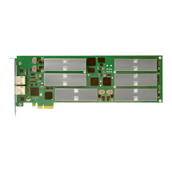
SharpMedia PCIE-8120 External Connectors This section describes the pin assignments and signals for the connectors on the SharpMedia PCIE-8120 card. The following figure shows the top and bottom view layout of the SharpMedia PCIE-8120 card. Figure A-1 SharpMedia PCIE-8120 Primary and Secondary Layout... -
Page 62: Sharpmedia Pcie-8120 Card Edge Connector
SharpMedia PCIE-8120 External Connectors SharpMedia PCIE-8120 Card Edge Connector The following table provides pin assignment for the SharpMedia PCIE-8120 card edge connector. Table A-1 SharpMedia PCIE-8120 Card Edge Connector Pin out Side B Side A Name Description Name Description +12V... -
Page 63: J1/J2 External Ethernet Connector Status Leds (Not Available On -N Versions)
SharpMedia PCIE-8120 External Connectors Table A-1 SharpMedia PCIE-8120 Card Edge Connector Pin out (continued) Side B Side A Name Description Name Description PETp1 Transmitter differential pair, RSVD Reserved Lane 1 PETn1 Ground Ground PERp1 Receiver differential pair, Lane 1 Ground... -
Page 64: P2 External Atx 6-Pin Power Connector (Only On -N Versions)
Ground Sense Ground Debug Connectors The SharpMedia PCIE-8120 card is equipped with several debug ports. The debug ports allow DSP/MFA,CPLD/FPGA programming, and JTAG/BSCAN functionality. P4201 serial port MFA: RS232 style debug port for the MFA application. P5001 OCT-SDBI2 debug port: The Octasic Pod requires an adapter cable for the micro- ... -
Page 65: P3 Fan Unit Connector (Optional Component)
SharpMedia PCIE-8120 External Connectors P3 Fan Unit Connector (Optional component) The SharpMedia PCIE-8120 card supports a heat sink assembly that is equipped with a fan or blower unit. A three pin header provides 12V supply for this purpose. An additional buffer circuitry allows for PWM fan speed control via the CPLD. - Page 66 SharpMedia PCIE-8120 External Connectors SharpMedia™ PCIE-8120 Installation and Use (6806800R89F)
-
Page 67: Sharpmedia Pcie-8120 Hardware Description
SharpMedia PCIE-8120 Hardware Description This section describes the key hardware components of the SharpMedia™ PCIE-8120 card. SharpMedia PCIE-8120 Card Block Diagrams The following figures provide an overview of the main function blocks of the SharpMedia PCIE- 8120 and how they are interconnected. -
Page 68: Figure B-2 Card Block Diagram Sharpmedia Pcie-8120-A04
SharpMedia PCIE-8120 Hardware Description Figure B-2 Card Block Diagram SharpMedia PCIE-8120-A04 SharpMedia™ PCIE-8120 Installation and Use (6806800R89F) -
Page 69: Figure B-3 Card Block Diagram Sharpmedia Pcie-8120-A12-N/V12-N
SharpMedia PCIE-8120 Hardware Description Figure B-3 Card Block Diagram SharpMedia PCIE-8120-A12-N/V12-N SharpMedia™ PCIE-8120 Installation and Use (6806800R89F) -
Page 70: Card Reset Architecture
SharpMedia PCIE-8120 Hardware Description Card Reset Architecture The following figure provides an overview of SharpMedia PCIE-8120 card reset architecture. Figure B-4 Card Reset Diagram 88E1512 88E1512 88E1111 88E1111 MSW-RST_N VSW-RST_N PERST-82580_N 12x DSPx-RST_N PERST_N PCIe x4 card-edge connector SharpMedia™ PCIE-8120 Installation and Use (6806800R89F) -
Page 71: Power Supply Architecture
SharpMedia PCIE-8120 Hardware Description All devices on the card that provide a dedicated reset input are connected to the CPLD to allow for individual reset control at start up or during runtime via host control. The PERST_N signal is propagated to the Ethernet network devices (NIC, Switch, PHY) to make the card behave like a standard NIC card. - Page 72 SharpMedia PCIE-8120 Hardware Description The SharpMedia PCIE-8120 uses seven DC/DC building blocks to provide the necessary operating voltages that are required by the devices on the board. Main voltage supply comes from the 12V card edge or ATX 6-Pin connector via the ...
-
Page 73: Card Clock Architecture
Ethernet NIC The SharpMedia PCIE-8120 uses Intel 82580EB/DB Gigabit Ethernet Controller to implement PCI Express connectivity and thereby provides access for the Host system towards the card's resources. This device supports up to four Ethernet ports with integrated MAC units and SGMII/SerDes interface. -
Page 74: Nv-Memory-Nic Configuration
B.6.1 Main Switch Unit (MSW) - BCM5396 The main switch unit (MSW) is available on all versions of the SharpMedia PCIE-8120 card and provides the basic connection between all DSP, NIC, MFA, and external Ethernet resources. B.6.2 Video Switch Unit (VSW) - BCM5396 The Video Switch Unit (VSW) is available on variants that provide additional network connection between DSP, NIC, MFA, and external Ethernet resources. -
Page 75: Ethernet Port Mappings
SharpMedia PCIE-8120 Hardware Description B.6.3 Ethernet Port Mappings The following figures show the port mappings of the Ethernet fabric on the individual variants of the SharpMedia PCIE-8120 card. Figure B-7 Port Mapping SharpMedia PCIE-8120-A12/V12 DSP ETH port numbers DSP0 DSP1... -
Page 76: Figure B-8 Port Mapping Sharpmedia Pcie-8120-A04
SharpMedia PCIE-8120 Hardware Description Figure B-8 Port Mapping SharpMedia PCIE-8120-A04 DSP ETH port numbers DSP0 DSP1 DSP2 DSP3 DSP4 DSP5 DSP6 DSP7 DSP8 DSP09 #2 #3 #2 #3 #2 #3 #2 #3 #2 #3 #2 #3 #2 #3 #2 #3... -
Page 77: Figure B-9 Port Mapping Sharpmedia Pcie-8120-A12-N/V12-N
SharpMedia PCIE-8120 Hardware Description Figure B-9 Port Mapping SharpMedia PCIE-8120-A12-N/V12-N DSP ETH port numbers DSP0 DSP1 DSP2 DSP3 DSP4 DSP5 DSP6 DSP7 DSP8 DSP09 DSP10 DSP11 #2 #3 #2 #3 #2 #3 #2 #3 #2 #3 #2 #3 #2 #3... -
Page 78: Media Flow Aggregator (Mfa) Unit
SharpMedia PCIE-8120 Hardware Description Media Flow Aggregator (MFA) Unit The SharpMedia PCIE-8120 is optionally equipped with an Octasic OCT1503 MFA FPGA. The purpose of the device is to aggregate an array of Ethernet devices (i.e., the OCT2224 DSP array) to form a single logical node. For more information on Octasic OCT1503 MFA FPGA OCT1503 MFA FPGA Specifications. -
Page 79: Card Power Management
B.8.1 Card Power Management The CPLD on the SharpMedia PCIE-8120 fulfills the functionality of a power management controller for the card. The power-up and power-down control is based on the input signals. Internal power good status, that is, 3.3V from PCIE slot is present and the device has ... -
Page 80: Card Variant Mod_Id
SharpMedia PCIE-8120 Hardware Description B.8.2.2 Card Variant MOD_ID The card provides a 4-bit wide H/W strapped ID (MOD_ID<3..0>). It is used to identify the variant of the card. Based on the variant, some settings in the CPLD are different or specific registers are not available. -
Page 81: Smbus And Pvt_I2C Bus
B.8.2.5 SMBus and PVT_I2C Bus The SharpMedia PCIE-8120 card provides connectivity to the PCI Express connector SMBus. Additionally, a private I2C bus (PVT_I2C) is available that accesses the onboard sensor devices. Both are connected to the CPLD to allow access to the sensor information via SMBus or through the Host system via MDIO. - Page 82 SharpMedia PCIE-8120 Hardware Description There are two temperature sensors on the PVT_I2C bus for monitoring the temperature on the card and the thermal behavior of the system. One sensor is placed on the mounting bracket side which is considered as the air outlet side. The other sensor is placed on the card retainer side which is considered as the air inlet side (see Figure "Temperature Sensor Location"...
-
Page 83: Figure B-11 Temperature Sensor Location
SharpMedia PCIE-8120 Hardware Description An additional temperature sensor is available at the SMBus in conjunction with the NIC device. It allows monitoring the temperature of the device. ADT7461 Device SMB address 0x4C Figure B-11 Temperature Sensor Location I/V/P Sensors A current and power monitor device is available on the PVT_I2C bus for surveillance purpose. - Page 84 SharpMedia PCIE-8120 Hardware Description Programmable alerts for – Power – Current – Voltage Alert_INT to CPLD Check the power consumption of the card with the command. An example is given below: # PCIE-8120-read-sensor PCIE-8120#0: t_inlet: 31°C t_outlet: 32.5°C ivp_volt: 11.9425V...
-
Page 85: Debug Led
SharpMedia PCIE-8120 Hardware Description Table B-2 Sensor alert default values Sensor type Minor Major Critical Inlet Temp >50°C >55°C >60°C Outlet Temp >55°C >70°C >80°C *** Delta Temp <5°C * >15°C > 0°C Card Power 12 OCT 60W@12V 65W@12V 70W@12V Supply Bus voltage <... -
Page 86: Table B-4 Led Error Code (For 3, 4, 5,6 And 7)
SharpMedia PCIE-8120 Hardware Description Table B-3 LED Error Code (For 0, 1 and 2) LED NUMBER DESCRIPTION Enable state-Onboard converters enabled Wait state-Power good status Wait state-Power-up sequencing Power good status and PERST_N deasserted N/A (shutdown) Table B-4 LED Error Code (For 3, 4, 5,6 and 7) -
Page 87: Cpld Upgrade
5. Powercycle the board. DSP Array The SharpMedia PCIE-8120 DSP Array can be populated with up to 12 instances of Octasic's DSP OCT2224M System-On-Chip device, which is specialized for media gateway applications. For more information on the Octasic DSP OCT2224M, refer to the OCT2200M Hardware Specification listed in Table "Related Specifications"... -
Page 88: Ddr3 Memory Subsystem
SharpMedia PCIE-8120 Hardware Description The OCT2224M is composed of five major subsystems: The Opus2 DSP subsystem The DDR Memory Subsystem The High-speed I/O Subsystem (Ethernet MAC Engines) The Resources Subsystem (GPIO) The Maintenance Subsystem (Boot Controller) ... -
Page 89: Ethernet Mac Engines
BOOT_MODE to load a boot image. The final device configuration information is obtained from the boot image and can override the one used for the boot process. The SharpMedia PCIE-8120 card is configured for BOOTP on EMAC 2 on SERDES 2 (SGMII, 1Gbps). B.9.5... -
Page 90: Dsp 25Mhz Clock Synchronization
B.9.6 DSP 25MHz Clock Synchronization The SharpMedia PCIE-8120 card provides clock synchronization for the entire DSP array to ensure equal processing time on computing tasks that are shared between two or more DSP units. The synchronized main DSP operating clock is 25 MHz. -
Page 91: Opus Debug Port
SharpMedia PCIE-8120 Hardware Description B.9.7 OPUS Debug Port A debug port is available for low level debugging of individual DSP units via the vendor specific Opus Studio development suite. Opus debug port via connector P5001 16-Pin 1,27mm pitch micro header ... - Page 92 SharpMedia PCIE-8120 Hardware Description SharpMedia™ PCIE-8120 Installation and Use (6806800R89F)
-
Page 93: Known Issues
Appendix C Known Issues OctSetup Known Issues 1. When starting octSetup for the first time you might observe the following message: SELINUX: labeling directory /var/lib/tftpboot with tftpdir _rw_t …libsemanage.dbase_llist_query: could not query record value (No such file or directory) This message can be ignored. It has no impact on the correct functionality of octSetup. This is a known issue of the tool semanage, which is called by octSetup. - Page 94 Known Issues SharpMedia™ PCIE-8120 Installation and Use (6806800R89F)
-
Page 95: Miscellaneous
Appendix D Miscellaneous OctSetup: Internal Behavior OctSetup sets up the host for the demo. The following figure explains the network setup of the host. Figure D-1 Host Network Setup SharpMedia™ PCIE-8120 Installation and Use (6806800R89F) - Page 96 Miscellaneous MSW and VSW are identical from functional point of view. They route the two links of a DSP to the host. CPLD is used for board management and control and has no access to the DSPs. At boot time, the numbering of the network devices of the card is completed. This ...
-
Page 97: Identifying Cards On The Pci-Bus
Miscellaneous The configuration files for the DHCP server are in the /opt/bladeservices/etc directory. The DHCP configuration file name is pdevn-dhcpd.conf. The switch VSW is also used for internal data/packet exchange between the DSPs. Place the DSP firmware images in the root directory of the TFTP server (or a subdirectory ... -
Page 98: Card Serial Number
Miscellaneous MSW1: 05:00.0 eth6 CPLD1: 05:00.1 eth7 VSW1: 05:00.2 eth5 The second column shows the PCI device of the function of a card. For example, MSW0 is at 01:00.0, which is bus 1, slot 0, function 0. You can identify this in the output of the tool lspci # lspci 00:00.0 Host bridge: Intel Corporation 2nd Generation Core Processor Family DRAM Controller (rev 09) -
Page 99: Switches Flow Control
Miscellaneous The sample output below shows that the serial number of the cards zero and one: # pcie8120-serialno PCIE-8120#0: 6010687046XX PCIE-8120#1: 601068703YXX Switches Flow Control By default, the flow control between all the switch ports connected to the DSPs on PCIE-8120 cards are not enabled when PCIE-8120 card is initialized using pcie8120_init command. -
Page 100: Verify Flow Control
Miscellaneous Verify Flow Control For a particular port, we can verify if Flow control is enabled or disabled by reading the TX PAUSE status register (Page 0x01, addr 0x14 - 0x17) and RX PAUSE status registers (page 0x01, addr 0x18).. Command to read TX PAUSE Status registers #octmezz --dev=msw0 -r 0x01 0x14 Command to read RX PAUSE status register... -
Page 101: 12Xdsp Audio Transcode Voip Channel Demo Application
Miscellaneous 12xDSP Audio Transcode VoIP Channel Demo Application The following is additional information available in README_max_channel_tests.txt file at /opt/octasic/application/sample/octvoc/12dsp_audio_transcode_net_a pi location. Figure D-2 Block Diagram 12dsp_audio_transcode_net_api - sets up to 400 IP to IP channels (800 IP end points) per DSP. The main purpose of this software is to load the DSPs with maximum IP to IP channels so that the test is set in pairs of physical DSPs. -
Page 102: Requirements
Miscellaneous So, with current settings these IP addresses are used: DSP0 IP : 192.168.76.201 DSP11 IP : 192.168.76.212 D.7.1 Requirements The following requirements must be fulfilled to enable the demo application to run: This demo application is compiled with Octasic SDK version 1.9.3. ... - Page 103 Miscellaneous ulRxToneRelayUnsupportedCnt ulTxToneRelayEventPktCnt ulTxApiEventCnt ulTxNoRtpEntryPktDropCnt ulConnectionWaitAckFlag ulRxMipsProtectionDropCnt ulTxMipsProtectionDropCnt The output below are the results, when an error is detected: +-- VOC TERM MC STATISTICS (DSP 03) ---------------------- | RxOutPktCnt : 125190214 | RxInSidPktCnt | RxNoPktCnt : 1236800 | RxBadPktTypeCnt | RxBadRtpPayloadTypeCnt | RxBadPktHdrFormatCnt | RxBadPktLengthCnt...
- Page 104 Miscellaneous | RxToneRelayEventPktCnt | RxToneRelayUnsupportedCnt | TxToneRelayEventPktCnt | TxApiEventCnt | TxNoRtpEntryPktDropCnt | ConnectionWaitAckFlag | RxMipsProtectionDropCnt | TxMipsProtectionDropCnt | CallTimerMsec : 3130006 Note: The above mentioned are DSP 03 observed Errors. SharpMedia™ PCIE-8120 Installation and Use (6806800R89F)
-
Page 105: Octasic Tools Package
Appendix E Octasic Tools Package Octasic provides tools that are used for diagnostic and debugging purposes. For this, users need to install the OCT-TOOLS package provided by Artesyn. OCT-TOOLS package is available separately for Windows and Linux OS. Users can choose and install based on the Operating System they would use for debugging purpose. - Page 106 Octasic Tools Package Table E-1 Octasic Tools Package - Directory Structure (continued) Directory Name File Name Description install.sh Linux environment script to install Octasic plug-ins for Wireshark(R). SharpMedia™ PCIE-8120 Installation and Use (6806800R89F)
-
Page 107: Install And Configure Pcie-8120 In Maxcore
Installing Software and Configuring a SharpMedia PCIE-8120 Card in MaxCore To install the software and configure a SharpMedia PCIE-8120 card inserted in a MaxCore system: 1. Untar the SSF_8120_<Release Version Number>.tgz file to the required location. $ tar zxvf SSF_8120_<Release Version Number>.tgz After untarring the TGZ file, you will see the following files: mc3k_8120_software_update.sh... - Page 108 Install and Configure PCIE-8120 in MaxCore # "4" to quit the installation # Once the platform preparation is completed, it is suggested to user not to uninstall the platform packages(dependent) until suggested. Only upgrade of SSF-MAXCORE packages is required when the user gets new release of SSF-MAXCORE package.
- Page 109 Install and Configure PCIE-8120 in MaxCore Resolving Dependencies --> Running transaction check ---> Package octasic-sdk.x86_64 0:3.00.01-1A will be installed --> Processing Dependency: sofia-sip for package: octasic-sdk- 3.00.01-1A.x86_64 --> Processing Dependency: qt for package: octasic-sdk-3.00.01- 1A.x86_64 --> Running transaction check ---> Package qt.x86_64 1:4.8.5-12.el7_2 will be installed -->...
- Page 110 Install and Configure PCIE-8120 in MaxCore Total download size: 50 M Installed size: 100 M Downloading packages: --------------------------------------------------------------- Total 188 MB/s | 50 MB 00:00:00 Running transaction check Running transaction test Transaction test succeeded Running transaction Installing : qt-settings-19-23.5.el7.centos.noarch Installing : 1:qt-4.8.5-12.el7_2.x86_64 Installing : sofia-sip-1.12.11-1.x86_64 Installing : octasic-sdk-3.00.01-1A.x86_64 Verifying : sofia-sip-1.12.11-1.x86_64...
- Page 111 Install and Configure PCIE-8120 in MaxCore --> Running transaction check ---> Package pcie8120.x86_64 0:1.6.3-MC_1 will be installed --> Finished Dependency Resolution Dependencies Resolved =============================================================== Package Arch Version Repository Size =============================================================== Installing: pcie8120 x86_64 1.6.3-MC_1 ssf8120repo 207 k Transaction Summary =============================================================== Install 1 Package Total download size: 207 k...
- Page 112 Install and Configure PCIE-8120 in MaxCore fdev00.01 ... ok. fdev00.02 ... ok. updating caches ... done. done. pciutils-3.2.1-4.el7.x86_64 net-tools-2.0-0.17.20131004git.el7.x86_64 octasic-sdk-3.00.01-1A.x86_64 iptables-1.4.21-16.el7.x86_64 xinetd-2.3.15-12.el7.x86_64 tftp-server-5.2-12.el7.x86_64 ethtool-3.15-2.el7.x86_64 dhcp-4.2.5-42.el7.centos.x86_64 Generating configuration for boot VLAN ... processing card0: 26 enp26s0f0 enp26s0f1 enp26s0f2 ... configuring network interface enp26s0f0.999 ... done. setting up boot VLAN done.
- Page 113 Install and Configure PCIE-8120 in MaxCore Loaded plugins: fastestmirror, langpacks Loading mirror speeds from cached hostfile Resolving Dependencies --> Running transaction check ---> Package ssf_maxcore_smcTLS_rel-8120.x86_64 0:1.1.0.13-el7 will be installed --> Finished Dependency Resolution Dependencies Resolved =============================================================== Package Arch Version Repository Size =============================================================== Installing:...
- Page 114 Install and Configure PCIE-8120 in MaxCore SharpMedia™ PCIE-8120 Installation and Use (6806800R89F)
-
Page 115: Related Documentation
Appendix G Related Documentation Artesyn Embedded Technologies - Embedded Computing Documentation The publications listed below are referenced in this manual. You can obtain electronic copies of Artesyn Embedded Technologies - Embedded Computing publications by contacting your local Artesyn sales office. For released products, you can also visit our Web site for the latest copies of our product documentation. - Page 116 Related Documentation Table G-2 Related Specifications (continued) Organization Document Title Octasic OCT1503 MFA FPGA Specifications. 2012. OCT1503DS9000 OCT2200M Hardware Specifications. 2012. OCT2200MDS8000 Octasic system BDI pod (OCT-SBDI2) OCT2200UG8002 User Guide Vocallo Media Gateway API configuration Guide Octasic Software Package document Boot user guide Vocallo Media Gateway Software Architecture Overview document SharpMedia™...
- Page 118 Artesyn Embedded Technologies, Artesyn and the Artesyn Embedded Technologies logo are trademarks and service marks of Artesyn Embedded Technologies, Inc. All other product or service names are the property of their respective owners. © 2016 Artesyn Embedded Technologies, Inc.
Need help?
Do you have a question about the SharpMedia PCIE-8120 and is the answer not in the manual?
Questions and answers