
Related Manuals for Artesyn Embedded Technology SharpStreamer Pro Mini PCIE-7210-1


Summary of Contents for Artesyn Embedded Technology SharpStreamer Pro Mini PCIE-7210-1
- Page 1 SharpStreamer™ Pro Mini PCIE-7210-1 Installation and Use P/N: 6806800U78A December 2017...
- Page 2 © Copyright 2017 Artesyn Embedded Technologies, Inc. All rights reserved. Trademarks Artesyn Embedded Technologies, Artesyn and the Artesyn Embedded Technologies logo are trademarks and service marks of Artesyn Embedded Technologies, Inc. All other names and logos referred to are trade names, trademarks, or registered trademarks ©...
-
Page 3: Table Of Contents
Contents About this Manual ............... 11 Safety Notes . - Page 4 Contents 3.6.1 High Speed IO subsystem ........... . . 41 3.6.2 Low Speed Serial Interface .
- Page 5 Contents 5.3.2 Console Settings ............. 65 5.3.3 Power Sequence .
- Page 6 Contents A.3.2 Instructions ..............89 Related Documentation .
- Page 7 List of Tables Table 1-1 Standard Compliances ............29 Table 1-2 Ordering Information .
- Page 8 List of Tables SharpStreamer™ Pro Mini PCIE-7210-1 Installation and Use (6806800U78A)
- Page 9 Bottom View ............28 Figure 3-1 SharpStreamer Pro Mini PCIE-7210-1 Block Diagram ......39 Figure 3-2 Micro SD Slot Location .
- Page 10 List of Figures SharpStreamer™ Pro Mini PCIE-7210-1 Installation and Use (6806800U78A)
-
Page 11: About This Manual
About this Manual Overview of Contents This manual is divided into the following chapters and appendices. Safety Notes on page 17 provides information about the safety regulations that should be observed while operating the product. Sicherheitshinweise on page 21 provides information about German translation of the ... - Page 12 About this Manual About this Manual Abbreviations This document uses the following abbreviations: Abbreviation Definition BIOS Basic Input/Output System CPLD Complex Programmable Logic Device Double Data Rate DHCP Dynamic Host Configuration Protocol Direct Memory Access Direct Media Interface DIMM Per Channel Firmware Command line Utility Field Replaceable Unit Graphics Processing Unit...
- Page 13 About this Manual Abbreviation Definition SMBus System Management Bus System Management Logic Serial Peripheral Interface Speed Spectrum Clock SR-IOV Single Root Input/Output Virtualization SVID Serial Voltage Identification Test Clock Test Data Input Test Data Output TFTP Trivial File Transfer Protocol UEFI Unified Extensible Firmware Interface Virtual Network Computing...
- Page 14 About this Manual About this Manual Notation Description Reference Used for references and for table and figure descriptions File > Exit Notation for selecting a submenu <text> Notation for variables and keys [text] Notation for software buttons to click on the screen and parameter description Repeated item for example node 1, node 2, ..., node Omission of information from example/command...
- Page 15 About this Manual Summary of Changes This manual has been revised and replaces all prior editions. Part Number Publication Date Description 6806800U78A December 2017 Initial version. SharpStreamer™ Pro Mini PCIE-7210-1 Installation and Use (6806800U78A)
- Page 16 About this Manual About this Manual SharpStreamer™ Pro Mini PCIE-7210-1 Installation and Use (6806800U78A)
-
Page 17: Safety Notes
Safety Notes This section provides warnings that precede potentially dangerous procedures throughout this manual. Instructions contained in the warnings must be followed during all phases of operation, service, and repair of this equipment. You should also employ all other safety precautions necessary for the operation of the equipment in your operating environment. - Page 18 Safety Notes Operation of this equipment in a residential area is likely to cause harmful interference in which case the user will be required to correct the interference at his own expense. Changes or modifications not expressly approved by Artesyn Embedded Technologies could void the user's authority to operate the equipment.
- Page 19 Safety Notes Installation Damage of Circuits Electrostatic discharge and incorrect installation and removal of the product can damage circuits or shorten their life. Before touching the product or electronic components, make sure that your are working in an ESD-safe environment. Product Damage Incorrect installation of the product can cause damage of the product.
- Page 20 Safety Notes SharpStreamer™ Pro Mini PCIE-7210-1 Installation and Use (6806800U78A)
-
Page 21: Sicherheitshinweise
Sicherheitshinweise Dieses Kapitel enthält Hinweise, die potentiell gefährlichen Prozeduren innerhalb dieses Handbuchs vorrangestellt sind. Beachten Sie unbedingt in allen Phasen des Betriebs, der Wartung und der Reparatur des Systems die Anweisungen, die diesen Hinweisen enthalten sind. Sie sollten außerdem alle anderen Vorsichtsmaßnahmen treffen, die für den Betrieb des Produktes innerhalb Ihrer Betriebsumgebung notwendig sind. - Page 22 Sicherheitshinweise Das Produkt wurde in einem Artesyn Standard system getestet. Es erfüllt die für digitale Geräte der Klasse A gültigen Grenzwerte in einem solchen System gemäß den FCC-Richtlinien Abschnitt 15 bzw. EN 55022 Klasse A. Diese Grenzwerte sollen einen angemessenen Schutz vor Störstrahlung beim Betrieb des Produktes in Gewerbe- sowie Industriegebieten gewährleisten.
- Page 23 Sicherheitshinweise Überhitzung und Beschädigung des Produktes Betreiben Sie das Produkt ohne Zwangsbelüftung, kann das Produkt überhitzt und schließlich beschädigt werden. Bevor Sie das Produkt betreiben, müssen Sie sicher stellen, dass das Gerät über eine Zwangskühlung verfügt. Fehlerhafter Datenbestand Wenn sie die Spannungsversorgung des Produkts abschalten, während Programmdaten im Flashspeicher aktualisiert, werden, können diese Daten nicht korrekt gespeichert werden.
- Page 24 Sicherheitshinweise SharpStreamer™ Pro Mini PCIE-7210-1 Installation and Use (6806800U78A)
-
Page 25: Introduction
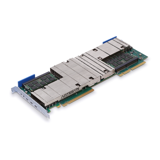
Chapter 1 Introduction This chapter provides a brief overview of SharpStreamer™ Pro Mini PCIE-7210-1card, its features and applications, hardware and software overview, standard compliance, and ordering information. The Artesyn SharpStreamer™ Pro Mini PCIE-7210-1 is a high performance video accelerator card offers High Efficiency Video Coding (HEVC) video transcoding services quickly and dynamically. -
Page 26: Hardware Overview
Introduction Two Micro SD slots, one supporting up to 64 GB for Skylake PCH and the other up to 8 GB for Quark processor. Two serial console interfaces on faceplate for Skylake PCH and Quark processor. 1 GB Ethernet Interface between the Skylake-H CPU and the PEX9716. ... -
Page 27: Figure 1-1 Mechanical Layout-Top View
Introduction Figure 1-1 Figure 1-2 depicts top and bottom views of the PCIE-7210-1 card . Figure 1-1 Mechanical Layout-Top View 167.65 mm 111.15 mm Edge Connector SharpStreamer™ Pro Mini PCIE-7210-1 Installation and Use (6806800U78A) -
Page 28: Software Overview
Introduction Figure 1-2 Bottom View Software Overview The software for the PCIE-7210-1 card is delivered in the form of integrated ISO image which contains CentOS based Linux OS, necessary binaries, utilities, tools to enable PCIE-7210-1 card functionality for media transcoding and firmware upgrades. SharpStreamer™... -
Page 29: Standard Compliances
Introduction Standard Compliances The PCIE-7210-1 card meets the following standards. Table 1-1 Standard Compliances Standard Description 47CFR15 (FCC) Class A ANSI C63.4 Radiated Emissions EN 55032,CISPR 32 Class A ICES-003 Class A 47CFR15 (FCC) ANSI C63.4 Conducted Emissions EN 55032, CISPR 32 Class A ICES-003 Class A EN 300 386 v1.6.1: 2012 EN 61000-4-2: 2009 EN 300 386 v1.6.1: 2012 EN 61000-4-3: 2010... - Page 30 Introduction SharpStreamer™ Pro Mini PCIE-7210-1 Installation and Use (6806800U78A)
-
Page 31: Hardware Preparation And Installation
Chapter 2 Hardware Preparation and Installation This chapter provides information on unpacking and inspecting the card procedures and safety precautions to be followed while handling the card. The environmental, thermal, power requirements, installation, and removal procedures of the card are also explained in this chapter. -
Page 32: Environmental, Thermal, And Power Requirements
Hardware Preparation and Installation 3. Remove the desiccant bag shipped with the card and dispose it according to your country’s legislation. Make sure the card is thoroughly inspected before shipment. If any damage has occurred during transportation please contact our Contact Center immediately. Environmental, Thermal, and Power Requirements The following sections provide the environmental, thermal, and power requirements of the... -
Page 33: Power Requirements
Hardware Preparation and Installation The following table provides the environmental and the thermal requirements for the PCIE- 7210-1 card. Table 2-1 Environmental and Thermal Requirements Requirement Operating Non-Operating Temperature 0°C to 35°C -40°C to 70°C for altitude less than 950 m or 3117 feet Minimum Airflow 600 LFM (3 m/Sec) -
Page 34: Precautions
Hardware Preparation and Installation Precautions To reduce the risk of personal injury, fire, or damage to the equipment, do not overload the AC supply circuit that provides power to the chassis. The card must be powered and connected only to a controlled voltage source. ... -
Page 35: Esd Prevention
Hardware Preparation and Installation 2.3.1 ESD Prevention Static electricity may hurt you or damage the device. To minimize the damage, pay attention to the following points: Before touching the card or electronic components, make sure that you are working in an ... -
Page 36: Pcie-7210-1 Card Installation And Removal
Hardware Preparation and Installation PCIE-7210-1 Card Installation and Removal This section contains the PCIE-7210-1 card installation and removal procedures. Shipping the card along with a server is not recommended. If you still need to ship the card along with the server, ensure the card is properly secured in the server. -
Page 37: Pcie-7210-1 Card Removal
Hardware Preparation and Installation 3. Verify the switch S5 settings as per the host server. See Switch Settings on page 4. Insert the PCIE-7210-1 card into the PCIe slot, secure it, and ensure that the card is properly fitted in the PCIe slot. 5. - Page 38 Hardware Preparation and Installation SharpStreamer™ Pro Mini PCIE-7210-1 Installation and Use (6806800U78A)
-
Page 39: Functional Description
Skylake-H processor with built-in Graphics Processing Unit (GPU) for graphics processing and allow the CPU cores to process other functionality. The following figure depicts the functional block diagram of the PCIE-7210-1 card. Figure 3-1 SharpStreamer Pro Mini PCIE-7210-1 Block Diagram CP2105 POWER Sensor... -
Page 40: Cpu Complex
Functional Description CPU Complex The CPU complex of the PCIE-7210-1 card comprises of an Intel E3-1578L v5 processor and a PCH. 3.1.1 Intel Skylake-H Processor ® ® Skylake-H is an Intel Xeon E3-1585 v5 64 bit multi core processor built on 14 nm process technology. -
Page 41: Power
Functional Description The PEX9716 PCI Express switch supports the following features: 16 lanes with integrated on-chip SerDes Low-power SerDes (less than 90 mW per Lane) Device-Specific Relaxed Ordering Port configuration – Five (5) independent ports – Choice of link width (quantity of lanes) per unique Link/Port -x2, x4, or x8 –... -
Page 42: Low Speed Serial Interface
Functional Description – x1 PCIe lane connected between the Skylake-H PCH and I219 PHY device. – x1 PCIe lane connected between PEX9716 switch and I210 Ethernet Controller. – x1 PCIe lane connected between PEX9716 switch and the Intel Quark SoC device. Each lane operates at Gen 2 (5 GT/s). -
Page 43: Serial Voltage Identification
Functional Description System Management Bus (SMBus) is used as interface between devices. Inter Integrated Circuit The I2C0 interface is connected to the inlet and outlet onboard temperature sensors. 3.6.2.2 Serial Voltage Identification The Serial Voltage Identification (SVID) is a three-wire digital interface used to transfer power management information between the master and the slave. -
Page 44: Micro Sd As Boot Device
Functional Description The following figure shows the location of the Micro SD slots on the PCIE-7210-1 card. Figure 3-2 Micro SD Slot Location Skylake PCH - microSD slot Quark processor - microSD slot 3.7.1 Micro SD as Boot Device By default, during the card boot operation, the BIOS will first look for a boot record on the Micro SD storage device. -
Page 45: Clock Distribution
Functional Description Figure 3-3 shows the location of the temperature and the power sensors on the card. Figure 3-3 Location of Temperature and power sensors - Secondary Side Power sensor Temperature sensor Clock Distribution Clocking for CPU complex consists of two input crystals. One 24 MHz crystal to drive all the main buses and a 32.768 KHz crystal to drive the Real Time Clock (RTC). -
Page 46: 3.10 Reset Management
Functional Description 3.10 Reset Management PEX9716 switch and PCH resets are controlled by the CPLD. CPU and Peripheral reset are controlled by PCH. During power up the CPLD state machine drives the reset control to CPU during an induced reset from the front panel reset switch. For more information about Reset button, refer the section Controls on page 3.11 JTAG... -
Page 47: Controls, Indicators, And Connectors
Chapter 4 Controls, Indicators, and Connectors This chapter provides information on controls, indicators, and connectors associated with the PCIE-7210-1 card. Connectors 4.1.1 PCIE-7210-1 Faceplate View The following figure shows the faceplate view of the PCIE-7210-1 card. Figure 4-1 PCIE-7210-1 Faceplate Push Button Reset Console... -
Page 48: Edge Connector
Controls, Indicators, and Connectors The PCIE-7210-1 card comes with a gold finger edge connector. 4.1.2 Edge Connector This section provides information about the PCIE-7210-1 card edge connector pinout. Table 4-1 PCIE-7210-1 Card Edge Connector Pinout Pin # Name Side B Description Name Side A Description +12V-CONN... - Page 49 Controls, Indicators, and Connectors Table 4-1 PCIE-7210-1 Card Edge Connector Pinout (continued) Pin # Name Side B Description Name Side A Description Ground PCIE_G3_R Receiver Lane 0, Differential X0_P_N pair RSVD Reserved Ground Ground PCIE_G3_TX1_ Transmitter Lane 1, RSVD Reserved Differential pair Ground Ground...
-
Page 50: Cpld Programmer Jtag Port
Controls, Indicators, and Connectors Table 4-1 PCIE-7210-1 Card Edge Connector Pinout (continued) Pin # Name Side B Description Name Side A Description Ground RSVD Reserved Ground RSVD Reserved RSVD Reserved Ground RSVD Reserved Ground Ground RSVD Reserved PCIE_EDGE_PR Hot-Plug presence RSVD Reserved ESENT_X8... -
Page 51: Atx Power Connector
Controls, Indicators, and Connectors 4.1.4 ATX Power Connector The 12 V ATX power connector is optionally provided on board. Table 4-3 ATX Power Connector Pinout Name +12V0_ATX +12V0_ATX +12V0_ATX Ground Ground Ground SharpStreamer™ Pro Mini PCIE-7210-1 Installation and Use (6806800U78A) -
Page 52: Leds
Controls, Indicators, and Connectors LEDs 4.2.1 Debug LEDs The following figure depicts location of debug LEDs (D17, D16, D15, D14, D13, D12, D11, and D10) on the PCIE-7210-1 card. Figure 4-2 Location of Debug LEDs Debug LEDs Table 4-4 PEX9716 Power Status Representation Value Status... -
Page 53: Table
Controls, Indicators, and Connectors Table 4-5 SoC Power Status Value Representation Status SoC power is up & stable LED will glow. SoC power is not up LED will not glow. Table 4-6 PCH Sleep Status Representation Value Status PCH is out of sleep status LED will glow. -
Page 54: Port Good Leds
Controls, Indicators, and Connectors 4.2.2 Port Good LEDs Four (4) Port Good LEDs are connected to PEX9716 device indicating the status of all ports connected to PEX9716. The following figure depicts location of Port Good LEDs (D28, D29, D30, and D31) on the PCIE-7210-1 card. Figure 4-3 Location of Port Good LEDs Port Good LEDs... -
Page 55: I210 Leds
Controls, Indicators, and Connectors The following table indicates On/Off state of a Port Good LED. Table 4-10 On/Off state of a Port Good LED State LED Pattern Link is down Link is Up, 2.5 GT/s, any negotiated Link width Blinking, 512 ms On, 512 ms Off (1 Hz) Link is Up, 5.0 GT/s, any negotiated Link width Blinking, 256 ms On, 256 ms Off (1 Hz) Link is Up, 8.0 GT/s, any negotiated Link width... -
Page 56: I219 Leds
Controls, Indicators, and Connectors Table 4-11 I210 LEDs Status Indication Indicates the Link up activity of I210 device. Indicates the 1000 Mbps Link activity of I210 device. Indicates the 100 Mbps Link activity of I210 device. 4.2.4 I219 LEDs The following figure depicts location of I219 LEDs (D34, D35, and D36). Figure 4-5 Location I219 LEDs i219 LEDs... -
Page 57: User Led
Controls, Indicators, and Connectors Table 4-12 I219 LEDs Status Indication Indicates the Link up activity of I219 device. Indicates the 1000 Mbps Link activity of I219 device. Indicates the 100 Mbps Link activity of I219 device. 4.2.5 User LED The PCIE-7210-1 card contains a user LED (D21), displayed on the front panel. It is a tricolor LED which indicates Red, Green, and Blue colors. -
Page 58: User Led Status
Controls, Indicators, and Connectors Table 4-13 User LED Color Indication Color Indication Green Indicates power up of Skylake and PCH Indicates power failure of Skylake and PCH Blue Indicates the PEX mode Blinking Blue LED indicates Base Mode Solid Blue LED indicates Fabric Mode ... -
Page 59: Controls
Controls, Indicators, and Connectors Controls The Reset button S3 is located on the faceplate of the PCIE-7210-1 card. By pressing this button, CPU on the card gets reset. Figure 4-7 S3 Reset Button SharpStreamer™ Pro Mini PCIE-7210-1 Installation and Use (6806800U78A) -
Page 60: Switch Settings
Controls, Indicators, and Connectors Switch Settings The following figure depicts location of switches on the PCIE-7210-1 card. Figure 4-8 Location of Switches Table 4-15 Switch Position Indication based on Host Server MaxCore MaxCore Switch MC3000 MC1000 IPC MaxCore PICO Switch S5 Pin 1 Down (PEX9716 Up (PEX9716 in Down (PEX9716 in... -
Page 61: Figure 4-9 Switch Settings- Maxcore Mc3000 And Maxcore Mc1000 Ipc
Controls, Indicators, and Connectors Table 4-15 Switch Position Indication based on Host Server (continued) MaxCore MaxCore Switch MC3000 MC1000 IPC MaxCore PICO Switch S5 Pin 3 Down (PEX9716 Up (PEX9716 Ref. Down (PEX9716 Up (PEX9716 Ref. Ref. Clock from Clock from Ref. -
Page 62: Figure 4-11 Switch Settings Rms
Controls, Indicators, and Connectors Figure 4-10 MaxCore PICO Figure 4-11 Switch Settings RMS SharpStreamer™ Pro Mini PCIE-7210-1 Installation and Use (6806800U78A) -
Page 63: Pcie Software
Chapter 5 PCIE Software This chapter provides information on software components used on PCIE-7210-1, modes of operation, prerequisites for card operation, power up and power down timing sequence, software installation, network configuration, software installation tools, and firmware upgrade. Software Components The PCIE-7210-1 consists of three subsystems (Quark, Skylake-H and Host) called as integrated system. -
Page 64: Base Mode
PCIE Software 5.2.1 Base Mode If the PCIE-7210-1 is used in MaxCore MC3000 environment, PEX9716 should be programmed with Base Mode configuration. In this mode, PEX9716 acts as a simple PCIe switch connected to Skylake-H. Skylake-H will act as the root complex and Quark subsystem will not be used in base mode. -
Page 65: Console Settings
PCIE Software For Quark and Skylake-H, the configuration is already set. For host server, ensure that the SSC clock is set as per table below. HOST Spread Spectrum Clock Setting Quark Disabled Skylake-H Disabled Host Enabled 5.3.2 Console Settings For console settings of Quark and Skylake-H processor, following are the recommended settings to be configured for minicom/teraterm. -
Page 66: Power Sequence
PCIE Software 5.3.3 Power Sequence The following subsections provide guidelines for power up and power down sequence of various subsystems in RMS/MaxCore MC1000 IPC. In MaxCore MC3000 server the power up sequence would be taken care of by the server power sequencing. -
Page 67: Table 5-3 Power Up Timing Sequence
PCIE Software 5.3.3.1.1 Timing Sequence This section provides in brief the PCIE-7210-1 card power up sequence in relative to the time the card is plugged into the server and power provided to the server. The below times are not absolute times and are relative with respect to the time the server is powered on. Table 5-3 Power Up Timing Sequence SKYLAKE-H QUARK... -
Page 68: Power Down Sequence
PCIE Software 5.3.3.1.2 T1 - Host Server Resets in BIOS The PCIE-7210-1 card is qualified on third party RMS like Dell R730 and Dell R430 with CentOS 7.X. These servers will throw an error in BIOS and would continuously reset till the card is configured. -
Page 69: Software Deliverables
PCIE Software Software Deliverables Software deliverables provided are based on CentOS 7.X Linux distribution. The card software consists of three components and need to be installed for proper functioning. The default runlevel for Quark and Skylake-H OSes are set to runlevel 3. The root file system does not contain any graphical interface packages. -
Page 70: Quark Management Cpu
PCIE Software 8. Refer to Artesyn specific tools, that can be used on host server in configuration and usage: pcie7210-1-tool.sh. 9. Follow the power down sequence detailed inPower Down Sequence. 5.4.2 Quark Management CPU Quark will be used as mCPU only when PEX9716 is configured in fabric mode. Quark OS distribution is based on YOCTO distribution running with Kernel 4.3.3. - Page 71 PCIE Software Example: /mnt/utils/create_bootusb.sh 4. Once the installation is completed, a message is displayed accordingly. 5. Connect the Micro SD card/ USB Quark. Connect to Quark serial console on the faceplate with a Baud rate of 115200. Flow control should be XON/XOFF. 6.
-
Page 72: Login Details
PCIE Software If Installed BIOS is less than 3.0.7, the baud rate would be 115200 and the OS if earlier than GA version, the default baud rate would be 115200. Based on the BIOS and OS versions installed on the board, customers are requested to set the baud rate accordingly. -
Page 73: Creating A Bootable Usb On A Linux Machine
PCIE Software 5.4.3.2 Creating a Bootable USB on a Linux Machine Pre-requisites: 1 GB USB drive. A PC with CentOS 7.X with following utilities are installed. The installation script would verify the presence of these utilities and will exist if the utilities are not available. –... - Page 74 PCIE Software Disk for installation. – USB drive or Micro SD card. – NOTE: the disk for installation should have atleast 64 GB of space. Installable files [available on ISO/bootable USB drive in /images directory]: – filesh.sha1sum – vmlinuz –...
-
Page 75: Login Details
PCIE Software Example: $ flashrfsrc.sh -d disk:sda -i local:/root/images 5.4.3.3.1 Automatic Installation Local Disk If the installation is onto a local disk with following information Disk: sda Images location: /media/usbdrive/images Command usage $ opt/board/tools/flashrfsrc.sh –d disk:sda –I local:/media/usbdrive/images 5.4.3.3.2 Manual Installation Manual installation needs the card to be booted using PXE boot. -
Page 76: Rack Mount Server
PCIE Software 5.4.4 Rack Mount Server Install OS which is compatible to the following rpm. Supported OS version and Kernel version are part of the rpm name. Table 5-6 rpm Information RPM Name Description RPM Contains sspromini-pcieutils- <os_version-kernel_version- PLX vNIC Kernel driver ... -
Page 77: Network Configuration
PCIE Software Network Configuration For each card, Skylake-H and Host CPU are assigned with vNIC each. vNIC on Skylake-H will try to fetch the IP via DHCP server running on the Host CPU. On RMS, a DHCP server will be listening on each of its vNIC interfaces. -
Page 78: Usage
PCIE Software ifconfig pexnic2 hw ether 00:0e:0f:00:05:12 ifconfig pexnic3 hw ether 00:0e:0f:00:05:13 5.6.2 Usage [root@dell-server ~]# /opt/bladeservices/tools/pcie7210-1-tool.sh Available options are as below Provides information about each card's --list-slots physical slots, local IP and Skylake IP Writes dhcp and network configuration --write-dhcp-conf of I210 and plxcnic for each card to service requests from Skylake... -
Page 79: Skylake-H
PCIE Software 3. CONNECTED-NIC shows the card’s network interfaces that are provided to RMS. Each card provides two devices to RMS i.e. I210 (pxpx) and plxcnicx, which are connected to Skylake’s I219 and plxcnic0 respectively. 4. CONNECT-IP is the IP address that will be assigned to the CONNECTED-NIC locally. 5. - Page 80 PCIE Software SharpStreamer™ Pro Mini PCIE-7210-1 Installation and Use (6806800U78A)
-
Page 81: Firmware Upgrade
Chapter 6 Firmware Upgrade This chapter provides information on BIOS and CPLD firmware upgrades. The PCIE-7210-1 card has two firmware components that can be upgraded. Skylake-H BIOS CPLD The BIOS and CPLD images can be upgraded using the Firmware Command line Utility (FCU) provided with the OS image of Skylake-H CPU. - Page 82 Firmware Upgrade For upgrading the BIOS, execute the following command. /opt/bladeservices/rom/7210-1/bios/ Once the above command is executed, if the result is success, a new BIOS firmware image gets copied to temporary flash location. This should be followed by a reboot operation. After reboot, once the BIOS starts executing, it will program the BIOS image from temporary flash location to the BIOS bank.
-
Page 83: Cpld Firmware Upgrade
Firmware Upgrade Do not power off or reset the system while above operation is in progress. Doing so, corrupts the BIOS flash and the board never comes up. Once the upgrade operation is successful, the card will go for automatic reset and boots with the upgraded BIOS. CPLD Firmware Upgrade FCU utility can also be used for upgrading the CPLD firmware. - Page 84 Firmware Upgrade #01 Device : pcie7210-1-cpu Bank #0 - Active Version: 2.0.00000000 ********************[[[[[ REPORT END ]]]]]******************** For upgrading the CPLD firmware, execute the command as follows: fcu -uf <filename>.fri Once the above command is executed, if the result is success, means the CPLD firmware is upgraded.
-
Page 85: Programming
Appendix A Programming This appendix describes programming PEX9716 eeprom. Programming PEX9716 eeprom with Base Mode using PlxCm on Quark A.1.1 Pre-requisites Install OS on Quark SD card. See Offline Micro SD Card Installation and Booting. Dell server. Fabric mode hardware switch settings.See Fabric Mode. - Page 86 Programming 4. Run /opt/board/tools/PlxCm 5. eep_load ./9716_base.bin Output similar to below could be observed. =============================================== Load EEPROM file..Ok (32B) Verify option.....ENABLED (Use '/b' to disable) Program EEPROM....00% Calculate & update CRC..Ok (CRC=89CB8E36) -- Complete (0.03 sec) -- SharpStreamer™ Pro Mini PCIE-7210-1 Installation and Use (6806800U78A)
-
Page 87: Programming Pex9716 Eeprom With Fabric Mode Using Plxcm On Skylake
Programming Programming PEX9716 eeprom with Fabric Mode using PlxCm on Skylake A.2.1 Pre-requisites Bootable pendrive or SD card OS. See Skylake-H. MaxCore. Base Mode hardware switch settings. See Base Mode. A.2.2 Instructions 1. Place the card in MaxCore Chassis and power on the card. 2. - Page 88 Programming 4. Run /opt/bladeservices/bin/PlxCm 5. eep_load 9716_fabric.bin Output similar to below could be observed. =============================================== Load EEPROM file..Ok (50B) Verify option.....ENABLED (Use '/b' to disable) Program EEPROM....Ok Calculate & update CRC..Ok (CRC=ADDA267E) -- Complete (0.03 sec) -- SharpStreamer™ Pro Mini PCIE-7210-1 Installation and Use (6806800U78A)
-
Page 89: Programming Pex9716 With Aardvark I2C From Windows
Programming Programming PEX9716 with Aardvark I2C from Windows This option is not supported by default and may need to mount a header on the board. For programming, refer to A.1 on page 85 A.2 on page A.3.1 Pre-requisites The PCIE-7210-1 with I2C header from PEX9716. ... - Page 90 Programming mmr 264 0000005A d. mmr 260 00A3C000 e. mmr 260 00A3C000 6. Power cycle the card by power cycling Dell server 7. Once the device appears in PEX editor, program the device with the EEPROM. 8. Power cycle the card by power cyling Dell server. 9.
-
Page 91: Table B-1 Artesyn Embedded Technologies - Embedded Computing Publications
3. In the Search text box, type product or manual name and click Filter. Table B-1 Artesyn Embedded Technologies - Embedded Computing Publications Document Title Publication Number SharpStreamer Pro Mini PCIE-7210-1 Quick Start Guide 6806800U92 SharpStreamer Pro Mini PCIE-7210-1 Safety Notes 6806800U93... - Page 92 Related Documentation SharpStreamer™ Pro Mini PCIE-7210-1 Installation and Use (6806800U78A)
- Page 94 Artesyn Embedded Technologies, Artesyn and the Artesyn Embedded Technologies logo are trademarks and service marks of Artesyn Embedded Technologies, Inc. All other product or service names are the property of their respective owners. © 2017 Artesyn Embedded Technologies, Inc.
Need help?
Do you have a question about the SharpStreamer Pro Mini PCIE-7210-1 and is the answer not in the manual?
Questions and answers