Table of Contents
Advertisement
Quick Links
UM2708
User manual
Discovery kit for IoT node, multi-channel communication with STM32L4+ Series
Introduction
The
B-L4S5I-IOT01A
Discovery kit for the IoT node allows the user to develop applications with a direct connection to the cloud
servers.
The B-L4S5I-IOT01A Discovery kit for the IoT node enables a wide diversity of applications by exploiting low-power
®
®
multilink communication (Bluetooth
Low Energy, Wi‑Fi
, NFC), multiway sensing (detection, environmental awareness) and
®
®
Arm
Cortex
-M4 core-based STM32L4+ Series features.
®
™
ARDUINO
Uno V3 and Pmod
connectivity provide unlimited expansion capabilities with a large choice of specialized add-on
boards.
The B-L4S5I-IOT01A Discovery kit for the IoT node includes an ST-LINK debugger/programmer and comes with the
comprehensive STM32CubeL4 MCU Package, which provides an STM32 comprehensive software HAL library as well as
various software examples to seamlessly connect to cloud servers.
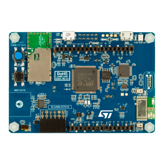
Figure 1.
B-L4S5I-IOT01A Discovery kit for the IoT node
Picture is not contractual.
UM2708 - Rev 2 - December 2021
www.st.com
For further information contact your local STMicroelectronics sales office.
Advertisement
Table of Contents

Subscribe to Our Youtube Channel
Related Manuals for ST UM2708


Summary of Contents for ST UM2708
- Page 1 The B-L4S5I-IOT01A Discovery kit for the IoT node includes an ST-LINK debugger/programmer and comes with the comprehensive STM32CubeL4 MCU Package, which provides an STM32 comprehensive software HAL library as well as various software examples to seamlessly connect to cloud servers.
-
Page 2: Features
Flexible power-supply options: ST-LINK USB V , USB connector, or external sources • On-board ST-LINK/V2-1 debugger/programmer with USB re-enumeration capability: mass storage, Virtual COM port, and debug port • Comprehensive free software libraries and examples available with the STM32Cube MCU Package •... -
Page 3: Ordering Information
MCU product line in STM32 32-bit Arm Cortex MCUs STM32L4R5/S5 in the STM32L4+ Series STM32 Flash memory size: 2 Mbytes • I for 2 Mbytes Dedicated to IoT applications Discovery kit for IoT applications UM2708 - Rev 2 page 3/41... -
Page 4: Development Environment
STM32 Flash memory for easy demonstration of the device peripherals in standalone mode. The latest versions of the demonstration source code and associated documentation can be downloaded from www.st.com. UM2708 - Rev 2 page 4/41... -
Page 5: Conventions
Jumper fitted between Pin 1 and Pin 2 Solder bridge SBx ON SBx connections closed by 0 Ω resistor Solder bridge SBx OFF SBx connections left open Resistor Rx ON Resistor soldered Resistor Rx OFF Resistor not soldered UM2708 - Rev 2 page 5/41... -
Page 6: Delivery Recommendations
Before first use, check the board for any damage that might have occurred during shipment, that all socketed components are firmly fixed in their sockets and that none are loose in the plastic bag. UM2708 - Rev 2 page 6/41... -
Page 7: Hardware Layout And Configuration
2) illustrates the ® ™ connection between the STM32 and peripherals: embedded ST-LINK, ARDUINO Uno V3 shields, Pmod connector, Quad-SPI Flash memory, USB OTG connectors, digital microphones, various ST-MEMS sensors, ® ® and the three RF modules (Wi‑Fi , Bluetooth , and NFC). -
Page 8: Figure 3. B-L4S5I-Iot01A Discovery Kit For The Iot Node Layout (Top View)
Figure 3. B-L4S5I-IOT01A Discovery kit for the IoT node layout (top view) -
Page 9: Figure 4. B-L4S5I-Iot01A Discovery Kit For The Iot Node Layout (Bottom View)
Figure 4. B-L4S5I-IOT01A Discovery kit for the IoT node layout (bottom view) -
Page 10: Figure 5. B-L4S5I-Iot01A Discovery Kit For The Iot Node Mechanical Drawing In Millimeters
Figure 5. B-L4S5I-IOT01A Discovery kit for the IoT node mechanical drawing in millimeters... -
Page 11: Embedded Stlink/V2-1
6.1.2 ST-LINK/V2-1 firmware upgrade The ST-LINK/V2-1 embeds a firmware upgrade mechanism for the in-situ upgrade through the USB port. As the firmware may evolve during the lifetime of the ST-LINK/V2-1 product (for example new functionalities, bug fixes, support for new microcontroller families), it is recommended to visit the www.st.com... -
Page 12: Power Supply
Figure This is a 5V DC power with limitation from CN7, the USB type Micro-B connector of ST-LINK/V2-1. In this case, the JP4 jumper must be fitted between pin 1 and pin 2 to select the 5V_ST_LINK power source on the JP4 silkscreen. -
Page 13: Figure 8. Jp4: 5V_Ard Selection From Cn6 (Vin)
This is the DC power coming from an external source. In this case, the JP4 jumper must be fitted between pin 7 and pin 8 to select the 5V_VBAT power source on JP4 silkscreen. UM2708 - Rev 2 page 13/41... -
Page 14: Figure 10. Jp4: 5V_Vbat
In this specific case only, the resistor R30 must be soldered, to allow the board to be powered anyway. Caution: Do not connect the PC to the ST-LINK (CN7) when R30 is soldered. The PC may be damaged or the board may not be powered correctly. UM2708 - Rev 2... - Page 15 3D gyroscope LPS22HB digital barometer HTS221 humidity and temperature VL53L0X ToF and gesture detection STSAFE-A110 authentication and security (I)MP34DT0x digital microphone (I)MP34DT0x digital microphone VDD_MCU MCU STM32L4S5VIT6 VDDA IC12 3V3_Wifi ISM43362-M3G-L44 LT1963EST-3.3 Wi-Fi ® module UM2708 - Rev 2 page 15/41...
-
Page 16: Programming And Debugging When The Power Supply Is Not From St-Link (5V_St_Link)
UM2708 Programming and debugging when the power supply is not from ST-LINK (5V_ST_LINK) Programming and debugging when the power supply is not from ST-LINK (5V_ST_LINK) It is mandatory to power the board first using CN2 (VIN) or CN9 (USB_FS_OTG), then to connect the USB cable to the PC. -
Page 17: Virtual Com Port
Virtual COM port The serial interface USART1 is directly available as a Virtual COM port of the PC connected to the ST-LINK/V2-1 USB connector CN7. The Virtual COM port settings are configured with 115200 bps, 8-bit data, no parity, one-stop bit, and no flow control. -
Page 18: Inventek Systems Ism43362-M3G-L44 (802.11 B/G/N Compliant Wi-Fi ® Module)
128 blocks of 4 bytes which can be split into four flexible and protectable areas. Note: The hardware layout is ready to support a Sub-GHz low-power-programmable RF module (SPSGRF-868 or SPSGRF-915). The footprint is implemented (M3 designation), but no module is soldered. UM2708 - Rev 2 page 18/41... -
Page 19: Stmicroelectronics Sensors
• Or IMP34DT05 on MB1297-L4S5VI-E03 revision (BL4S5IIO01A$CU3). These microphones are ultra-compact, low-power, omnidirectional, digital ST-MEMS microphones built with a capacitive sensing element and an IC interface. On the B-L4S5I-IOT01A Discovery kit for the IoT node, there are two (I)MP34DT0x microphones: one with LR pulled to VDD and the second with LR pulled low. -
Page 20: Time-Of-Flight And Gesture Detection Sensor (Vl53L0X)
Two green LEDs (LD1 and LD2), located on the top middle side are available for the user. To light a LED a high logic state HIGH must be written in the corresponding GPIO. Table 2 gives the assignment of the control ports to the LED indicators. UM2708 - Rev 2 page 20/41... -
Page 21: I 2 C Addresses Of Modules Used On Mb1297
0101001x 0x52 0x53 detection sensor 0xAE for system 0xAF for system area area ST25DV04K Dynamic NFC/RFID TAG IC 1010x11x 0xA6 for user 0xA7 for user memory memory STSAFE-A110 Highly secure solution 0100000x 0x40 0x41 UM2708 - Rev 2 page 21/41... -
Page 22: Connectors
B-L4S5I-IOT01A Discovery kit for the IoT node. Example connector references (Refer to Figure 17): • CN4: Header 6X1_Female_SMD • CN3: Header 8X1_Female_SMD • CN2: Header 8X1_Female_SMD • CN1: Header 10X1_Female_SMD ® Figure 17. ARDUINO Uno V3 connectors UM2708 - Rev 2 page 22/41... -
Page 23: Table 6. Arduino ® Connector Pinout
PWM / D6 ARD.D6-PWM TIM3_CH4 PWM / D5 ARD.D5-PWM TIM3_CH1 ARD.D4 TIMxx PWM / D3 ARD.D3-PWM / INT1_EXTI0 TIM3_CH3 / EXTI0 ARD.D2-INT0_EXTI14 PD14 EXTI14 TX / D1 ARD.D1-UART4_TX UART4_TX RX / D0 ARD.D0-UART4_RX UART4_RX UM2708 - Rev 2 page 23/41... -
Page 24: Cn5 Tag Connector
The TAG connector is implemented on the B-L4S5I-IOT01A Discovery kit for the IoT node. The TAG connector is a 10-pin footprint supporting SWD mode, which is shared with the same signals as the ST-LINK. The TC2050- IDC-NL cable is used to link ST-LINK and TAG connector on the B-L4S5I-IOT01A Discovery kit for the IoT node so that the STM32L4+ can be easily programmed and debugged without any extra accessory. -
Page 25: St-Link/V2-1 Usb Micro-B
UM2708 ST-LINK/V2-1 USB Micro-B ST-LINK/V2-1 USB Micro-B The USB connector is used to connect the embedded ST-LINK/V2-1 to the PC to program and debug the STM32L4S5VIT6 microcontroller. Table 8. USB Micro-B connector pinout STM32L Connector Pin name Signal name Function... -
Page 26: Pmod™ Connector Cn10
2A and 4A. The related STM32L475VG I/Os for the Pmod function are listed in Table ™ The Pmod connector is 2x6-pin with a 2.54 mm pitch and right angle female connector. UM2708 - Rev 2 page 26/41... -
Page 27: Table 12. Pmod ™ Solder Bridge Configuration
™ Table 12. Pmod solder bridge configuration Alternate configuration (UART) Standard configuration (SPI) STM32L Solder bridge STM32L Solder bridge Pin name Pin name ™ Pin name STM32L4+ pin Pmod pin number 4+ pin configuration 4+ pin configuration PMOD- SB14 OFF SB14 OFF PMOD-UART2_Tx / UART2_CTS /... -
Page 28: Jumper Jp5 For Idd Measurements
The STM32 current measurement can be done on JP5. By default, a jumper is placed on JP5. For the current measurement configuration, the jumper on JP5 must be removed and an amp-meter must be placed on JP5. UM2708 - Rev 2 page 28/41... -
Page 29: B-L4S5I-Iot01A Discovery Kit For The Iot Node Information
Evaluation tools marked as “ES” or “E” are not yet qualified and therefore not ready to be used as reference design or in production. Any consequences deriving from such usage will not be at ST charge. In no event, ST will be liable for any customer usage of these engineering sample tools as reference designs or in production. -
Page 30: Board Mb1297 Revision E03
No limitation identified for this board revision. 8.3.2 Board MB1297 revision E03 ® The revision E03 is the first official release of the MB1297 board with a BlueNRG-M0 Bluetooth module. Board limitations No limitation identified for this board revision. UM2708 - Rev 2 page 30/41... -
Page 31: Appendix A B-L4S5I-Iot01A Discovery Kit For The Iot Node I/O Assignment
ARD.D1-UART4_TX UART4-RX ARD.D0-UART4_RX TIM2_CH3 ARD.D10-SPI_SSN/PWM GPIO_Output ARD.D4 3.3 V DD_MCU GPIO_Output ARD.D7 SPI1_SCK ARD.D13-SPI1_SCK / LED1 SPI1_MISO ARD.D12-SPI1_MISO SPI1_MOSI ARD.D11-SPI1_MOSI / PWM ADC1_IN13 ARD.A1-ADC ADC1_IN14 ARD.A0-ADC TIM3_CH3 ARD.D3-PWM / INT1_EXTI0 TIM3_CH4 ARD.D6-PWM GPIO_Output ARD.D8 UM2708 - Rev 2 page 31/41... - Page 32 ) & LED4 (BLE) GPIO_Output SPBTLE-RF-RST USB_OTG USB_OTG_FS_VBUS PA10 USB_OTG USB_OTG_FS_ID PA11 USB_OTG USB_OTG_FS_DM PA12 USB_OTG USB_OTG_FS_DP PA13 ST-LINK SYS_JTMS-SWDIO 3.3 V DDUSB DD_MCU 3.3 V DD_MCU PA14 ST-LINK SYS_JTCK-SWCLK PA15 TIM2_CH1 ARD.D9-PWM PC10 SPI3_CLK INTERNAL-SPI3_SCK UM2708 - Rev 2 page 32/41...
- Page 33 USART2_CTS PMOD-UART2_CTS/SPI2_MISO USART2_RTS PMOD-UART2_RTS/SPI2_MOSI USART2_TX PMOD-UART2_TX/SPI2_CSN USART2_RX PMOD-UART2_RX GPIO_Output STSAFE-A110-RESET ST-LINK SYS_JTDO-SWO TIM3_CH1 ARD.D5-PWM GPIO_Output SPSGRF-915-SPI3_CSN USART1_TX ST-LINK-UART1_TX USART1_RX ST-LINK-UART1_RX BOOT0 Boot BOOT0 I2C1_SCL ARD.D15-I2C1_SCL I2C1_SDA ARD.D14-I2C1_SDA GPIO_Output ISM43362-SPI3_CSN GPIO_EXTI1 ISM43362-DRDY_EXTI1 3.3 V DD_MCU UM2708 - Rev 2 page 33/41...
-
Page 34: Appendix B Federal Communications Commission (Fcc) And Innovation, Science And Economic Development Canada (Ised) Compliance Statements
Americas Region Legal | Group Vice President and Regional Legal Counsel, The Americas STMicroelectronics, Inc. 750 Canyon Drive | Suite 300 | Coppell, Texas 75019 Telephone: +1 972-466-7845 ISED Compliance Statement ISED Compliance Statement MB1297-L4S5VI-E02 revision (BL4S5IIO01A$CU2): • Contains/Contient IC: 10147A-362 • Contains/Contient IC: 8976C-SPBTLERF UM2708 - Rev 2 page 34/41... -
Page 35: Red Compliance Statement
Directive 2014/53/EU. The full text of the EU declaration of conformity is available at the following internet address: www.st.com/en/product/b-l4s5i-iot01A. Frequency range used in transmission and maximal radiated power in this range: ® ® • Frequency range: 2400-2483.5 MHz (Bluetooth , Wi‑Fi • Maximal power: 100 mW e.i.r.p UM2708 - Rev 2 page 35/41... -
Page 36: Revision History
Section B.1 FCC Compliance Statement 2-Dec-2021 • Section B.2 ISED Compliance Statement Added: • Figure 14. BlueNRG-M0 module • Section 8 B-L4S5I-IOT01A Discovery kit for the IoT node information • Section B.3 RED Compliance Statement UM2708 - Rev 2 page 36/41... -
Page 37: Table Of Contents
STMicroelectronics sensors........... . . 19 6.10.1 Two on-board ST-MEMS microphones ((I)MP34DT0x) ......19 6.10.2 Capacitive digital sensor for relative humidity and temperature (HTS221). - Page 38 ST-LINK debug connector CN8 ........
-
Page 39: List Of Tables
ST-LINK debug connector pinout ........ -
Page 40: List Of Figures
TC2050-IDC-NL cable ............. . 24 UM2708 - Rev 2... - Page 41 ST’s terms and conditions of sale in place at the time of order acknowledgement. Purchasers are solely responsible for the choice, selection, and use of ST products and ST assumes no liability for application assistance or the design of Purchasers’...
Need help?
Do you have a question about the UM2708 and is the answer not in the manual?
Questions and answers