Table of Contents
Advertisement
Quick Links
Introduction
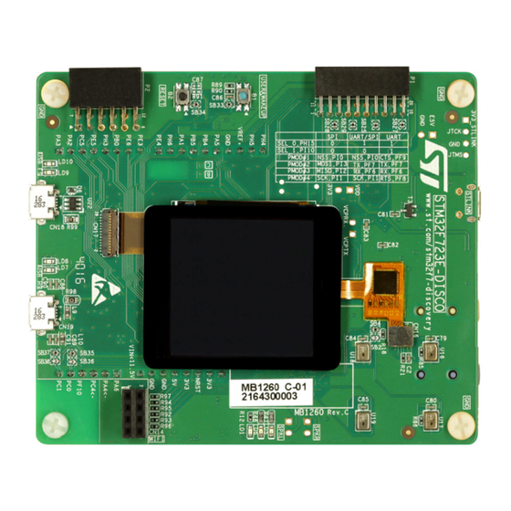
With the STM32F723 Discovery kit (32F723EDISCOVERY), users develop applications
easily on the STM32F7 Series high-performance microcontrollers based on Arm
®
Cortex
-M7 core. The Discovery kit combines the STM32F723 features with 240x240 pixel
LCD with touch panel, SAI audio codec, MEMS microphones, USBs OTG HS and OTG FS,
Quad-SPI NOR Flash memory, and
An embedded ST-LINK/V2-1 debugger/programmer is included. Specialized add-on boards
can be connected through the ARDUINO
connectors.
Figure 1. 32F723EDISCOVERY (Top view)
Pictures are not contractual.
December 2021
Discovery kit with STM32F723IE MCU
microSD™
card connector.
®
Uno V3, Pmod
Figure 2. 32F723EDISCOVERY (Bottom view)
UM2140 Rev 3
UM2140
User manual
™
, or STMod+ expansion
®
1/48
www.st.com
1
Advertisement
Table of Contents

Related Manuals for ST UM2140


Summary of Contents for ST UM2140
-
Page 1: Figure 1. 32F723Ediscovery (Top View)
LCD with touch panel, SAI audio codec, MEMS microphones, USBs OTG HS and OTG FS, Quad-SPI NOR Flash memory, and microSD™ card connector. An embedded ST-LINK/V2-1 debugger/programmer is included. Specialized add-on boards ® ™ can be connected through the ARDUINO... -
Page 2: Table Of Contents
Embedded ST-LINK/V2-1 ........14... - Page 3 Control Touch Panel (CTP) connector ......30 CN1 ST-LINK/V2-1 USB Micro-B connector ..... . 31 6.10...
- Page 4 Revision history ........... . 47 4/48 UM2140 Rev 3...
- Page 5 Document revision history ..........47 UM2140 Rev 3...
- Page 6 CN8 ST-LINK connector ........
-
Page 7: Features
Comprehensive free software libraries and examples available with the STM32Cube MCU Package • On-board ST-LINK/V2-1 debugger/programmer with USB re-enumeration capability: mass storage, Virtual COM port, and debug port • Support of a wide choice of Integrated Development Environments (IDEs) including ®... -
Page 8: Codification
STM32F7XXY-DISCO Description STM32F723E-DISCO MCU series in STM32F7 SRM32F7 Series STM32 32-bit Arm Cortex MCUs MCU product line in the series STM32F723 STM32 Flash memory size: 512 Kbytes E for 512 Kbytes DISCO Discovery kit Discovery kit 8/48 UM2140 Rev 3... -
Page 9: Development Environment
Linux is a registered trademark of Linus Torvalds. c. macOS is a trademark of Apple Inc. registered in the U.S. and other countries. d. All other trademarks are the property of their respective owners. ® e. On Windows only. UM2140 Rev 3 9/48... -
Page 10: Hardware Layout And Configuration
® LCD connector, USB OTG HS and FS connectors, USART, Audio, ARDUINO Uno V3, ™ Pmod and STMod+ shields, and embedded ST-LINK). Figure 4 Figure 5 help users to locate these features on the 32F723EDISCOVERY board. The mechanical dimensions of... -
Page 11: 32F723Ediscovery Discovery Kit Layout
USB OTG FS USB OTG FS USB OTG FS USB OTG HS USB OTG HS USB OTG HS overcurrent LED Micro-AB connector overcurrent LED Micro-AB connector (LD10) (LD9) (CN18) (LD8) (LD7) (CN19) USB OTG FS USB OTG HS UM2140 Rev 3 11/48... -
Page 12: Figure 5. 32F723Ediscovery Bottom Layout
(U2) Audio codec (U7) TAG debug connector Stereo speaker (CN9) outputs (CN10 and CN7) STM32F723IEK6 (U8) 5 V power 8-Mbit selection PSRAM connector Memory (CN8) (U10) ® ARDUINO Uno V3 connector (CN11, CN12, CN13, and CN15) 12/48 UM2140 Rev 3... -
Page 13: 32F723Ediscovery Discovery Kit Mechanical Drawing
UM2140 Hardware layout and configuration 32F723EDISCOVERY Discovery kit mechanical drawing Figure 6. 32F723EDISCOVERY mechanical drawing 1. The digital microphones marked in orange (U16, U17, U18, and U19) are placed on the bottom side of the board. UM2140 Rev 3 13/48... -
Page 14: Embedded St-Link/V2-1
SWIM interface • Application voltage lower than 3V For general information concerning the debugging and programming features that are common to both versions V2 and V2-1, refer to the user manual ST-LINK/V2 in-circuit debugger/programmer for STM8 and STM32 (UM1075). 5.3.1 Drivers ®... -
Page 15: St-Link/V2-1 Firmware Upgrade
The ST-LINK/V2-1 embeds a firmware upgrade mechanism for in-situ upgrades through the USB port. As the firmware may evolve during the lifetime of the ST-LINK/V2-1 product (for example a new functionality, bug fixes, support for new microcontroller families), it is recommended to visit the www.st.com... -
Page 16: Supplying The Board Through A Charger Connected To St-Link
The LED LD2 is lit when the 32F723EDISCOVERY board is powered by the 5 V correctly. Caution: Do not connect a PC to the CN1 ST-LINK connector when R5 is ON. The PC may be damaged or the board not powered correctly. -
Page 17: Supplying The Board From E5V (On Cn3 Or Cn12 Connector)
This 7-12 V VIN voltage is then converted to 5 V by U11 LDO. Finally, the user must fit the jumper on the E5V position on the CN8 connector, to select this E5V LDO output as the main power supply for the board. Refer to Figure UM2140 Rev 3 17/48... -
Page 18: Supplying The Board From An External Power Supply Through Usb Hs
It is mandatory to power the board first using CN3 E5V, or CN12 VIN, or CN18 USB FS, or CN19 USB_HS, then connect the USB cable to the PC. Proceeding this way ensures that the enumeration succeeds thanks to the external power source. The following power sequence procedure must be respected: 18/48 UM2140 Rev 3... -
Page 19: Clock Sources
Two external speakers can be connected to the audio codec via CN10 for the left speaker and CN7 for the right speaker. • Four digital ST-MEMS microphones are on the 32F723EDISCOVERY board. They are connected to the digital microphone inputs of the audio codec. UM2140 Rev 3... -
Page 20: Usb Otg Hs
USB device. The LD7 red LED is lit when an overcurrent occurs. Note:1 When the 32F723EDISCOVERY board is powered by the ST-LINK then the OTG function can provide up to 100 mA. Note:2 When the 32F723EDISCOVERY board is powered by an external power supply then the OTG function can provide more than 100 mA, according to the external power supply capability. -
Page 21: Psram Memory
The serial interface USART6 is directly available as a virtual COM port of the PC connected to the CN1 ST-LINK/V2-1 USB connector. The Virtual COM port settings are configured with 115200 bps, 8-bit data, no parity, 1 stop bit, and no flow control. -
Page 22: Table 5. Control Port Assignment
5 V Power Fault Power Current upper than 625 mA RED/GREEN ST-LINK COM Green during communication USER1 GREEN USER2 USB OTG HS OVCR PH10 GREEN USB HS PB13 USB OTG FS OVCR PB10 LD10 GREEN USB FS 22/48 UM2140 Rev 3... -
Page 23: Connectors
Uno V3 are also supported by the 32F723EDISCOVERY board. ® ® The ARDUINO connectors on the 32F723EDISCOVERY board support the ARDUINO ® Caution: The STM32 microcontroller I/Os are 3.3 V compatible instead of 5 V for ARDUINO UM2140 Rev 3 23/48... -
Page 24: P2 Pmod ™ And P1 Stmod+ Connectors
The user must select the different configurations using PMOD_SEL_0 (PH15) and PMOD_SEL_1 (PI10) to control the U20 STG3692QTR. This quad analog SPDT (Single ™ Pole Dual Throw) allows to connecting Pmod and STMod+, either to UART or SPI, or both in the case of STMod+. 24/48 UM2140 Rev 3... -
Page 25: P2 Pmod™ Connector
Table 9. Pmod™: SPI or UART configuration selection Pin name Pmod™ SPI Pmod™ UART PMOD_SEL_0 (PH15) PMOD_SEL_1 (PI10) PMOD#1 PMOD#2 MOSIp PMOD#3 MISOp PMOD#4 Refer to Appendix B: Pmod™ and STMod+ schematic table to find more information about Pmod™ pins. UM2140 Rev 3 25/48... -
Page 26: P1 Stmod+ Connector
1. Exclusive use: ARDUINO or STMod+. ® 2. Shared between ARDUINO and STMod+. Table 11. STMod+: SPI/UART configuration selection Pin name STMod+ SPI STMod+ UART STMod+ UART and SPI PMOD_SEL_0 (PH15) PMOD_SEL_1 (PI10) PMOD#1 PMOD#2 MOSIp PMOD#3 MISOp 26/48 UM2140 Rev 3... -
Page 27: Cn9 Tag Connector
ST-LINK: PA13 (JTMS / SWDIO), PA14 (JTCLK / SWCLK), PB3 (JTDO / SWO), PB4 (NRST). A cable is used to link ST-LINK and TAG connectors, so users can easily program and debug the STM32 without using any extra accessories. -
Page 28: Cn19 Usb Otg Hs Micro-Ab Connector
Figure 18. CN18 USB OTG FS Micro-AB connector (Front view) Table 13. CN18 USB OTG FS Micro-AB connector (Front view) Pin number Description Pin number Description Note: U14 STMPS provides V . It is active low, controlled by PG8. Overcurrent is sent to PB10 interrupt. 28/48 UM2140 Rev 3... -
Page 29: Lcd Connector
FMC_D8 FMC_D7 FMC_D6 FMC_D5 FMC_D4 FMC_D3 FMC_D2 FMC_D1 FMC_D0 FMC_NOE FMC_NWE PF0 (FMC_A0) PG9 (NE) RESET (LCD_RST) IOVCC 3.3 V LEDA LEDA LEDK LEDK Note: LEDA and LEDK backlight are controlled by U12 with PH11 PWM. UM2140 Rev 3 29/48... -
Page 30: Control Touch Panel (Ctp) Connector
Connectors UM2140 Control Touch Panel (CTP) connector Figure 20. CN16 CTP connector (Front view) CN16 MSv44385V1 Table 15. Pin description of the CN16 CTP connector Pin number Description RESET IOVCC 30/48 UM2140 Rev 3... -
Page 31: Cn1 St-Link/V2-1 Usb Micro-B Connector
UM2140 Connectors CN1 ST-LINK/V2-1 USB Micro-B connector The CN1 USB connector is used to connect embedded ST-LINK/V2-1 to the PC for programming and debugging the STM32F723IEK6 microcontroller. Figure 21. CN1 USB Micro-B connector (front view) Table 16. CN1 USB Micro-B connector... -
Page 32: Audio Line Output (Green Jack) Connector
Audio line input (blue jack) connector A CN4 3.5 mm stereo audio blue jack input is available to support the audio line input. Refer Figure Table 18. CN4 audio line input connector Pin number Description Right Left 32/48 UM2140 Rev 3... -
Page 33: 32F723Ediscovery Board Information
Any consequences deriving from such usage will not be at ST charge. In no event, ST will be liable for any customer usage of these engineering sample tools as reference designs or in production. -
Page 34: Board Revision History
The revision C-01 removes the limitations of the B-01 revision. Board limitations The C-01 revision supports the 5 V I C interface for the Grove connector, but the user must solder by himself the MOSFETs and related matched resistors. 34/48 UM2140 Rev 3... -
Page 35: Appendix A 32F723Ediscovery Discovery Board I/O Assignment
PA15 TIM2_CH1 STMOD+_TIM2_CH1_2_ETR PA14 SYS_JTCK-SWCLK PA13 SYS_JTMS-SWDIO GPIO_Output ARD_D8_GPIO TIM9_CH1 ARD_D3_TIM9_CH1 TIM9_CH2 ARD_D6_TIM9_CH2 I2C1_SDA FMC_NL QUADSPI_BK1_NCS PG15 GPIO_EXTI15 SAI2_INT PG12 GPIO_Output PMOD_GPIO_0 PG10 SAI2_SD_B GPIO_Output WIFI_GPIO_2 FMC_D2 PC11 GPIO_Output STMOD+_UART4_RXD_s PC10 QUADSPI_BK1_IO1 PA12 USB_OTG_FS_DP SAI2_FS_A SAI2_SD_A UM2140 Rev 3 35/48... - Page 36 PA10 GPIO_Output USB_OTG_FS_ID PC14-OSC32_IN RCC_OSC32_IN FMC_A0 PI10 GPIO_Output PH13 UART4_TX STMOD+_UART4_TXD PH14 UART4_RX STMOD+_UART4_RXD SPI2_NSS PMOD_SPI2_NSS USB_OTG_FS_VBUS PC15-OSC32_OUT RCC_OSC32_OUT GPIO_Output PMOD_GPIO_1 QUADSPI_BK1_IO0 I2C3_SCL PH0-OSC_IN RCC_OSC_IN GPIO_Output ARD_D4_GPIO GPIO_EXTI8 LCD_TE_INT USART6_RX PH1-OSC_OUT RCC_OSC_OUT FMC_A2 FMC_A1 I2C2_SCL ARD_D15_STMOD+_I2C2_SCL 36/48 UM2140 Rev 3...
- Page 37 PMOD_UART7_CTS UART7_RTS PMOD_UART7_RTS PH11 TIM5_CH2 PH10 GPIO_Input USB_OTGHS_OVCR_INT PD15 FMC_D1 FMC_A12 ADC2_IN10 ADC2_IN11 SPI2_MISO STMOD+_SPI2_MISOs SPI2_MOSI STMOD+_SPI2_MOSIs QUADSPI_CLK FMC_A11 TIM12_CH1 ARD_D9_TIM12_CH1 I2C3_SDA GPIO_Output CTP_RST PD14 FMC_D0 PD13 QUADSPI_BK1_IO3 TIM2_CH2 ARD_D10_TIM2_CH2_SPI1_NSS PA0-WKUP SYS_WKUP1 ADC2_IN4 ARD_A1_STMOD+_ADC_DAC ADC2_IN14 ARD_A2_ADC UM2140 Rev 3 37/48...
- Page 38 PE14 FMC_D11 PB12 GPIO_Output USB_OTG_HS_ID PB13 GPIO_EXTI13 USB_OTG_HS_VBUS FMC_D14 FMC_D13 USART2_RX ARD_D0_USART2_RX GPIO_Output SYS_LD_USER1 GPIO_Output SYS_LD_USER2 TIM3_CH3 ARD_D5_STMOD+_TIM3_CH3 PF11 GPIO_Input PMOD_RESET PF14 FMC_A8 FMC_D4 PE10 FMC_D7 PE12 FMC_D9 PE15 FMC_D12 PB10 GPIO_EXTI10 USB_OTGFS_OVCR_INT PB11 GPIO_EXTI11 PMOD_INT 38/48 UM2140 Rev 3...
- Page 39 UM2140 32F723EDISCOVERY Discovery board I/O assignment Table 19. I/O assignment (continued) Function Label number PB14 USB_OTG_HS_DM PB15 USB_OTG_HS_DP ® 1. Shared between ARDUINO and STMod+. ® 2. Exclusive use: ARDUINO or STMod+. UM2140 Rev 3 39/48...
-
Page 40: Appendix B Pmod™ And Stmod+ Schematic Table
Uno V3 connectors. It is recommended to check the device slave address when adding it to the bus. Refer to the following list of acronyms before reading Table • RTS7 stands for USART7_RTS • ADC2.4 stands for ADC_2_IN4 • T8.4 stands for TIM_8_CH4 • MOSI5 stands for SPI_5_MOSI 40/48 UM2140 Rev 3... -
Page 41: Table 20. Stmod+ Connector Signals
Table 20. STMod+ connector signals STMod+ PMOD Some other AF Basic Pin number Basic Some other AF PMOD MOSI5/[ADC3.7]/T14.1 CTS7 PI10=1 PB11 SDA2/RX3/T2.4 T5.4 NSS2 PI10=0 SCK5/[ADC3.5]/T11.1 PH15=1 PF11 MOSI5 MOSI T8.8ETR MOSI2p PH15=0 NSS5/[ADC3.4]/T10.1 PH15=1 NSS1/NSS3/CK2/[ADC2.4]/ GPIO ADC/DAC [DACOUT1.1] (PG12) MISO T8.4... -
Page 42: Appendix C Fanout Board
Reserved standard 2.54 mm pitch of STMod+ pin header for breadboard The main active component for this fanout board is the U1 3.3 V / 200 mA regulator. Figure 23. STMod+ Fanout module plugged into the P1 connector 42/48 UM2140 Rev 3... -
Page 43: Mikroelektronika Mikrobus™ Compatible Connector (Fanout Cn10 And Cn11)
® Table 22. Description of the ESP-01 Wi-Fi board connector pins STMod+ connector Function of Function of STMod+ connector number ESP-01 number number ESP-01 number STMod+#3-RX STMod+#14 GPIO2 CH_PD STMod+#13 STMod+#11 GPIO0 STMod+#12-RST STMod+#2-TX UM2140 Rev 3 43/48... -
Page 44: Compatible Connectors For The Grove Boards
Table 24 shows the definition of the pins Table 24. Description of the UART Grove board connector pins (CN2) STMod+ connector Function of Grove CN2 Pin number STMod+#3-RX RX (Grove TX) STMod+#2-TX TX (Grove RX) +5 V 44/48 UM2140 Rev 3... -
Page 45: Appendix D Federal Communications Commission (Fcc) And Industry Canada (Ic) Compliance Statements
STMicroelectronics may cause harmful interference and void the user's authority to operate this equipment. IC Compliance Statement D.2.1 Compliance Statement Industry Canada ICES-003 Compliance Label: CAN ICES-3 (A)/NMB-3(A). Déclaration de conformité Étiquette de conformité à la NMB-003 d'Industrie Canada : CAN ICES-3 (A)/NMB-3(A). UM2140 Rev 3 45/48... -
Page 46: Appendix Ecispr32
CISPR32 UM2140 Appendix E CISPR32 Warning Warning: This device is compliant with Class A of CISPR32. In a residential environment, this equipment may cause radio interference. 46/48 UM2140 Rev 3... -
Page 47: Revision History
Reshuffle of the document to align with latest standards: – Introduction Conventions reordering – New Table 2: Codification explanation Section 7: 32F723EDISCOVERY board information 16-Dec-2021 Updated: – Introduction Features Removed: – Demonstration software and Electrical schematics. UM2140 Rev 3 47/48... - Page 48 ST products and/or to this document at any time without notice. Purchasers should obtain the latest relevant information on ST products before placing orders. ST products are sold pursuant to ST’s terms and conditions of sale in place at the time of order acknowledgement.
Need help?
Do you have a question about the UM2140 and is the answer not in the manual?
Questions and answers