Advertisement
Quick Links
®
HIGH PERFORMANCE CURRENT MODE PWM CONTROLLER
.
TRIMMED OSCILLATOR FOR PRECISE FRE-
.
QUENCY CONTROL
OSCILLATOR FREQUENCY GUARANTEED
.
AT 250kHz
.
CURRENT MODE OPERATION TO 500kHz
AUTOMATIC FEED FORWARD COMPENSA-
.
TION
LATCHING PWM FOR CYCLE-BY-CYCLE
.
CURRENT LIMITING
INTERNALLY TRIMMED REFERENCE WITH
.
UNDERVOLTAGE LOCKOUT
.
HIGH CURRENT TOTEM POLE OUTPUT
UNDERVOLTAGE LOCKOUT WITH HYSTER-
.
ESIS
LOW START-UP AND OPERATING CURRENT
DESCRIPTION
The UC384xB family of control ICs provides the nec-
essary features to implement off-line or DC to DC
fixed frequency current mode control schemes with
a minimal external parts count. Internally imple-
mented circuits include a trimmed oscillator for pre-
cise DUTY CYCLE CONTROL under voltage lock-
out featuring start-up current less than 0.5mA, a pre-
cision reference trimmed for accuracy at the error
amp input, logic to insure latched operation, a PWM
BLOCK DIAGRAM (toggle flip flop used only in UC3844B and UC3845B)
7
Vi
5
GROUND
4
RT/CT
2
VFB
1
COMP
3
CURRENT
SENSE
March 1999
UVLO
34V
S/R
2.50V
OSC
ERROR AMP.
2R
+
-
R
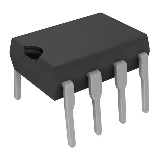
UC2842B/3B/4B/5B
UC3842B/3B/4B/5B
Minidip
comparator which also provides current limit control,
and a totem pole output stage designed to source
or sink high peak current. The output stage, suitable
for driving N-Channel MOSFETs, is low in the off-
state.
Differences between members of this family are the
under-voltage lockout thresholds and maximum duty
cycle ranges. The UC3842B and UC3844B have
UVLO thresholds of 16V (on) and 10V (off), ideally
suited off-line applications The corresponding thresh-
olds for the UC3843B and UC3845B are 8.5 V and 7.9
V. The UC3842B and UC3843B can operate to duty
cycles approaching 100%. A range of the zero to <
50 % is obtained by the UC3844B and UC3845B by
the addition of an internal toggle flip flop which blanks
the output off every other clock cycle.
5V
REF
INTERNAL
BIAS
VREF GOOD
LOGIC
T
S
R
PWM
1V
LATCH
CURRENT
SENSE
COMPARATOR
SO8
8
VREF
5V 50mA
6
OUTPUT
UC3842B
D95IN331
1/15
Advertisement


Need help?
Do you have a question about the UC2842B and is the answer not in the manual?
Questions and answers