
Related Manuals for Raycus RFL-C4000S


Summary of Contents for Raycus RFL-C4000S
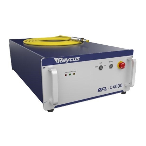
- Page 1 Continuous-Wave Fiber Laser User Guide RFL-C4000S Wuhan Raycus Fiber Laser Technologies Co., Ltd...
-
Page 2: Table Of Contents
Wuhan Raycus Fiber Laser Technologies Co., Ltd. User Guide of RFL-C4000S TABLE OF CONTENTS 1 Safety Information ........................3 1.1 Symbols Used in this User Guide ..................3 1.2 Laser Classification ......................3 1.3 Safety Labels ........................4 1.4 Optical Safety ........................5 1.5 Electrical Safety ........................ -
Page 3: Safety Information
User Guide of RFL- RFL-C4000S 1 Safety Information Thank you for choosing Raycus fiber laser. This User Guide provides important safety, operation, warranty and other information. Please read it carefully before you use this product. In order to ensure safe operation and optimal performance of the product, please follow the warnings, cautions, operating procedures and other instructions accordingly. -
Page 4: Safety Labels
1.3 Safety Labels The position of the safety labels on products varies depending on the model of the continuous- wave fiber laser, as shown in Figure 1: Figure 1: Safety Label Locations of RFL-C4000S... -
Page 5: Optical Safety
Wuhan Raycus Fiber Laser Technologies Co., Ltd. User Guide of RFL- RFL-C4000S These safety labels include warning labels, apertures through which laser radiation is emitted and labels of certification and identification, etc. Specifications of these labels are as follows: Table 1: Specifications of Safety Labels (Take 500W for example) 3.Class 2M Laser Product... -
Page 6: Other Safety Rules
(4) There are no operator serviceable parts inside, and all maintenance must be performed in Raycus or by qualified Raycus personnel. Do not try to remove covers, or electrical shock may be caused, and warranty will be void. -
Page 7: Product Description
➢ Cutting, Welding ➢ 3D Printing ➢ Scientific research 2.2 Model Configuration The series of Raycus continuous-wave fiber laser include1500W and 2000W, and the model designation codes are illustrated in the following table: Table 2 Model Names and Designation Codes RFL-C 4000S/B/20/W... -
Page 8: Package Contents
Check all items against the list and contact Raycus immediately if there is any missing item or evident damage to the unit. DO NOT attempt to install or operate the laser, if there is any evident or suspected damage to the unit. -
Page 9: Operation Environment
Wuhan Raycus Fiber Laser Technologies Co., Ltd. User Guide of RFL- RFL-C4000S CAUTION: The fiber optic cable and output head is precise optic instrument, any vibration or impact to the output head, and twist or excessive bend to the cable will damage the instrument. -
Page 10: Precautions For Use
AMBIENT DEW POINT Maximum Relative humidity Room Temperature(℃) -3.5 14.5 16.5 10.5 16.5 10.5 18.5 21.5 19.5 28.5 27.5 33.5 Laser operating temperature range ◆ Green area: The dew point temperature is 22℃ that is lower than the laser cooling water temperature, which can be used safely; ◆... -
Page 11: Specifications
Wuhan Raycus Fiber Laser Technologies Co., Ltd. User Guide of RFL- RFL-C4000S (5) Failure to follow the specified instructions may result in the loss of laser power, and such loss will not be covered by the warranty. 2.7 Specifications The specifications are listed in the following table... -
Page 12: Installation
3 Installation 3.1 Dimensions Figure 2 shows dimensions of RFL-C4000S. Figure 2 (a) Front panel view of RFL-C4000S (unit: mm) Figure2 (b) Rear panel view of RFL-C4000S (unit: mm) Figure2 (c) Top and Side view of RFL-C4000S (unit: mm) -
Page 13: Output Head And Installation
User Guide of RFL- RFL-C4000S 3.2 Output Head and Installation Figure 3 Dimensions of iQB Output Head The QBH and iQB laser output head of RFL-C4000S are all the standard QBH interface. The specific appearance and dimensions are shown in Figure 3 above. CAUTIONS: ◆... - Page 14 Figure 4, and then connect the water inlet filter module with the water inlet of the RFL-C4000S laser, as shown in Figure 5. Figure 5 The water inlet filtration module is connected to the water cooling system...
- Page 15 Wuhan Raycus Fiber Laser Technologies Co., Ltd. User Guide of RFL- RFL-C4000S ➢ It is recommended to use purified water. ➢ In order to prevent mould growing that may lead to pipe blockage, we recommend to add alcohol about 10% of the total volume.
-
Page 16: Installation Procedure
(4) Insert the water pipes into the inlet and outlet; (5) Check the output head and clean it if necessary. This procedure must be performed by personnel of Raycus or authorized by Raycus. Make sure the environment is clean, or the output cable may be contaminated. - Page 17 Wuhan Raycus Fiber Laser Technologies Co., Ltd. User Guide of RFL- RFL-C4000S (6) Prevent the delivery cable from treading, pinching or excessive bending during installation; (7) During the installation and disassembly process, please take care to handle the laser output head gently, avoiding any shock;...
-
Page 18: Using The Product
Please use the correct the latest PC software and the relevant manual. 4.1 Front Panel Figure 6 shows the front panel of RFL-C4000S: Figure 6 Front Panel of RFL-C4000S (1) REM/OFF/ON: Key switch, the control system power switch of the laser. Insert the key;... -
Page 19: Rear Panel
4.2 Rear Panel Figure shows the rear panel of RFL-C4000S: Figure 7 Rear Panel of RFL-C4000S (1) AC INPUT: The socket for supply source input that can only be mated with the plug on the power cord we provided. -
Page 20: Power Connection
6mm. If the CDA filter module provided by Raycus is used, the CDA should be also cooled and dried by the dryer, and the pressure should be below 0.8MPa, the outer diameter of pipe mated with the connector is 6mm. -
Page 21: Interface Definitions
Wuhan Raycus Fiber Laser Technologies Co., Ltd. User Guide of RFL- RFL-C4000S One end of the power cord is a plug, insert it into the socket Note 'AC INPUT' on the rear panel. Notice that the plug is wrong- side preventing. After inserting it, lock it with the lever. - Page 22 REMOTE mode, start Instantaneous the laser main power START-A Remote Start Contact Closure 24VDC <1s supply.Passive contact, not Button Input connected to external START-B voltage or grounding. Analog Input 1-10 VDC= Analog Input to 1-10V Analog Input 1-10VDC 1 mA 100us 10 –...
- Page 23 Wuhan Raycus Fiber Laser Technologies Co., Ltd. User Guide of RFL- RFL-C4000S and pin 1-4 before using the laser. If it is not short-circuited, the laser will display InterLock alarm after power-on. Interlock interface must not be connected to active signal, otherwise it will cause interface damage and laser alarm.
-
Page 24: Steps Of Installation
Figure 9 Steps of Ethernet Connection 4.5 Steps of Installation (1) Carefully take out the laser from the box and move it to the installing position and then lock the casters; Remove the output cable protective cap and check the output lens for dust with strong light and clean it if necessary, then cover the output cable protective cap;... -
Page 25: Functions Of The Clientware
(5) Turn on the key switch and start the laser. 4.7 Functions of the clientware The RFL-C4000S clientware communicates with the main control board through UDP when it is working. Through the background program running in the software and the human-computer interaction operation, the laser parameters are read and set and the control functions are realized. - Page 26 Figure 10 The clientware interface 4.7.1 The control interface The control interface is the content displayed on the first page after opening the clientware, including the user's most commonly used status signal, laser parameter setting and laser control related functions. Control the main power: turn on or off the main power.
- Page 27 Wuhan Raycus Fiber Laser Technologies Co., Ltd. User Guide of RFL- RFL-C4000S Read and Set Program Number: The program number is displayed in the drop-down list box. When you click the drop-down list box, the program number saved on the main control board is loaded.
- Page 28 Figure 11 The alarm interface 4.7.3 The Mode Selection function Select the operating mode of the software, including monitor mode, control mode, diagnostic mode, and debug mode. Figure 12 The Mode Selection function Monitor mode: The monitor mode is selected by default when the software is opened. The most commonly used and concerned information is displayed on the software interface to avoid the interference of too much information to the user.
-
Page 29: The Programming Mode (Waveform Editing)
Debug mode: On the basis of diagnostic mode, the parameter setting interface is added. Only Raycus debug engineers can enter the encryption mode. Diagnostic mode: When a fault occurs in the laser and the user needs to diagnose the fault remotely or learn more about the status of the laser, the user can enter the diagnostic mode.The... - Page 30 When the current program number of the laser is not 0, the laser runs in Program Mode.Please use the software of Raycus to edit the waveform, and select the program number of pre-run. The output waveform of laser is determined by the edited waveform. Under the condition that all...
- Page 31 Wuhan Raycus Fiber Laser Technologies Co., Ltd. User Guide of RFL- RFL-C4000S Figure 15 Interface diagram of programming setting Click the "Refresh List" button, and the software will automatically list the number of saved waveforms.Select the waveform number, the program will automatically list the original waveform list.Green indicates that the bar has a program, and white indicates that the bar is empty.
-
Page 32: Control Modes
Table 11 The waveform convenient command word detailed Command code Parameter 1 (2 bytes) Parameter 2 (4 bytes) Instructions (1 byte) Program end command, which STOP null null must be the last command of each program. It takes parameter 1 time to 0-65000(ms)... - Page 33 Wuhan Raycus Fiber Laser Technologies Co., Ltd. User Guide of RFL- RFL-C4000S External modulation or The laser enable button in the upper internal modulation ON. computer software. 4.9.1.3 External and internal modulation External modulation Internal modulation Laser 15, 16 pin voltage H—The laser emission...
- Page 34 Ethernet Ethernet cable Shorten(pin 1-4,and pin INTERLOCK 2-3) Rear panel of laser Power cord AC input supply source Figure 17 Internal control wiring diagram in key switch "ON" and clientware mode Operation method: ➢ Spring the “ESTOP” knob on the front panel; ➢...
- Page 35 Wuhan Raycus Fiber Laser Technologies Co., Ltd. User Guide of RFL- RFL-C4000S Ethernet Ethernet cable Shorten(pin 1-4,2-3) Rear panel INTERLOCK laser Pin 15,16 Modulation Power cord AC input supply source Figure 18 Wiring diagram of internal power control and external signal control in REM mode Operation method: ➢...
- Page 36 Ethernet Ethernet cable Shorten(pin 1-4,2-3) Rear panel Pin 15,16(MOD) INTERLOCK The Control laser card Pin 12,14(0-10V analog) Power cord AC input supply source Figure 3The power and laser are externally controlled wiring diagram in REM mode Operation method: ➢ Spring the “ESTOP” knob on the front panel; ➢...
-
Page 37: Steps Of Shutting Down
Wuhan Raycus Fiber Laser Technologies Co., Ltd. User Guide of RFL- RFL-C4000S The modulation frequency range of the RFL-C4000S laser is 1-5000Hz, and the minimum pulse width of the laser must be greater than or equal to 160us. Table 12 for reference values of the laser frequency and duty cycle. -
Page 38: Alarms And Solutions
5.1 Alarms Display When the laser establishes communication with the client software, all alarm states of the laser can be displayed on Raycus clientware, as shown in Figure (Download the Rsycus software and software manual, please log in to Raycus official website) - Page 39 Wuhan Raycus Fiber Laser Technologies Co., Ltd. User Guide of RFL- RFL-C4000S Table 7 Instructions and solutions for alarms of laser Alarm name Alarm instructions and solutions Instruction: Low temperature/high temperature alarm of the laser. The sensor in the laser detects an abnormal temperature inside the laser.
-
Page 40: Warranty, Return And Maintenance
The warranties start on the date of shipment from Raycus for a period of time as set forth in the applicable purchase contracts or product specifications. Raycus has the right to choose to repair or replace any product that proves to be defective in materials and workmanship selectively during the warranty period. -
Page 41: Service And Repair
Raycus due to excessive use or not following the instructions. Customer has the responsibility to understand and follow this instruction to use the device. Any damage caused by fault operating is not warranted.
Need help?
Do you have a question about the RFL-C4000S and is the answer not in the manual?
Questions and answers