
Related Manuals for CBE PC180-ST


Summary of Contents for CBE PC180-ST
- Page 1 NEW TECHNOLOGY PC180-ST ISTRUZIONI D’USO USER’S MANUAL BEDIENUNGSANLEITUNG INSTRUCTIONS D’EMPLOI ed. 09/2019 cod. 000400 Rev.04 ELECTRONICS FOR CARAVANNING...
-
Page 3: Table Of Contents
Elementi principali del sistema elettrico Consigli e verifiche PANNELLO COMANDO “PC180-ST” Descrizione Funzioni QUADRO DISTRIBUZIONE “DS300-ST” Fusibili di protezione Collegamenti Funzioni del sistema SCHEMA D’INSTALLAZIONE “PC180-ST” SCHEMA ELETTRICO “PC180-ST” Main parts of the electrical system dvice and checks ONTROL PANEL “PC1 0 8 -ST ”... - Page 4 Beschreibung Funktionen VERTEILUNGSMODUL “DS300-ST” Sicherungen Anschlüsse Funktionen EINBAUPLAN “PC180-ST” ELEKTRISCHER PLAN “PC180-ST” Elements principaux du systeme electrique Conseils et controles PANNEAU DE COMMANDE “PC180-ST” Descriptions ctions TABLEAU DE DISTRIBUTION DS300-ST “ ” Fusibles de protection Branchement Fonctions SCHEMA D’INSTALLATION “...
-
Page 5: Elementi Principali Del Sistema Elettrico
ELEMENTI PRINCIPALI DEL SISTEMA ELETTRICO > PANNELLO COMANDO “PC180-ST” - comando utenze, test batterie, test serbatoi. > QUADRO DI DISTRIBUZIONE 12V “DS300 ” - relè generale, relè parallelo batterie (12V-70A), relè frigo, relè pompa, dispositivo di ricarica batteria motore, fusibili di protezione. -
Page 6: Pannello Comando "Pc180-St
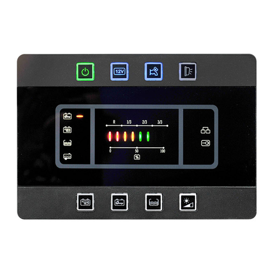
PANNELLO COMANDO “PC180-ST” DESCRIZIONE Pulsante generale ON/OFF di comando utenze 8) Pulsante con sensore crepuscolare integrato il settaggio dell intensit ’ à della retro- l lampeggio del led indica la batteria servizi illuminazione a led in situazione “notte” (vedi scarica ed il prossimo intervento del dispositivo anche funzione “CREPUSCOLARE”). -
Page 7: Funzioni
FUNZIONI ALLARME BATTERIA MOTORE (B1) SPEGNIMENTO AUTOMATICO Quando la batteria motore raggiunge una tensione DELLA LUCE ESTERNA inferiore a 12V si attiva automaticamente l’allarme Un dispositivo elettronico spegne automaticamente batteria motore scarica e il simbolo rif. 9 lampeggia la luce esterna con motore acceso. ALLARME BATTERIA SERVIZI (B2) FUNZIONE CREPUSCOLARE Quando la batteria... -
Page 8: Quadro Distribuzione "Ds300-St
QUADRO DI DISTRIBUZIONE “DS300-ST” 1 2 3 4 FUSIBILI DI PROTEZIONE Fusibile 5A per l' alimentazione della luce esterna. 8) Fusibile 25A per l’alimentazione del gradino elettrico, collegata direttamente alla batteria Fusibile 10A per l' alimentazione della pompa servizi (B2). acqua. -
Page 9: Collegamenti
’ “ ”) + entrata segnale contatto chiave avviamento motore 16A) + entrata segnale rete “ ” S proveniente dal carica batt erie CBE SEGNALI (POSSIBILITA ’ “B ) ” - entrata segnale negativo “D+” (-) entrata segnale contatto chiave avviamento motore... -
Page 10: Funzioni Del Sistema
FUNZIONI DEL SISTEMA Funzionamento con SMART ALTERNATOR RICARICA BATTERIA MOTORE (B1) (presente sui quadri distribuzione DS300 prodotti Con carica batterie in funzione, un dispositivo a partire da settembre 2019): elettronico consente una ricarica ( corrente nominale Per i veicoli dotati di SMART ALTERNATOR, un 2A) della batteria motore (B1), il sistema provvede a dispositivo elettronico gestisce le funzioni D+ con dare priorità... -
Page 11: Main Parts Of The Electrical System
MAIN PARTS OF THE ELECTRICAL SYSTEM > CONTROL PANEL “PC180-ST” - mains’ control, battery test, tank test. > 12V DISTRIBUTION BOX “DS3 0-ST” - main relais, battery parallel relais (12V - 70A), fridge relais, pump relais, car battery recharging device, protection fuses. -
Page 12: Control Panel "Pc1 0 8
CONTROL PANEL “PC180-ST” DESCRIPTIONS Mains’ general button ON/OFF; LED flashing If this symbol blinks the car battery (B1) has run indicates that the battery is low and that the low down. voltage device will turn on. 10) If this symbol blinks the leisure battery (B2) has NOTE: at start-up, the panel verifies the run down. -
Page 13: Functions
FUNCTIONS AWNING LIGHT AUTOMATIC TURN OFF CAR BATTERY ALARM (B1) An electronic device switches off the awning light battery voltage is lower than V, car when engine is turned on. battery alarm is automatically activated together with symbol ref. blinking. TWILIGHT FUNCTION In a “night”... -
Page 14: Distribution Box "Ds300-St
DISTRIBUTION BOX “DS300-ST” 1 2 3 4 PROTECTION FUSES 5A fuse to give power to the awning light. 25A fuse for the electrical step power supply, connected directly to the leisure (B2) battery. 10A fuse to give power to the water pump. 3A fuse for the gas power supply (fridge, 10A fuse to give power to the heating/boiler. -
Page 15: Connections
To connect to the 16 poles connector of the control panel. SIGNALS (OPTION A ) “ ” + input signal contact key engine starting. 16A) + input signal “S” net coming from the CBE battery charger. SIGNALS (OPTION “B ”) - input “D+” negative signal (-) + input signal contact key engine starting. -
Page 16: Electrical System Functions
ELECTRICAL SYSTEM FUNCTIONS Operation with SMART ALTERNATOR (present on CAR BATTERY (B1) RECHARGING all DS300 distribution boxes manufactured since When the battery charger is charging, an electronic September 2019): device allows a recharging ( nominal current 2 A) of For vehicles equipped with SMART ALTERNATOR the car battery (B1), the system gives priority to the n electronic device switches on the D+ functions leisure battery (B2). -
Page 17: Hauptelemente Der Elektrischen Anlage
HAUPTELEMENTE DER ELEKTRISCHEN ANLAGE > KONTROLLPANEL “PC180-ST” - Steuerung der Verbraucher, Batterie-Test, Tank-Test. > 12V VERTEILUNGSMODUL “D 3 0-S ” T - Hauptrelais, Batterie-Parallel Relais (12V - 70A), Kühlschrankrelais, Pumpenrelais, Ladungseinrichtung B1, Schutzsicherungen. > SONDE MIT STÄBEN - misst den Inhalt des FW-Tanks, 4-Stände Visualisierung. -
Page 18: Kontrollpanel "Pc180-St
KONTROLLPANEL “PC180-ST” BESCHREIBUNG Haupttaster ON/OFF zur Steuerung der Taste mit integriertem Dämmerungssensor zur Verbraucher; das Blinken der LED zeigt an, Einstellung der Intensität der LED- dass die Batterie leer wird und der Hintergrundbeleuchtung bei Dunkelheit siehe Tiefentladungsschutz in Kürze aktiviert wird. -
Page 19: Funktionen
FUNKTIONEN AUTOMATISCHE SCHALTUNG DE FAHRZEUG BATTERIE ALARM (B1) Wenn die Fahrzeug-Batterie eine Spannung < als VORZELTLEUCHTE 1 V erreicht, geht das Alarm Fahrzeug-Batterie Eine elektronische Einrichtung schaltet d ie automatisch an und blink d t as Symbol ref. . Vorzeltleuchte bei laufendem Motor automatisch aus. -
Page 20: Verteilungsmodul "Ds300-St
VERTEILUNGSMODUL “DS300 ” 1 2 3 4 SICHERUNGEN 5A Sicherung für die Versorgung des 25A Sicherung für die Versorgung der Vorzeltlichtes. elektrischen Trittstufe, sie hängt direkt von B2 10A Sicherung für die Versorgung der 3A Sicherung für die Gasversorgung Wasserpumpe. (Kühlschrank, Küche, Boiler-Ventil u.s.w.). -
Page 21: Anschlüsse
“ ” Signaleingang “D+” negativ (-) + Signaleingang Motorstarter Schlüsselkontakt. 16B) + Signaleingang “S” Netz, das aus dem CBE Ladegerät kommt. SICHERUNG VERBRAUCHER + Ausgang aux (Solarregler), direkt “ B2” 2-3) + Ausgang AES- Absorberkühlschrank. + Ausgang Trittstufe, direkt “... -
Page 22: Funktionen
FUNKTIONEN Betrieb mit SMART ALTERNATOR (auf allen FAHRZEUG BATTERIE (B1) MITLADUNG DS300 vorhanden, die seit September 2019 Mittels Ladegerät: Eine elektronische Einrichtung hergestellt werden): (die vom Mikroprozessor gesteuert wird) erlaubt Für Fahrzeuge mit SMART ALTERNATOR, schaltet eine itladung ( nennstrom 2 A) von der Fahrzeug- eine elektronische Einrichtung die D+ Funktionen bei Batterie B1 . -
Page 23: Elements Principaux Du Systeme Electrique
ELEMENTS PRINCIPAUX DU SYSTEME ELECTRIQUE > PANNEAU DE COMMANDE “PC180-S ” T - commande utilisations, test batterie, test réservoirs. > TABLEAU DE DISTRIBUTION 12V “DS300 ” - relais générale, relais parallèle batterie (12V-70A), relais frigo, relais pompe, dispositif de recharge batterie moteur, fusibles de protection . >... -
Page 24: Panneau De Commande "Pc180-St
PANNEAU DE COMMANDE “PC 180- T S ” DESCRIPTIONS Bouton général ON/OFF de commande Bouton avec capteur crépusculaire intégré pour le réglage de l’intensité du rétro-éclairage à Led utilisations, le clignotement de la led signale que la batterie est à plat et indique la en situation «... -
Page 25: Fonctions
FONCTIONS EXTINCTION AUTOMATIQUE DE ALARME BATTERIE MOTEUR (B1) Lorsque la batterie moteur atteinte une tension L’ÉCLAIRAGE EXTERIEUR inférieure à 1 V l'alarme batterie moteur decharg e é Un dispositif électronique éteint automatiquement s'active utomatiquement et le symbole réf. l’éclairage extérieur une fois que le moteur a clignote. -
Page 26: Tableau De Distribution Ds300-St
TABLEAU DE DISTRIBUTION “DS 300-ST ” 1 2 3 4 FUSIBLES DE PROTECTION Fusible 5A pour l’alimentation de la lumière Fusible 25A pour l’alimentation du marche-pied extérieure. électrique, il dépend directement de la batterie service (B2). Fusible 10A pour l’alimentation de la pompe à Fusible 3A pour l’alimentation du gaz eau. -
Page 27: Branchement
A brancher au connecteur 16 pôles du panneau de commande. SIGNALS (CHOIX A ) “ ” 1) + entrée singal contact clef démararrage moteur 16A) 2 ) + entrée signal réseau “S” qui viens du chargeur batterie CBE. SIGNALS (CHOIX B ) “ ” entrée signal “D+” négatif (-) + entrée singal contact clef démararrage moteur... -
Page 28: Fonctions
FONCTION Fonctionnement avec SMART ALTERNATOR RECHARGE BATTERIE MOTEUR (B1) (présent sur les tableaux de distribution DS300 Avec chargeur batteries: un dispositif électronique produits à partir de septembre 2019): permit une recharge ( courant nominal 2A) de la our les véhicules équipés du SMART ALTER batterie moteur (B1) -
Page 29: Schema D'installazione "Pc180-St
INSTALLATION “PC180-ST”... -
Page 30: Schema Elettrico "Pc180-St
WIRING DIAGRAM PC180-ST” “... - Page 31 NOTE...
- Page 32 CBE S.r.l. Via Vienna 4 z.i. Spini (settore D) 121 Trento - Italy Tel. +39 0461 991598 Fax +39 0461 960009 cbe@cbe.it www.cbe.it ELECTRONICS FOR CARAVANNING...
Need help?
Do you have a question about the PC180-ST and is the answer not in the manual?
Questions and answers