
Related Manuals for CBE PC210-ST


Summary of Contents for CBE PC210-ST
- Page 1 NEW TECHNOLOGY PC210-ST ISTRUZIONI D’USO USER’S MANUAL BEDIENUNGSANLEITUNG INSTRUCTIONS D’EMPLOI ed. 09/2019 cod. 000550 Rev.04 ELECTRONICS FOR CARAVANNING...
-
Page 3: Table Of Contents
Elementi principali del sistema elettrico Consigli e verifiche PANNELLO COMANDO “PC210-ST” Descrizione Videata principale Funzioni Programmazione utente QUADRO DISTRIBUZIONE “DS300-ST” Fusibili di protezione Collegamenti Funzioni del sistema SCHEMA D’INSTALLAZIONE “PC210-ST” SCHEMA ELETTRICO “PC210-ST” Main parts of the electrical system dvice and checks ONTROL PANEL “PC210-ST”... - Page 4 Kundenprogrammierung VERTEILUNGSMODUL “DS300-ST” Sicherungen Anschlüsse Funktionen EINBAUPLAN “PC210-ST” ELEKTRISCHER PLAN “PC210-ST” Elements principaux du systeme electrique Conseils et controles PANNEAU DE COMMANDE “PC210-ST” Descriptions Visualisation Fonctions Programmation utilisateur TABLEAU DE DISTRIBUTION “DS300-ST” Fusibles de protection Branchement ctions SCHEMA D’INSTALLATION “PC210-ST”...
-
Page 5: Elementi Principali Del Sistema Elettrico
ELEMENTI PRINCIPALI DEL SISTEMA ELETTRICO > PANNELLO COMANDO “PC210-ST” - comando utenze, test batterie, test serbatoi. > QUADRO DI DISTRIBUZIONE 12V “DS300 ” - relè generale, relè parallelo batterie (12V-70A), relè frigo, relè pompa, dispositivo di ricarica batteria motore, fusibili di protezione. -
Page 6: Pannello Comando "Pc210-St
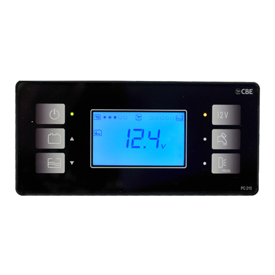
PANNELLO COMANDO “PC210-ST” DESCRIZIONE 1) Pulsante generale on/off (per accendere o Pulsante di comando delle luci e della stufa. spegnere premere per 2 secondi) all 'accensione 5) Pulsante per l’accensione e lo spegnimento della il display effettua un test di funzionamento pompa. -
Page 7: Videata Principale
VIDEATA PRINCIPALE Visualizzazione a barra dello stato della batteria 10) Indica il test del serbatoio acqu e chiare , il servizi “B2”. lampeggio indica l’allarme di serbatoio vuoto. Visualizzazione a barra dello stato del 11) Indica l 'allarme di serbatoio dell’acqua di serbatoio acqu e chiare... -
Page 8: Funzioni
FUNZIONI ALLARME BATTERIA MOTORE (B1) ARICO SERBATOIO ACQUE CHIARE Quando la batteria motore raggiunge una tensione Questa funzione viene utilizzata durante il carico inferiore a 12V si attiva automaticamente l’allarme dell’acqua del serbatoio acqu e chiare ed indica batteria motore scarica con il simbolo rif. -
Page 9: Programmazione Utente
PROGRAMMAZIONE UTENTE Premere per più di 2 secondi il pulsante “PROG” Per uscire dalla programmazione salvando le rif. 6 dalla videata principale per entrare in modifiche effettuate premere ripetutamente il programmazione . pulsante “PROG” rif.6 fino all'uscita automatica Variare i parametri desiderati utilizzando i pulsanti “SAV”. - Page 10 TARATURA VOLTMETRI Taratura della tensione della batteria servizi "B2". Il valore può essere regolato per un massimo di ±0.5V, con step di 0.1V. Taratura della tensione della batteria motore "B1". Il valore può essere regolato per un massimo di ±0.5V, con step di 0.1V. TEMPERATURE Taratura della temperatura esterna con step di 0.5°C.
-
Page 11: Quadro Distribuzione "Ds300-St
QUADRO DI DISTRIBUZIONE “DS300-ST” 1 2 3 4 FUSIBILI DI PROTEZIONE Fusibile 5A per l' alimentazione della luce esterna. 8) Fusibile 25A per l’alimentazione del gradino elettrico, collegata direttamente alla batteria Fusibile 10A per l' alimentazione della pompa servizi (B2). acqua. -
Page 12: Collegamenti
+ entrata segnale contatto chiave avviamento motore 16A) + entrata segnale rete “ ” S proveniente dal carica batt erie CBE SEGNALI (POSSIBILITA ’ “B ) ” - entrata segnale negativo “D+” (-) + entrata segnale contatto chiave avviamento motore... -
Page 13: Funzioni Del Sistema
FUNZIONI DEL SISTEMA Funzionamento con SMART ALTERNATOR RICARICA BATTERIA MOTORE (B1) (presente sui quadri distribuzione DS300 prodotti Con carica batterie in funzione, un dispositivo a partire da settembre 2019): elettronico consente una ricarica ( corrente nominale Per i veicoli dotati di SMART ALTERNATOR, un 2A) della batteria motore (B1), il sistema provvede a dispositivo elettronico gestisce le funzioni D+ con dare priorità... -
Page 14: Main Parts Of The Electrical System
MAIN PARTS OF THE ELECTRICAL SYSTEM > CONTROL PANEL “PC210-ST” - mains’ control, battery test, tank test. > 12V DISTRIBUTION BOX “DS3 0-ST” - main relais, battery parallel relais (12V - 70A), fridge relais, pump relais, car battery recharging device, protection fuses. -
Page 15: Control Panel "Pc210-St
CONTROL PANEL “PC210-ST” DESCRIPTIONS On/off main button (to turn on/off press for 2 Button to switch the lights and the heating/boiler seconds) at the start-up the display carries out a on and off . functioning test and shows all symbols Button to switch the pump on and off. -
Page 16: Main Visualizations
MAIN VISUALIZATIONS “ B2 leisure battery status display. ” It shows the unit of measure. Fresh water tank status display. 10) It shows the fresh water tank test, the blinking indicates the empty tank alarm. It shows the car battery (B1) test, the blinking 11) It displays that the waste water tank is full. -
Page 17: Functions
FUNCTIONS is getting filled: one short beep at 75%, two short CAR BATTERY ALARM (B1) beep at 85% and a long beep at 95%. When car battery voltage gets under 12V, car Battery Discharge alarm goes on and the symbol o exit this function press buttons ref. -
Page 18: Users's Setting
USER’S SETTING To enter the set mode, press the “PROG” button Press the “PROG” button (ref. ) 6 more than once (ref.6) for more than 2 seconds from the main to save the settings and exit the setting mode. screen. To exit without saving wait 20 seconds without By using the arrow keys ref. - Page 19 VOLTMETERS SETTING Setting of the leisure battery “B2” voltmeter. Max. value +/- 0.5V, step 0.1V. Setting of the car battery “B1” voltmeter. Max. value +/- 0.5V, step 0.1V. TEMPERATURES Setting internal temperature, step 0.5°C Setting external temperature, step 0.5°C...
-
Page 20: Distribution Box "Ds300-St
DISTRIBUTION BOX “DS300-ST” 1 2 3 4 PROTECTION FUSES 5A fuse to give power to the awning light. 25A fuse for the electrical step power supply, connected directly to the leisure (B2) battery. 10A fuse to give power to the water pump. 3A fuse for the gas power supply (fridge, 10A fuse to give power to the heating/boiler. -
Page 21: Connections
To connect to the 16 poles connector of the control panel. SIGNALS (OPTION A ) “ ” + input signal contact key engine starting. 16A) + input signal “S” net coming from the CBE battery charger. SIGNALS (OPTION “B ”) - input “D+” negative signal (-) + input signal contact key engine starting. -
Page 22: Electrical System Functions
ELECTRICAL SYSTEM FUNCTIONS Operation with SMART ALTERNATOR (present on CAR BATTERY (B1) RECHARGING all DS300 distribution boxes manufactured since When the battery charger is charging, an electronic September 2019): device allows a recharging ( nominal current 2 A) of For vehicles equipped with SMART ALTERNATOR the car battery (B1), the system gives priority to the n electronic device switches on the D+ functions leisure battery (B2). -
Page 23: Hauptelemente Der Elektrischen Anlage
HAUPTELEMENTE DER ELEKTRISCHEN ANLAGE > KONTROLLPANEL “PC210-ST” - Steuerung der Verbraucher, Batterie-Test, Tank-Test. > 12V VERTEILUNGSMODUL “D 3 0-S ” T - Hauptrelais, Batterie-Parallel Relais (12V - 70A), Kühlschrankrelais, Pumpenrelais, Ladungseinrichtung B1, Schutzsicherungen. > ELEKTRONISCHE SONDE - Misst den Wasserstand in den Tank, Anzeige in “%”. -
Page 24: Kontrollpanel "Pc210-St
KONTROLL PANEL “PC210-ST” BESCHREIBUNG Haupttaster on/off (Drücken ca. 2 Sekunden Taster für die Ein- u- Ausschaltung der Lichter um ein- oder auszuschalten): beim der Heizung/Boiler Einschalten führt das Display einen Taster für die Ein- u. Ausschaltung der Pumpe. Funktionstest durch und zeigt alle Symbole an Funktion A) Taster für die Ein- u- Ausschaltung... -
Page 25: Hauptanzeige
HAUPTANZEIGE Strich-Anzeige für Verbraucherbatterie-Stand 10) Signalisiert das Test des Frischwassertank , (B2). das Blinklicht signalisiert den leeren Tank. Strich-Anzeige für Frischwassertank-Stand. 11) Signalisiert dass der Abwassertank voll ist. Signalisiert, dass die Fahrzeugbatterie (B1) 12) Signalisiert, dass der Tiefentladungschutz an in Reserve ist. -
Page 26: Funktionen
FUNKTIONEN FAHRZEUG BATTERIE ALARM (B1) FRISCHWASSERTANK EINFÜLLUNG Diese Funktion dient der Frischwasser-Befüllung Wenn die Fahrzeug-Batterie eine Spannung unter und zeigt an, was für einen Tankstand das Wasser als 12V erreicht, geht das Alarm FZG-Batt-Entlade an und blinkt das Symbol ref. 3. Das Alarm geht aus erreicht hat. -
Page 27: Kundenprogrammierung
KUNDENPROGRAMMIERUNG Vom Startseite, den Taster “PROG” ref. 6 mehr als Den Taster “PROG” ref. 6 mehrmals drücken, um 2 Sekunden gedr ückt halten, um in das die Veränderungen zu speichern und das Programmierungsmenü einzutreten. Hauptmenü zu verlassen. Durch das Drücken der Pfeiltaster ref. 2 und 3 Um keine Veränderungen zu speichern und das das ausgewählte Parameter verändern. - Page 28 EICHUNG DER VOLTMETER Eichung der Spannung der Verbraucherbatterie“B2” Max Wert +/- 0,5V mit Abstand von 0,1V. Eichung der Spannung der Fahrzeugbatterie „B1“. Max. Wert +/- 0,5V mit Abstand von 0,1V. TEMPERATUREN Eichung der Innentemperatur mit Abstand von 0,5°C. Eichung der Aussentemperatur mit Abstand von 0,5°C.
-
Page 29: Verteilungsmodul "Ds300-St
VERTEILUNGSMODUL “DS300 ” 1 2 3 4 SICHERUNGEN 5A Sicherung für die Versorgung des 25A Sicherung für die Versorgung der Vorzeltlichtes. elektrischen Trittstufe, sie hängt direkt von B2 10A Sicherung für die Versorgung der 3A Sicherung für die Gasversorgung Wasserpumpe. (Kühlschrank, Küche, Boiler-Ventil u.s.w.). -
Page 30: Anschlüsse
“ ” Signaleingang “D+” negativ (-) + Signaleingang Motorstarter Schlüsselkontakt. 16B) + Signaleingang “S” Netz, das aus dem CBE Ladegerät kommt. SICHERUNG VERBRAUCHER + Ausgang aux (Solarregler), direkt “ B2” 2-3) + Ausgang AES- Absorberkühlschrank. + Ausgang Trittstufe, direkt “... -
Page 31: Funktionen
FUNKTIONEN Betrieb mit SMART ALTERNATOR (auf allen FAHRZEUG BATTERIE (B1) MITLADUNG DS300 vorhanden, die seit September 2019 Mittels Ladegerät: Eine elektronische Einrichtung hergestellt werden): (die vom Mikroprozessor gesteuert wird) erlaubt Für Fahrzeuge mit SMART ALTERNATOR, schaltet eine itladung ( nennstrom 2 A) von der Fahrzeug- eine elektronische Einrichtung die D+ Funktionen bei Batterie B1 . -
Page 32: Elements Principaux Du Systeme Electrique
ELEMENTS PRINCIPAUX DU SYSTEME ELECTRIQUE > PANNEAU DE COMMANDE “PC 0-S ” T - commande utilisations, test batterie, test réservoirs. > TABLEAU DE DISTRIBUTION 12V “DS300 ” - relais générale, relais parallèle batterie (12V-70A), relais frigo, relais pompe, dispositif de recharge batterie moteur, fusibles de protection . >... -
Page 33: Panneau De Commande "Pc210-St
PANNEAU DE COMMANDE “PC 210- T S ” DESCRIPTIONS Bouton général on/off (pour sa mise en service Bouton de commande des lumières et du chauffage / boiler. et hors service, appuyer 2 secondes): lors de l'allumage, l'afficheur effectue un test de Bouton de commande pompe eau, il fonctionnement en montrant tous les symboles commande le relais pompe. -
Page 34: Visualisation
VISUALISATION Affichage de l’état de la batterie des Indicateur de l’unité de mesure. services B2 . “ ” 10) Indique le test du réservoir eau propre , le Affichage de l’état du réservoir eau propre symbole clignote pour indiquer que le réservoir est vide. -
Page 35: Fonctions
FONCTIONS ALARME BATTERIE MOTEUR (B1) REMPLISSAGE RESERVOIR EAU PROPRE Cette fonction est utilisée pendant le remplissage Lorsque la batterie moteur atteinte une tension inférieure à 12V l'alarme “Batterie Moteur d’eau du réservoir eau propre, il indique le niveau Dechargee” s'active automatiquement et le symbol d’eau pendant le remplissage. -
Page 36: Programmation Utilisateur
PROGRAMMATION UTILISATEUR Pour entrer en programmation appuyer plus de Pour sauver le modifications et sortir du deux secondes le bouton “PROG” réf. 6 depuis la programmation appuyer plusieurs fois le bouton page-écran principale. “PROG” réf. 6. Modifier les paramètres voulus en utilisant les w Pour sortir sans sauver la modification attendre boutons en forme de flèche réf. - Page 37 REGLAGE DES VOLTMETRES Réglage de la tension de la batterie services «B2». Valeur max. +/- 0,5V par pas de 0,1V. Réglage de la tension de la batterie moteur «B1». Valeur max. +/- 0,5V par pas de 0,1V. TEMPERATURES Réglage témperature intérieure par pas de 0,5°C. Réglage témperature extérieure par pas de 0,5°C.
-
Page 38: Tableau De Distribution "Ds300-St
TABLEAU DE DISTRIBUTION “DS 300-ST ” 1 2 3 4 FUSIBLES DE PROTECTION Fusible 5A pour l’alimentation de la lumière Fusible 25A pour l’alimentation du marche-pied extérieure. électrique, il dépend directement de la batterie service (B2). Fusible 10A pour l’alimentation de la pompe à Fusible 3A pour l’alimentation du gaz eau. -
Page 39: Branchement
A brancher au connecteur 16 pôles du panneau de commande. SIGNALS (CHOIX A ) “ ” 1) + entrée singal contact clef démararrage moteur 16A) 2 ) + entrée signal réseau “S” qui viens du chargeur batterie CBE. SIGNALS (CHOIX B ) “ ” entrée signal “D+” négatif (-) + entrée singal contact clef démararrage moteur... -
Page 40: Fon Ctions
FONCTION Fonctionnement avec SMART ALTERNATOR RECHARGE BATTERIE MOTEUR (B1) (présent sur les tableaux de distribution DS300 Avec chargeur batteries: un dispositif électronique produits à partir de septembre 2019): permit une recharge ( courant nominal 2A) de la our les véhicules équipés du SMART ALTER batterie moteur (B1) -
Page 41: Schema D'installazione "Pc210-St
INSTALLATION “PC210-ST”... -
Page 42: Schema Elettrico "Pc210-St
WIRING DIAGRAM PC210-ST” “... - Page 43 NOTE...
- Page 44 CBE S.r.l. Via Vienna 4 z.i. Spini (settore D) 121 Trento - Italy Tel. +39 0461 991598 Fax +39 0461 960009 cbe@cbe.it www.cbe.it ELECTRONICS FOR CARAVANNING...
Need help?
Do you have a question about the PC210-ST and is the answer not in the manual?
Questions and answers
Why would the panel display the vehicle battery (B1) as 0v when the engine is turned on and functioning correctly?
The CBE PC210-ST panel may display the vehicle battery (B1) as 0V when the engine is on if the D+ signal or the “+ key” ON signal is missing. These signals are required to activate the D+ functions, including battery monitoring. If neither signal is present, the system does not detect the vehicle battery voltage, resulting in a 0V reading.
This answer is automatically generated