
Related Manuals for Label ETERNA 90 EASY


Summary of Contents for Label ETERNA 90 EASY
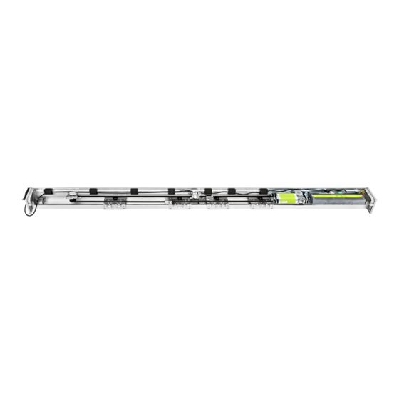
- Page 1 ETERNA 90 EASY Automation for automatic sliding doors ETERNA EASY 90 16005 - EN - Rel.1.0 - 03/2020 - CD0729EN...
-
Page 2: Table Of Contents
ABLE OF CONTENTS: GENERAL SAFETY WARNINGS GENERAL SAFETY OBLIGATIONS 1) DESCRIPTION OF THE MODELS 2) TECHNICAL SPECIFICATIONS OF THE ETERNA 90 EASY AUTOMATION 3) ETERNA 90 EASY AUTOMATION COMPONENTS 4) TECHNICAL DRAWINGS 4.1) TECHNICAL DRAWINGS - SPECIAL APPLICATIONS 5) COVERING CASING... -
Page 3: General Safety Warnings
This product is designed and built exclusively for the purpose described in this documentation. Any other use that is not specifically indicated could adversely impact the condition of the product and the safety of people. Label accepts no responsibility for incorrect product installation and usage, as well as for any damage caused by changes made without its prior consent. -
Page 4: Description Of The Models
1 - DESCRIPTION OF THE MODELS The ETERNA 90 EASY automation has been designed and manufactured for the control of pedestrian automatic sliding doors. A list of the ETERNA 90 EASY sliding door automation models produced by Label is provided below: ETERNA 90 EASY D Automation for double door leaf, max. -
Page 5: Eterna 90 Easy Automation Components
3 - ETERNA 90 EASY AUTOMATION COMPONENTS side panel pair upper belt coupling ET-LOGIC-EASY control unit lower belt coupling ET-MOT 90 motor unit with encoder cable gland fall prevention cables return pulley double wheel carriage mechanical limit switch driving belt... -
Page 6: Technical Drawings
4) TECHNICAL DRAWINGS LEGEND: LT = TRANSOM LENGTH (WITHOUT SIDE COVERS) PL = FREE PASSAGE LM = LEAF WIDTH = LIMIT DEVICE = OVERLAP LEAF DOUBLE LEAF LT = TRANSOM PL = FREE PASSAGE LM = LEAF WIDTH F = IDLE PULLEY *M = MOTOR PULLEY LC = BELT LENGTH E = ELECTRIC LOCK... -
Page 7: Technical Drawings - Special Applications
Installation examples: If presence sensor 3H-IR14C (V00247 - Label Price List Code) must be mounted flush with its mounting bracket V00246 - Label Price List Code. In the case of dual leaf automation whose length is less than LT<2300 mm. -
Page 8: Covering Casing
5 - COVERING CASING The casing of the ETERNA 90 EASY automation is provided with two fall prevention cables (A) designed to ensure its stability in the opening position (Fig.1). FIG.1 Insert the two fall prevention cables in the seats located on the transom and on the casing with the ends facing the same direction. -
Page 9: Belt Tightening Adjustment
6 - BELT TIGHTENING ADJUSTMENT To adjust belt tightening, slightly loosen the A screw of the idle pulley, then screw in (to increase belt tightening) or unscrew (to decrease belt tightening) the hexagonal screw B. After achieving the optimum driving belt tightening fully tighten screw A. - Page 10 DOUBLE LEAF WITHOUT ELECTRIC LOCK FIG. 9 DOUBLE LEAF WITH ELECTRIC LOCK FIG. 10 LEFT CLOSING SINGLE LEAF WITH ELECTRIC LOCK OPENING DIRECTION FIG. 11 RIGHT CLOSING SINGLE LEAF WITH ELECTRIC LOCK OPENING DIRECTION FIG. 12...
-
Page 11: Installation Measures
9 - INSTALLATION MEASURES The transom must be fastened to a flat surface solid enough to bear the weight of the leaves to be used. If the wall or the support do not meet these characteristics you will have to provide a suitable tubular element, as the transom is not self-bearing. - Page 12 SECTION WITH COMMERCIAL PROFILES SECTION WITH LB35 PROFILE SYSTEM DIMENSIONAL TABLE LEGEND: AUTOMATION LENGTH FREE PASSAGE LEAF WIDTH FINAL LEDGES LEAF OVERLAPPING 1 MOBILE LEAF 2 MOBILE LEAVES Sizing mm Sizing mm LT= automation length LM= leaf S= overlap PL = free passage LT= automation length LM= leaf S= overlap PL = free passage...
-
Page 13: Electric Locks
10 - ELECTRIC LOCKS 10.1) GENERAL DESCRIPTION The electric lock for the ETERNA 90 EASY automation is available in 3 models, which have different behaviour during a power failure. a) FAIL SAFE «ET-FSA» In the case of a power failure, of both mains power supply and emergency battery power, the electric lock will release the leaves, which can then be moved manually. - Page 14 10.3) MANUAL RELEASE The models Fail Secure ET-FSE and Bistable ET-BIS are equipped with the ET-SMA manual release system that is used to release the electric lock in the case of a power failure, and therefore move the leaves freely. RELEASE HANDLE FASTENING For fastening on both the right and left side of the automation, you need to fasten the adjustment register on the bottom of the...
- Page 15 Apply the screw cover label on the fastening screw. By moving the release handle to the UNRELEASED position, SCREW COVER only the orange part of the label with the drawn arrows must be LABEL visible. Insert the flexible sheath inside the side panel.
- Page 16 Insert the sheath using the cable guides until reaching the electric lock. Cut off the excess sheath. Insert the steel cable into the release handle and into the sheath until reaching the electric lock. Fit the sheath end on the tip of the sheath which has been cut. Position the compression spring and insert the metal cable inside the special release anchor, then lock it with the screw clamp.
- Page 17 Check manual release operation, when the handle is in locked position, the electric lock must operate normally. When the handle is in released position, the electric lock must remain open and release the leaves. Cut the excess steel cable from the release anchor. NOTE: In case of FAIL SECURE electric lock, by releasing the release, the electric lock will close.
- Page 18 Drill the wall and fasten the base of the release mechanism using the fastening screws. Apply the adhesive label as shown in the figure, taking the four black bands on the label as a reference, which must be Identify the fastening point on the wall, taking into account that positioned in correspondence of the 4 cardinal points.
-
Page 19: Electric Connections
N° 1 CABLE 8 x 0,5 mm door opening and safety during closing N° 1 CABLE 6 x 0,5 mm Opening safety sensor Key button N° 1 CABLE 2 x 0,5 mm ETERNA 90 EASY automation N° 1 CABLE 3 x 1,5 (F-N-T) - Page 20 ELECTRICAL CONNECTIONS ETERNA EASY 90 Application with two opening sensors and safety photocell mod. PRJ38 INTERNAL RADAR EXTERNAL RADAR OUTPUT POWER OUTPUT POWER SUPPLY SUPPLY N.O. N.O. POWER SUPPLY PRJ38P PRJ38P SWITCH RAD. +24V RAD. +24V 230Vac BLUE BROWN ELECTRIC LOCK BATTERY 18V FAIL SAFE T-EASY...
- Page 21 ELECTRICAL CONNECTIONS ETERNA EASY 90 Application with two OA-FLEX - activation and safety sensor in closing To activate the operating of the safety sensor in closing EC1 set dip-switch 1 of S3 = OFF To activate the operating of the safety sensor in closing EC2 set dip-switch 1 of S2 = ON To activate the closing safety sensor test set dip-switch 3 of S2 = ON (as request by EN16005 European standard) Set safety input "LOW"...
- Page 22 ELECTRICAL CONNECTIONS ETERNA EASY 90 Application with two OA-PRESENCE T safety sensor in opening To activate the operating of the safety sensor in opening EO1 set dip-switch 2 of S3 = OFF. To activate the operating of the safety sensor in opening EO2 set dip-switch 2 of S2 = ON. To activate the opening safety sensor test set dip-switch 4 of S2 = ON (as request by EN16005 European standard) Set safety input "LOW"...
- Page 23 ELECTRIC CONNECTION DESCRIPTION On the plastic side panels of the ETERNA 90 EASY automation (part 1 in figure in para. 3) there is a hole that must be broken open, through which the electric cables must be inserted. Along the upper part of the aluminium transom, there are various plastic cable guides (part 8 in the figure in para. 3) inside which the cables should be run.
- Page 24 • TERMINAL BOARD M4 (Inputs 10, 11, 12) 10 = Input of closing safety sensor E.C.1; N.C. contact. The operation of the closing safety sensor EC1 must be enabled by dip-switch 1 of S3 = OFF. If during closing it detects the presence of an obstacle, the door stops and reopens. If during pause it detects the presence of an obstacle, the door remains open.
-
Page 25: Commissioning Of Automatic Door (Initial Set-Up)
12) COMMISSIONING OF AUTOMATIC DOOR (INITIAL SET-UP) After performing the mechanical installation of the automatic door and the electrical connections to the electronic control unit, make the automation set-up. • Preliminary checks: - check the cleanliness of the sliding rail and of the ground guide; - check the belt’s tension;... -
Page 26: Functions And Potentiometers
13) FUNCTIONS and POTENTIOMETERS DIP-SWITCH AND POTENTIOMETERS SETTINGS Carefully read this paragraph to learn how to adjust the dip-switch S1, S2 and potentiometers from TM1 to TM6. After changing the dip-switch and potentiometers settings make sure to confirm through the "PS3 FUNCTION" red button in the following way: 1. - Page 27 FUNCTION TABLE DIP-SWITCH S1 FUNCTION STATUS EXPLANATION Automation type selection: ETERNA EASY 150 (doors up to a maximum weight of 150 kg per leaf). DIP 1 Automation type selection: ETERNA EASY 90 (doors up to a maximum weight of 90 kg per leaf). Electric lock type selection: ET-FSE - FAIL SECURE DIP 2 Electric lock type selection: ET-FSA - FAIL SAFE...
- Page 28 FUNCTION TABLE DIP-SWITCH S2 FUNCTION STATUS EXPLANATION E. E.C.2 closing safety sensor input inactive When the safety sensor is not installed on the E.C.2 - AUX1 input (terminal 13-14). DIP 1 E. E.C.2 closing safety sensor input active Closing safety sensor installed on E.C.2 - AUX1 input (terminal 13-14). See electrical connections “drawing 2”.
- Page 29 POTENTIOMETERS TABLE POTENTIOMETER EXPLANATION Opening speed. Max. 0,8 m/s per leaf. Increasing the value will increase speed during the opening process. Closing speed. Max. 0,6 m/s per leaf. Increasing the value will increase speed during the closing process. Reduced opening distance during winter. Min. 20 cm per leaf. Adjustment of the reduced opening space in percentage of the free passage.
-
Page 30: Function Testing
14) ) FUNCTION TESTING Select door automatic operation by program selector. To start an opening cycle give a pulse to PS2 button (Start) on the ET-LOGIC-EASY control unit or activate the door opening devices. Ensure that door opening and closing cycle is properly performed and that activation commands and safety sensors work properly. -
Page 31: Input Diagnostic
15) ) INPUT DIAGNOSTIC Each input of the ETERNA-EASY electronic control unit is shown by the relative LED on the board. Below the table with the correspondence between LED and relative input. LED 1 24V: it lights up when the control unit is powered. LED 2 Battery status: see table LED SIGNALLING on paragraph “BATTERY-POWERED EMERGENCY OPENING DEVICE”. -
Page 32: T-Easy Selector Program
16) T-EASY SELECTOR PROGRAM The T-EASY selector uses the Touch technology for the buttons and features a next-generation, high-contrast display for clearer images. It is used to interface with the door during “standard” operation by the user. For faster installation and to eliminate the risk of connection errors, the selector is equipped with a special cable (3,5 metres long), with a built-in connector at both ends. - Page 33 Insert the other terminal of the cable to J7 connector on the control unit ET-LOGIC EASY. After completing all the electrical connections to the electronic control unit of the automation, power the automatic door. When installed for the first time, the selector shall automatically switch to the language selection menu.
- Page 34 The door opens and remains open until the operating program is changed. OPEN: CLOSED DOOR. The door can only be opened automatically through specific inputs (Open, LOCK: RX and START). Every time the door is closed, the electric lock, if any, is activated. OFF: The door can be freely moved manually and does not react to the activation of any input.
- Page 35 USER PASSWORD MANAGEMENT The T-EASY selector allows to password-protect the operating program change. This function is useful if you wish to prevent unauthorised people from setting the door operating program. To this purpose, you need to enable the user password, by following the procedure described below. Hold the D button pressed for about 2 seconds.
- Page 36 TECHNICAL AREA By means the T-EASY you can set the selector option and language. Hold the SET button pressed for about 2 seconds to enter the technical area. The following are the 2 menus available in the technical area: 3 -- SELECTOR OPTION 4 -- LANGUAGE To switch from the menù...
- Page 37 The last customisable parameter, finally, is: • Selector activation with “SLIDE” (>>>) This function allows to activate the selector, when it is in screen saver mode, by just swiping with a finger from left to right in the bottom section of the digital selector, near the A-SET-B buttons. Although not an actual password (which anyway can be set as described in the paragraph “USER PASSWORD MANAGEMENT”), it still allows to ensure that the operating program adjustment menu can only be accessed if one is aware of this option.
-
Page 38: Battery-Powered Emergency Opening Device
BATTERY-POWERED EMERGENCY OPENING DEVICE 17.1) ET-BAT90 Assembly of the battery pack The battery containment plate is mounted on the back of the module ET-DRIVE/EASY using the hexagon socket head cap screws 4x6. Remove the container of the electronic control unit by unscrewing the two screws M5x10. - Page 39 Operation The ET-BAT90 device trips in case of mains power failure, allowing the ETERNA 90 EASY operator to keep running. The battery operating time depends on various factors, like the number of operations performed, the leaf weight, the connected external devices , etc..
- Page 40 17.2) BATTERY DEVICE ET-BAT90P BATTERY TYPE: RECHARGEABLE SEALED LEAD SPECIFICATIONS Nominal Voltage 18V (3x6V) Nominal Capacity 1.3Ah Operating Temperature Range -15°C to 50°C BATTERY PACK location inside the ETERNA 90 EASY automation...
- Page 41 Operation The ET-BAT90P device trips in case of mains power failure, allowing the ETERNA 90 EASY operator to keep running. The battery operating time depends on various factors, like the number of operations performed, the leaf weight, the connected external devices , etc..
-
Page 42: Prj38 Photocells
18) PRJ38 PHOTOCELLS The pair of PRJ38 Label photocells consists of a transmitting and a receiving capsule. The transmitting capsule, besides, is equipped with a 2-wire cable bearing the PRJ38-TX mark, while PHOTO PRJ38 RX the receiving capsule has a 3-wire cable bearing the PRJ38-RX mark. -
Page 43: Radioreceiver En/Rf1
Marketing, sale and use are valid without restrictions in all EU countries. With this document Label SpA declares that the receiver EN-RF1 complies with all the essential requirements and with all other relevant provisions established by the directive RED 2014/53/EC. - Page 44 LED LAMPEGGIANTE VELOCE - LED BLINKING FAST - LED À CLIGNOTEMENT RAPIDE DIODO EMISOR DE LUZ DESTELLANDO RÁPIDO memorizzazione di tutti i modelli di trasmettitori Label - saving of all Label transmitter models under way mémorisation de tous les modèles de transmetteurs Label - memorización de todos los modelos de transmisores Label LED LAMPEGGIANTE MOLTO VELOCE - LED BLINKING VERY FAST - LED À...
-
Page 45: Meaning Of Buzzer Warning Signals
Check that motion speeds, involved forces, and installed safety devices are working appropriately. • Clean sensors and check that presence detectors activate properly. Warning! Any potentially damaged or worn component must be replaced. Make use only of original spare parts; for this purpose check LABEL Parts list. -
Page 46: Declaration Of Incorporation Of Partly Assembled Machinery
• Electromagnetic compatibility directive EMC 2014/30/EU Label declares that the automation ETERNA 90 EASY has been realized to be incorporated in a machinery or to be assembled with other devices to constitute a machinery covered by Machine Directive 2006/42/EC. Harmonized European regulations applied:... - Page 47 notes...
- Page 48 ETERNA easy Made in Italy by S.p.A. Via Ilariuzzi, 17/A - S. Pancrazio P .se - 43126 PARMA - ITALIA Tel. (+39) 05 21/ 67 52 - Fax (+39) 05 21/ 67 52 22 infocom@labelspa.it - www.labelspa.com...
Need help?
Do you have a question about the ETERNA 90 EASY and is the answer not in the manual?
Questions and answers