Table of Contents
Advertisement
Advertisement
Table of Contents

Related Manuals for DoAll 500SNC


Summary of Contents for DoAll 500SNC
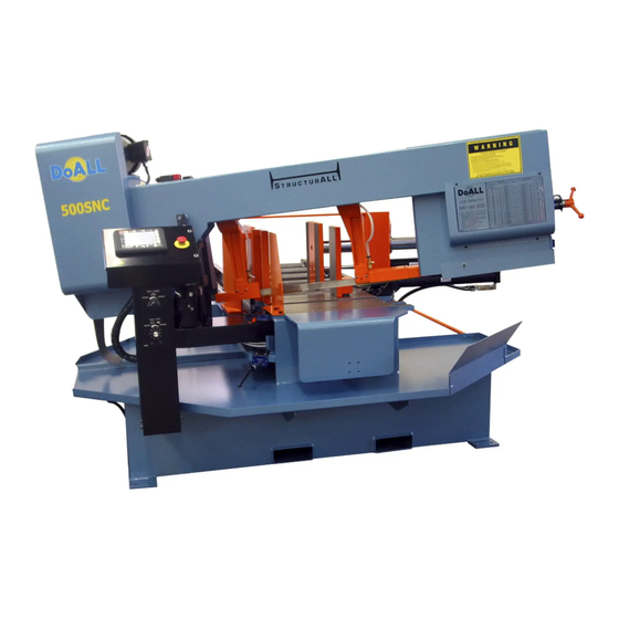
- Page 1 500SNC Serial No: 592-13178 to Band Sawing Machine...
- Page 2 DAMAGE CLAIM PROCEDURES VISIBLE DAMAGE AT THE TIME OF DELIVERY: Note damage on carrier’s delivery receipt. Accept the shipment. It can be returned later if repairs are not possible in the field. Request a “damage inspection” from the delivery carrier: The carrier will send his own people or contract an independent agency to make the inspection.
- Page 3 For Sales, Parts and Service, call 1-888-362-5572 DoALL SAWING PRODUCTS 2375B TOUHY AVENUE ELK GROVE, ILLINOIS 60007 U.S.A. The following registered trademarks of the DoALL Company are used in this manual: DoALL, Imperial Bi-Metal, Kleen-Kool, and Tensigage. PRINTED IN U.S.A. PB-541.3 (5-13)
-
Page 4: Table Of Contents
TABLE OF CONTENTS LUBRICATION MACHINE DIMENSIONS Lubrication Chart ......................Floor Plan Lubrication Diagrams ..........Top View ..............Front View .............. MAINTENANCE MACHINE FEATURES Saw Guide Insert Replacement ......Drive Belt Removal or Replacement ................. Front View Band Tension Adjustment ........Flood Coolant ............ -
Page 5: Machine Dimensions
MACHINE DIMENSIONS INCHES (± .03) Note: Additional space will be (MILLIMETERS) (± 1 mm) required for conveyors, etc. FLOOR PLAN... -
Page 6: Top View
MACHINE DIMENSIONS (Continued..) INCHES (± .03) (MILLIMETERS) (± 1 mm) TOP VIEW... -
Page 7: Front View
MACHINE DIMENSIONS (Continued..) INCHES (± .03) (MILLIMETERS) (± 1 mm) FRONT VIEW... -
Page 8: Machine Features
MACHINE FEATURES FRONT VIEW... -
Page 9: Rear View
MACHINE FEATURES (Continued..) REAR VIEW... -
Page 10: Side View
MACHINE FEATURES (Continued..) SIDE VIEW... -
Page 11: Installation
INSTALLATION LIFTING All the "left", "right", "front", "rear" directions in this manual are as viewed by the operator when facing the control box and machine Never lift the machine by its sawing head. controls. Lift pockets located on the lower portion of the base weldment are provided for lifting purposes. -
Page 12: Electrical Installation
FLOOR INSTALLATION (Continued..) Plant air is connected at the air filter on the lower base in the rear of the machine. Air pressure should be in the range of 80 to 90 psi (5.5 to 6.2 bar or 5.6 Relocation Procedures to 6.3 kg/cm²). -
Page 13: Operation
OPERATION SAFETY PRECAUTIONS Warning Label - READ and UNDERSTAND. USING THE SAW BAND SELECTOR CUTTING CAPACITY Your machine is designed to cut retangular stock up Refer to the Saw Band Selector label located on to 14 inches (355.6 mm) high and 20 inches (508.0 the drive motor cover for information about blade mm) wide. -
Page 14: Machine Controls
MACHINE CONTROLS Feed Force. This valve regulates the amount of pressure being placed by the saw band against the workpiece. Turn the knob counterclockwise to All controls for the machine are located on a remote “increase” the pressure; clockwise to “decrease” control console (or a base mounted on the front left it. - Page 15 OPERATOR WORKSTATION (Continued..) View Screen When power is first turned on, the following screen appears. Keypad. Features of the keypad include: Display Window. Located in the upper left corner, View Screen. the display shows the values entered. This screen shows a collection of keys to operate Backspace.
- Page 16 OPERATOR WORKSTATION (Continued..) Band/Cycle Start. This key will start the band drive motor. Indexer Rapid/Creep Speed. This key toggles For the band drive motor to start, the following between "INDEXER RAPID" or "INDEXER CREEP" MUST be: (a) The hydraulics are on; (b) Both SPEED and is used to increase or decrease the index vises are clamped for auto cycle, or front vise rate of travel of the indexer when the "INDEXER...
- Page 17 OPERATOR WORKSTATION (Continued..) Coolant On With Band. Press this key for the Flood Coolant to flow through the entire system while the saw band is running. This is the recommended Nesting Mode On/Off. When the optional Nesting setting. Fixture is supplied and "NESTING MODE "ON", there is vise open time delays and "out of stock"...
-
Page 18: Saw Band Preparation
OPERATOR WORKSTATION (Continued..) Help Screen This screen shows the operator a series of keys to Jobs Screen help solve common problems that may occur during operation. The Jobs Screen shows a collection of keys to enter data for running a series of cuts automatically. The top row shows a group of keys help accomplish this task. - Page 19 SAW BAND PREPARATION (Continued..) Place your gloved hand on the non-cutting edge of the saw band between the saw guide arms. Then: (a) Push the saw band downward to free it from the Saw Guide Insert Adjustment saw guide inserts; (b) Grasp the saw band near the idler bandwheel and remove it, then remove the saw Adjustment screws for the saw guide inserts are band from around the drive bandwheel;...
-
Page 20: Saw Guide Arm Adjustment
1/4 inch (31.7 mm) wide by 0.042-inch (1.067 mm) gage saw band is 4.0 units or 30,000 psi (2115 kg/ cm²) measured by a DoALL Tensigage. This tension setting is established when the factory preset stop bolt contacts the large washer. An escutcheon near... -
Page 21: Flood Coolant System
FLOOD COOLANT SYSTEM The flood coolant system applies coolant through the saw giude insert area to deliver coolant at the point of cut. On the SETUP Screen of the operator workstation are a set of keys to select between the Flood Coolant system and the optional Mist Lubrication system. -
Page 22: Typical Operation Procedures
BAND BRUSH AND CHIP REMOVAL Go to the VIEW Screen and then press the "SAW HEAD UP" key. Raise the saw head all the way to (Continued..) the head clear position. The vises now enabled be NEVER adjust the band brush while the opened to its full open position. - Page 23 TYPICAL OPERATION PROCEDURES The automatic cycle will continue to cycle until all programmed jobs have been completed. (Continued..) Automatic Operation When the number of cuts has been reached, the saw head will move to the head clear position and Follow steps 1 through 8 of the "Manual Operation" the band drive motor will shut off.
-
Page 24: Lubrication
Coolant Reservoir. Nine (9) gallon (34.0 liter) capacity. CHECK DAILY Drain, clean and refill as necessary. AS REQUIRED DoALL cutting fluids and/or oils (Kool All). Contact your DoALL sales representative Band Mist Lubricator (Optional). Sixteen (16) ounces (0.95 CHECK DAILY/ for the best oils or fluids for your application. -
Page 25: Lubrication Diagrams
LUBRICATION DIAGRAM FRONT VIEW REAR VIEW... -
Page 26: Maintenance
MAINTENANCE SAW GUIDE INSERT REPLACEMENT DRIVE BELT REMOVAL OR REPLACEMENT Remove the adjusting screw holding the spring To install or remove the band drive belt, turn the washer housing and movable insert. Then: (a) machine off. Then remove the drive cover by Insert a screwdriver through the adjusting screw removing the screws holding it to the mounting hole until it engages the fixed insert screw slot;... -
Page 27: Band Tension Adjustment
Tensigage reading of 4.0 units or machine areas as: saw guides, vise bed, vise 30,000 psi (2115 kg/cm²) measured by a DoALL jaws, head feed cylinder, bandwheels, etc. These Tensigage. Refer also to the band tensioning portion accumulations can affect machine performance in the "OPERATION"... -
Page 28: Counterbalance Spring
MIST LUBRICATOR BANDWHEELS (Continued..) See the instructions sent with the unit for information Occasionally check each bandwheel's back-up on maintenance and adjustments. They are located flange and wheel tread for wear. Saw bands will not in the pocket inside the main electrical enclosure. track properly if the wheel tread's taper is worn. -
Page 29: Trouble Shooting
TROUBLE SHOOTING Repair and adjustment procedures should Stock is crooked. This usually results in straight, be made only by experienced maintenance but not square cuts. personnel. Reference to the machine's electrical and hydraulic schematics will be Decrease the distance between the saw guide arms. helpful. - Page 30 TROUBLE SHOOTING (Continued..) inserts and back-up bearing. Install a finer pitch saw band. Check for crooked stock and/or incorrect stock positioning between the vise jaws. Increase the coolant volume being supplied. Check for incorrect coolant application. BAND TOOTH GULLETS LOADING Stock is not being held firmly between the vise Use a courser pitch saw band.
- Page 31 TROUBLE SHOOTING (Continued..) Check the band tension setting. CUT-OFF PIECE SURFACE FINISH IS TOO should be in the stock at all times. ROUGH Check for a worn or slipping drive motor belt. Check for machine or saw band vibration. Excessive coolant are making the bandwheels slippery.
- Page 32 INDEX LENGTH PROBLEMS TROUBLE SHOOTING (Continued..) Go to the HELP Screen and press "INDEX LENGTH SAW HEAD WON'T LOWER PROBLEMS" and follow the prompts if any. Hydraulics must be on and must in the "MANUAL MODE" setting. INDEXER WON'T MOVE Check for faulty Solenoid 2.
-
Page 33: Accessories
ACCESSORIES ROLLER STOCK CONVEYORS These can be installed between the discharge tray and conveyor or between conveyors (if more than one is supplied). Your machine may be equipped with one of the following roller stock conveyors for moving long stock into cutting position (or as an unloading add- on). -
Page 34: Nesting Fixture
NESTING FIXTURE (Continued..) • When activated. the machine software switches the out of stock proximity switch (2 PRS) to the photo sensors (1 PCS) mounted on the legs of the index Additional rollers are added to the roller bed to vise nesting fixture. -
Page 35: Band Mist Lubricator
LASER LINE OPTION (Continued..) The laser is adjustable to position the laser beam where desirable. When the laser is turned on, a warm-up period of 3 to 5 seconds takes place before a line appears. If the line is difficult to see, darken the work area to enhance the line.
Need help?
Do you have a question about the 500SNC and is the answer not in the manual?
Questions and answers