Table of Contents
Advertisement
Quick Links
Delta DE212
GLOBAL
Wireless Deadman System DSD
Drivers Safety Device for road tankers
Ex approval: IECEx
For license-free, global operation.
Item no: 02910
Operation and Installation Manual
Delta RCS AS
Tlf. +47 33448390
Document item no: 02481
P.O. Box 1065
Web site: www.deltarc.no
Last revision: 11.09.2018
NO-3204 Sandefjord
E-mail: hello@deltarc.no
Norway
Page 1 of 24
Advertisement
Table of Contents

Related Manuals for Delta DE212-2S GLOBAL DSD


Summary of Contents for Delta DE212-2S GLOBAL DSD
-
Page 1: Operation And Installation Manual
Wireless Deadman System DSD Drivers Safety Device for road tankers Ex approval: IECEx For license-free, global operation. Item no: 02910 Operation and Installation Manual Delta RCS AS Tlf. +47 33448390 Document item no: 02481 P.O. Box 1065 Web site: www.deltarc.no Last revision: 11.09.2018 NO-3204 Sandefjord E-mail: hello@deltarc.no... -
Page 2: Table Of Contents
User and Installation Manual, DE212-2S DSD 1. C ONTENTS ......................1 PERATION AND NSTALLATION ANUAL 1. CONTENTS ............................... 2 1. INTRODUCTION ............................. 3 ..........................3 YSTEM HIGHLIGHTS .......................... 3 YSTEM CONFIGURATION 2. INSTALLATION .............................. 4 ......................4 NSTALLATION OF THE RECEIVER ......................... -
Page 3: Introduction
Integrated system, all you need for a safe deadman operation is included. • Several Delta wireless systems can operate in the same area without disturbing each other. • Wireless operation improves efficiency and operational safety. No cable length limitations to move around the aero plane and no cable to brake. -
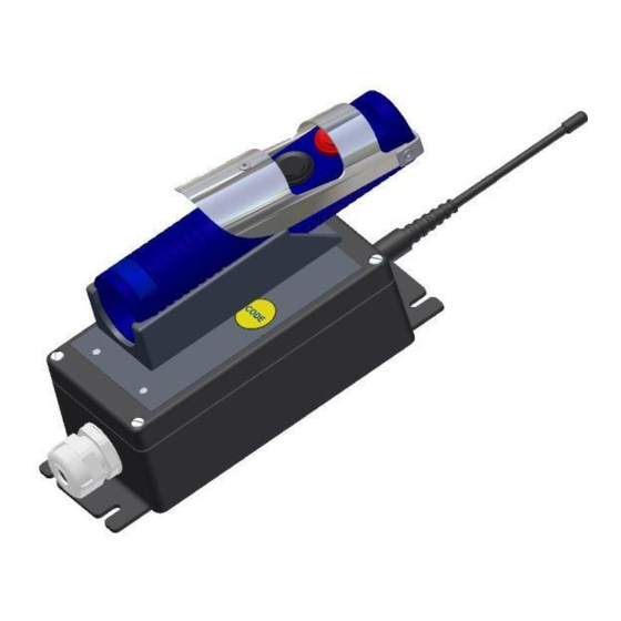
Page 4: Installation
User and Installation Manual, DE212-2S DSD 2. I NSTALLATION NSTALLATION OF THE RECEIVER Figure 2.1 Receiver and Transmitter in the drivers cabin The receiver unit with antenna is normally installed in the drivers cabin, out of Ex defined area. The receiver must have connection to power supply/battery, 12 or 24VDC, and the fuel valve, controlling the filling of the aircraft. -
Page 5: Receiver Unit Connections
User and Installation Manual, DE212-2S DSD ECEIVER ONNECTIONS All connections to the deadman system are made in the receiver unit. Receiver connections HF-module Antenna connection Range adjustment (See note below) Receiver connector P3 Receiver connector P1 (If applicable) 1. Pannic STOP output 1. - Page 6 User and Installation Manual, DE212-2S DSD Connector Functional description Receiver function P1 in receiver Select, SW2 Panic STOP output SW2-1: 2 min. timer ON/OFF ON= timer active, OFF=No timer Timer warning output SW2-2: Extra function simultaneous or not simultaneous operation with the deadman function. ON = simultaneous operation Extra function, for hose reel or pump speed control...
- Page 7 User and Installation Manual, DE212-2S DSD Receiver connections, connector P3: Note that connector P3 is not installed unless programme 02046 and this functions are ordered. Functions installed with receiver programme: 02046 Connector P3 Functional description External override SW2-3 : External The deadman function is active as long as this input is override low, connected to GND...
-
Page 8: Changing The Function Of The Receiver Unit By Sw2
User and Installation Manual, DE212-2S DSD SW2. HANGING THE FUNCTION OF THE RECEIVER UNIT BY From May 2007, a new software, item nr 02017, was introduced in the receiver unit. With this software, the function of the receiver unit can be changed according to operational requirements. -
Page 9: E X Certification
User and Installation Manual, DE212-2S DSD ERTIFICATION The handheld unit, the TX212 transmitter is Ex approved, to verify this, look at the identification label located under the handle. Note that the certification is no longer valid if the TX212 is repaired by an un-authorized workshop, or if the instruction given in this document is not followed. -
Page 10: Operation
Approx. 14 cm long antenna for installation on top of the receiver. OPTIONAL: external antenna with 3m cable for external mounting. • Delta CH300, 115/ 230V mains-powered battery charger for transmitter, OPTIONAL. See section 5.2. RC AS Page 10 of 24... -
Page 11: Functional Description
The battery is charged by the stainless steel contacts at the back side of the transmitter. The transmitter must be charged on the charge station on the receiver front panel, or on a mains battery charger, CH300 delivered by Delta. The charging connections, are protected from discharging of the built-in battery. -
Page 12: Receiver Unit
User and Installation Manual, DE212-2S DSD The LB red LED is active only when the transmitter is activated. By pressing the Stop- button, the battery can be tested during active transmission. The Stop button, or PANNIC button, turns off the functions in the transmitter and sends an active STOP, turning instantly off all the functions activated in the receiver. -
Page 13: Coding The Transmitter And Receiver Units
To keep the classification, and the safety level, the TX212 unit should be inspected regularly . In case of a damage of the TX212, it should be send for repair to Delta RCS or an appointed service station immediately . All services and repair actions of the unit, will be stored at the repair station, and by Delta RCS store. -
Page 14: Battery Recharging
A normal lifetime for a battery is approximately 500 recharging. NOTE: Repair of the TX212 must take place at Delta RCS or by a Delta RCS appointed dealer. Otherwise IECEx certifications is no longer valid. -
Page 15: Replacing The Battery
The battery module 02465 and all replaceable parts of the transmitter, must be original parts delivered by Delta RCS AS. Otherwise the Ex certifications are lost, and the customer has to take all responsibilities. The operator is allowed to change the battery module and nothing else. -
Page 16: Options, Additional Equipment And Spare Parts
User and Installation Manual, DE212-2S DSD 4. O PTIONS ADDITIONAL EQUIPMENT AND SPARE PARTS PTIONS The DE212 is a deadman control system designed for aero plane refuelling trucks and dispensers. Both the receiver and transmitter are controlled by a microprocessor, making it possible to tailor special functions for a customer. -
Page 17: 4.3.1 Receiver Front Unit, Parts Identification
User and Installation Manual, DE212-2S DSD 4.3.1 Receiver front unit, parts identification Range HF module Input voltage fuse Main connector Autofuse 5A adjustment connectors HF module Antenna Connector P3 Main printed circuit # 01854 connector Function select (If applicable) board / PCB # 01852 4.3.2 Transmitter parts identification Battery module connector, P3... -
Page 18: Warranty Conditions
The guaranty ceases 12 months after the delivery date. Delta RCS AS or appointed repair workshop, is bound to repair and replace defect parts in its products, free of charge, in its main workshop during its normal working hours. Packages being sent to and from Delta are in the responsibility of the purchaser, as he is also economically responsible for paying the transportation charges, toll, insurance and other charges related. -
Page 19: Approved Service Stations
User and Installation Manual, DE212-2S DSD PPROVED ERVICE TATIONS Norway Delta RC AS P.O.Box 1065 NO-3204 Sandefjord Phone: +4733448390 E-mail: hello@deltarc.no Germany Henniger Electronics Untere Dorfstrasse 24 DE-38304 Wolfenbüttel Germany Phone: +495331904103 Fax: +495331904115 E-mail: a.henniger@henniger-electronics.de UK and Ireland Aljac Fuelling Components Ltd... -
Page 20: Agents
User and Installation Manual, DE212-2S DSD GENTS Thailand Aviation Enterprise Co. 54/116 Soi3. Baranee Village Klongsam. Klongluang, Pathum Thanee 12120 Bangkok Thailand Phone: +6628327253 Fax: +6625997662 E-mail: aviation_enterprise@yahoo.com France Marco Tech S.A.R.L. Quai Carriet (Montane’) FR-33310 Lormont France Phone: +33557306300 Fax: +33557306301 E-mail: marcotech@free.fr... -
Page 21: Technical Data
User and Installation Manual, DE212-2S DSD 6. T ECHNICAL This equipment complies with the following standards: Europe/EU: ERC 70-03 EN 300-400. USA: FCC 15.249. Japan: STD-T66. It is in accordance to EU’s demands in order to label the equipment with CE. Transmitters are IECEx approved, according to: IECEx: IEC 60079-0 Ed.5 and IEC 60079-11 Ed. - Page 22 User and Installation Manual, DE212-2S DSD Transmitter • Output Power: max. 1mW/0dBm • Antenna: Internal. • Power Supply: 3,6 V NiMH battery, 300mAh. Rechargeable by external contacts. • Charging Constant current charging, 50mA controlled by charging station on receiver front panel. Charging contacts protected against short circuit.
-
Page 23: Dimensions
User and Installation Manual, DE212-2S DSD IMENSIONS Receiver and transmitter unit Note: Dimensions in mm. RC AS Page 23 of 24 ELTA Document 02481... - Page 24 Transmitter unit Note: Dimensions in mm. Delta RC AS reserves the right to make changes without further notice to the product, to improve reliability, functions and design. Delta RC AS does not assume any liability arising out of the application or use of the product if used according to this document.
Need help?
Do you have a question about the DE212-2S GLOBAL DSD and is the answer not in the manual?
Questions and answers