Table of Contents
Advertisement
Quick Links
Advertisement
Table of Contents

Related Manuals for Dahua Technology ANPR


Summary of Contents for Dahua Technology ANPR
- Page 1 ANPR System Installation Guide V1.0.0 ZHEJIANG DAHUA VISION TECHNOLOGY CO., LTD.
- Page 2 Foreword General This installation guide (hereinafter referred to as the "Guide") introduces the structure, installation, wiring, and commissioning of AI enforcement camera system. It is designed to guide engineering technicians, contractors, and more for device installation and commissioning Safety Instructions The following categorized signal words with defined meaning might appear in the Guide.
-
Page 3: Important Safeguards And Warnings
Important Safeguards and Warnings Operation Requirement Do not place or install the device in a place exposed to sunlight or near the heat source. Keep the device away from dampness, dust or soot. Keep the device installed horizontally on the stable place to prevent it from falling. ... - Page 4 Construction Safety Instructions Construction workers must wear protective equipment such as reflective vest to ensure safety during construction. Construction sites must be blocked off and placed with signs. Specific requirements are as follows: Work on city road: Place in sequence work zone warning sign, work zone speed limit sign, ...
-
Page 5: Table Of Contents
Table of Contents Foreword ..............................I Important Safeguards and Warnings ....................... II Table of Contents ............................IV 1 Device List ............................... 5 2 System Structure............................. 6 3 Devices and Accessories ........................7 Devices ............................7 3.1.1 AI Enforcement Camera ....................... 7 3.1.2 Lens ............................ -
Page 6: Device List
Mounting bracket, Bracket 1.1.02.08.11914 PFA150 needs to be purchased separately 1.0.01.09.0237 Edge storage DHI-ITSE0804-G 1.0.01.09.10329 DH-ITSE0400-GN5A- device N5B-D B (optional) DHI-ITARD-024S Radar detector 1.0.01.09.10282 A-ST Multi-target DHI-ITARD-024M 1.2.01.69.10225 ANPR radar Signal detector 1.0.01.09.0129 DH-ITASD-012B... -
Page 7: System Structure
System Structure... -
Page 8: Devices And Accessories
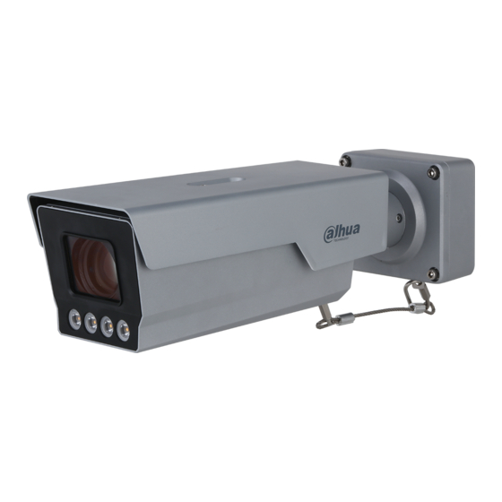
Devices and Accessories Devices 3.1.1 AI Enforcement Camera AI Enforcement Camera_User's Manual_20200806.pdf 3.1.2 Lens Built-in 10.5mm–42mm lens. 3.1.3 Radar DHI-ITARD-024SA-ST radar This radar is an integrated traffic auxiliary product with a high degree of intelligence in the field of intelligent transportation for dynamic detection of moving vehicles. It can detect vehicles of 1 lane. - Page 9 Parameter Description frequency Transmit power 20 dBm Antenna 6.5° (H) × 5.5° (V) beamwidth sampling 25 kHz frequency Work mode Forward direction Number of lane Single lane Detection Vehicle speed (instantaneous speed) information ≥ 95% Capture rate Speed detection ± 1 km/h accuracy Speed detection...
-
Page 10: Edge Storage Device
Detection performance is not influenced by vehicles of adjacent lanes, or vehicles from the front or back side. All-weather and all-time. Detection performance is not influenced by environmental factors such as sunlight, dust, adverse weather, and temperature. High capture rate. - Page 11 Figure 3-2 Edge storage device Table 3-3 Edge storage device parameters Parameter Description Operating system Embedded Linux Operation interface Video input 4-channel network compression HD video input Alarm input 2-channel alarm input Alarm output 2-channel alarm output, relay contact Storage 2 built-in SATA ports (2.5-inch HDD) RS-232 port 2, used for debugging serial port data.
-
Page 12: Accessories
Reset button. Restore default factory settings. How to reset: RESET Press and hold the reset button for at least 10 s when the cameras is running (the power indicator is green), then the system configuration will restore factory default settings. 12 V DC Power interface. -
Page 13: Cable
Figure 3-5 Bracket Table 3-6 Bracket parameters Parameter Description Material Die casting aluminum Mounting Wall-mounted Load bearing 20 kg Supported product DHI-ITABX-018BA protective cover Weight 1.1 kg Length 120 × 103 × 85 mm 3.2.2 Cable Cables used in the Guide are as follows: ... -
Page 14: Air Switch, Power Surge Protector, Ethernet Surge Protector
3.2.5 Air Switch, Power Surge Protector, Ethernet Surge Protector We recommend to using CHNT air switch, DXH06-F power surge protector, and FRX-SL-RJ45 Ethernet surge protector. 3.2.6 Fiber Optical Transceiver and Switch (Optional) We recommend to using industrial-grade switch and HF-500 fiber optical transceiver. -
Page 15: Installation
Installation Installation Diagram Figure 4-1 Installation diagram... -
Page 16: Installation Notes
Installation Notes Traffic pole: Installed at 6 meters high, and 19–20 meters away from the snapshot position. Lens: Adjust lens focal length according to the scenario. Camera: Installed at center of the scenario (over the center of Lane 2). ... -
Page 17: Installing Radar
Side Installation with Bracket Figure 4-3 Side installation Installing Radar This section takes mounting DHI-ITARD-024SA radar for example. Step 1 Mount the radar panel to the radar bracket. Pay attention to the mounting direction of radar panel. The radar bracket is designed with 4 holes that can align with the holes in the panel. -
Page 18: Installing Edge Storage Device
Step 2 Use screws to tighten the radar panel to the radar bracket. See Figure 4-5. Figure 4-5 Install radar (2) Step 3 Mount the radar bracket to PFA162 bracket. See Figure 4-6. Figure 4-6 Install radar (3) Step 4 Mount PFA162 bracket to the traffic pole. - Page 19 Connect the platform to GIGA port through network cable, and connect cameras to switch ports. See Figure 4-7. Figure 4-7 Single segment networking method Dual Segment Networking Method In this method, the camera and the platform are configured in different network segments. The default Ethernet card IP address is 192.168.1.108.
-
Page 20: Wiring
Wiring Wiring Diagram Figure 5-1 Wiring diagram Radar signal cable is only 1.5 meters. In scenario with multiple lanes, pay attention to use extension cord to connect the radar and the camera. Radar should be powered separately, and its power adapter should be placed in wall-mounted or floor-standing cabinet. -
Page 21: Connecting Radar Power Cable
Table 5-1 Wiring camera and radar Radar Cable Camera Cable color Port Yellow Green Brown Figure 5-2 Wiring camera and radar Connecting Radar Power Cable Radar is supplied with 12 V DC power, and its power adapter should be placed in wall-mounted or floor-standing cabinet. -
Page 22: Commissioning
Commissioning Configuring Radar Step 1 Configure radar parameters. Log in to web interface of camera, and then select Setup > ITC > Intelligent > Radar. Figure 6-1 Radar Select Enable Radar, and then you can configure the parameters. Table 6-1 Radar parameter description Parameter Description Enable Radar... -
Page 23: Commissioning Radar
Parameter Description Detect Mode The detection direction of radar. The angle between the directions of the radar beam and the Angle vehicle. You can select the sensitivity of snapshot by radar. The larger Sensitivity the value, the more sensitive the radar. Trigger Snapshot will be triggered when the vehicle speed reaches the Speed... -
Page 24: Commissioning Strobe
Figure 6-3 Commissioning radar Commissioning Strobe Step 1 Check the cable connection of strobe. You can check whether the strobe flashes in the video image (set the shutter speed of camera as 0–3, and gain as 30). If it flashes, then it is properly connected. If not, check the cable connection again. - Page 25 Figure 6-4 Commissioning flashing light...
Need help?
Do you have a question about the ANPR and is the answer not in the manual?
Questions and answers