Table of Contents
Advertisement
Quick Links
Advertisement
Table of Contents

Subscribe to Our Youtube Channel
Related Manuals for Record FlipFlow Twin


Summary of Contents for Record FlipFlow Twin
- Page 1 FlipFlow Twin Translation of the original manual...
- Page 2 Document identification Article nr.: 121-006454269 Version: Publication date: 22/11/2021 Subject to technical modifications Copyright © agtatec ag...
-
Page 3: Table Of Contents
Target groups ............................11 Definition of terms ..........................12 3 Description................................ 13 General Description ..........................13 3.1.1 Capacity of the FlipFlow TWIN ......................13 Product overview ..........................15 Type of installation..........................15 Safety features and controls ......................... 15 3.4.1 BDE-S .............................. 15 3.4.2... - Page 4 Table of contents 5 Inspection and maintenance .......................... 30 General remarks ........................... 30 Cleaning..............................30 6 Malfunctions ..............................31 Perform reset / restart ........................... 31 Examples of errors / alarms ......................... 31 6.2.1 Wrong direction alarm........................31 6.2.2 Technical alarms..........................35 6.2.3 Intrusion alarm ..........................
-
Page 5: Table Of Revisions
Table of revisions Table of revisions Perform reset / restart New chapter ................................ 31 BAL_FF_TWIN_EN_2V3_REC_121-006454269 5 / 38... -
Page 6: Safety
Safety Safety Presentation of warning signs Various symbols are used in this guide for easier understanding: NOTICE Useful advice and information to ensure correct and efficient workflow of the system. IMPORTANT Specific details which are essential for trouble-free operation of the system. IMPORTANT Important details which must be read for proper function of the system. -
Page 7: General Hazards
Safety General hazards The following section lists hazards that can be caused by the system even when used as intended. To reduce the risk of malfunction, damage to property or injury to persons and to avoid dangerous situations, the safety instructions listed here must be observed. The specific safety instructions in the other sections of this manual must also be observed. - Page 8 Safety CAUTION Risk of material damage or injury due to unforeseen opening, closing or turning of the door! a) The door can open, close or turn unexpectedly. This may result in damage to property or injury to persons. ð No persons may be present in the opening area of the system. ð...
-
Page 9: State Of Technology
Safety DANGER Danger to life due to electric current! a) In case of contact with live parts, there is an immediate danger to life due to electric shock. Damage to or removal of the insulation or individual components can be life-threatening. ð... -
Page 10: Spare Parts And Liability
Safety The head protection serves to protect against falling and flying parts and materials. It also protects the head from bumping into hard objects. Protective goggles protect the eyes from flying parts, dust, splinters or splashes. Protective gloves are designed to protect hands from friction, abrasions, punctures or serious injury and from burning caused by contacting hot surfaces. -
Page 11: General Information
General information General information Purpose and use of the instructions These instructions are an integral part of the system and enable efficient and safe handling of the sys- tem. In order to ensure proper functioning, the instructions must be accessible at all times and kept in the immediate area of the system. -
Page 12: Definition Of Terms
General information Definition of terms Term: Explanation: System The term is also used in these instructions as a synonym for the product. Door operators, revolving doors, sliding doors, etc. are re- ferred to as a system. If information in these instructions refers to a specific type, this is shown accordingly in the text. -
Page 13: Description
– FF TWIN 1400 Interpretation principle The FlipFlow TWIN is designed for automatic handling of passenger traffic in and around airports and other security-sensitive buildings. People walk individually through the corridor in only one direction and without the ability to go back in the direction they came from, i.e. in the opposite direction. The FlipFlow also prevents uncontrolled access by people coming from a public area to a security zone or a protected area. - Page 14 In all three cases, however, the average passenger flow per hour is identical. A FlipFlow TWIN can handle around 1500 to 2000 people per hour in FLOW mode. Of course, the throughput rate decreases if a single passenger interrupts the flight in any way.
-
Page 15: Product Overview
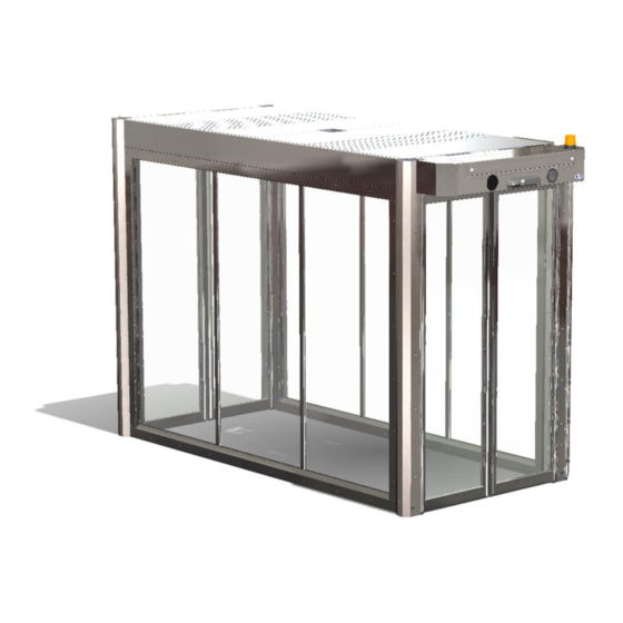
Description Product overview 1 – entrance door 2 – exit door 3 – handrail (option) 4 – protective screen Type of installation Safety features and controls 3.4.1 BDE-S The control panel BDE-S (for the selecting the operating mode) is located in the on the cladding behind the cover of the entrance door. -
Page 16: Emergency Open Push Button
Description 3.4.2 Emergency open push button In the event of a system failure or panic, the emergency escape switch can be operated to bring the FlipFlow into the safety position. FlipFlow-status – Lighting on – Entrance door closed and locked –... -
Page 17: Conduct During Power Failure (Battery Pack Optional)
Description 3.4.6 Conduct during power failure (battery pack optional) In the event of a power failure, the entrance door closes and locks while the exit door unlocks and opens. The FlipFlow remains in this position until power is restored. This mode is only available when the optional battery pack is selected. -
Page 18: Operation
Operation Operation How to operate the BDE-S control panel The BDE-S is a key switch with 5 positions: Simply insert the key into the lock and then turn it until the LED cor- responding to the desired operating mode lights up. Each time the key is turned, another LED lights up. -
Page 19: Closed And Locked Operating Mode
Operation 4.2.2 CLOSED and LOCKED operating mode Also serves as a manual reset Status of the FlipFlow: – Illumination is off. – LED-Strips and pictograms are red. – Doors are closed and locked. If secured, it is prohibited to use the service display. NOTICE Configurable with the service display: a) Option to enable detection in tunnel to open the exit door. -
Page 20: Flow Operating Mode
Operation NOTICE Configurable with the service display: a) Activation / deactivation of the sensors and movement detection. IMPORTANT In this mode, the security level is compromised! If detection in the tunnel is deactivated, it is possible to pass through in both directions without trigger- ing an alarm. -
Page 21: Interlock Operating Mode
Operation – A passenger enters the tunnel, the door closes again (if another passenger arrives, the door stays open). – A passenger arrives in front of the exit door, and the door opens. – The passenger exits the tunnel, the door closes again (if another passenger arrives, the door stays open). - Page 22 Operation Initial state: – Illumination is on. – Entrance door is closed. – Exit door is closed. – LED-Strips are green. – Entrance pictogram is green. If secure, it is not permitted to use the service display . Cycle – A passenger arrives in front of the entrance radar, the door opens.
-
Page 23: Interlock Operating Mode / Auto-Flow
Operation – To increase the flow of persons and to minimize the eventual waiting time, the entrance door opens again, if the exit door is closed and the INTERLOCK is empty. After a short waiting time, the entrance door will close again. If another passenger enters the detection field of the tunnel, the FlipFlow will return to its normal INTERLOCK-Mode. - Page 24 Operation Cycle When passenger flow is low, the FlipFlow operates in INTERLOCK mode as described above. – If the number of passengers exceeds the preset threshold value the FlipFlow changes to FLOW mode and operates as described above. – The flow level is higher than the fixed threshold value the FlipFlow remains in FLOW mode and oper- ates as previously described.
-
Page 25: Cleaning Mode
Operation – The flow drops below the fixed threshold value the FlipFlow switches back to INTERLOCK mode and operates as described above. NOTICE Configurable with the service display: a) Flow and Interlock mode parameters. b) Flow - > Interlock threshold value. c) Interlock - >... -
Page 26: Maintenace Mode
Operation Exiting cleaning mode This mode can exited in two ways: – The service personnel deactivate this mode themselves before the set time expires and the Flip- Flow goes back to the operating mode previously set. – The FlipFlow sends an audible signal indicating that the set time has expired, after a second time delay, the FlipFlow will prepare to close. -
Page 27: Test Mode - Without Alarm Function
Operation 4.2.9 TEST mode – without alarm function This function allows the FlipFlow operating modes to be tested without triggering an alarm (no alarm signal transmitted to the BMS). This function can be activated by turning the rotary button on the con- trol panel. -
Page 28: Emergency Opening
Operation 4.2.11 Emergency opening When this function is activated, the FlipFlow doors open regardless of the status of the safety sensors. This mode is activated in case of fire or emergency by a remote switch in the building management system. This switch is provided by the customer and will interrupt the con- nection between pin 3 and pin 4 on PM11 on the circuit board of each tunnel. -
Page 29: Example Of The Antipassback Function
Operation 4.2.15 Example of the Antipassback function A person crosses the exit door threshold in the opposite direction, an alarm is set off and the entrance door closes BAL_FF_TWIN_EN_2V3_REC_121-006454269 29 / 38... -
Page 30: Inspection And Maintenance
Inspection and maintenance Inspection and maintenance Regular inspection and maintenance of the system by trained and authorized personal from the man- ufacturer, is the best guarantee for long life and trouble-free secure operation. These control and maintenance operations are required at regular intervals, following the manufac- turer's instructions and the relevant legal requirements. -
Page 31: Malfunctions
Malfunctions Malfunctions Perform reset / restart NOTICE Some faults can remedied by resetting / restarting the control unit. – Set the key switch to the CLOSED and LOCKED op- erating mode. The system moves to the home position and performs a reset. - Page 32 Malfunctions A person or object remains under the exit door or in zone 3, the exit door closes. NOTICE Configurable with the Service Display: a) Setting all timers relevant to triggering the alarms. A person or object remains under the entrance door or in zone 2a, the entrance door opens. A person or object remains under the exit door or in zone 3, the exit door opens.
- Page 33 Malfunctions The entrance and exit doors are no longer in their end positions. – The entrance door does not open (or close) when it – The exit door does not open (or close) when it should. should. NOTICE Configurable with the Service Display: a) Setting all timers relevant to triggering the alarms With this option, entrance door closed, a presence detected on the floor.
- Page 34 Malfunctions NOTICE Configurable with the Service Display: a) Activation/deactivation of floor detection in FLOW mode With this option, entrance door closed, a presence is detected on the wall or ceiling. With this option, activating of the emergency open button generates a technical alarm. NOTICE Configurable with the Service Display: a) Setting all timers relevant to triggering the alarms.
-
Page 35: Technical Alarms
Malfunctions 6.2.2 Technical alarms This alarm is triggered if a traffic flow interruption has lasted too long or if a technical error has been detected. A reset is required to deactivate this alarm. A ringtone sounds at regular intervals as a reminder. 6.2.3 Intrusion alarm This alarm is triggered when the wrong direction is de-... -
Page 36: Throw-In Alarm (Optional)
Malfunctions NOTICE In order to limit the number of false intrusion alarms when the wrong direction detected by the cameras and the entrance door is not closed, the FlipFlow will measure the time it takes to close the entrance door and compares it with referenced time: If the closure time is less than the reference time, an anti-pass-back alarm triggered. -
Page 37: Taking Out Of Service And Disposal
Taking out of service and disposal Taking out of service and disposal Decommissioning When shutting down or taking out of service, the system is disconnected from the mains supply and any existing battery is unplugged. NOTICE After each temporary shutdown a new commissioning must be carried out. Dismantling and disposal IMPORTANT All machine parts must be sorted by type of material and disposed of according to... - Page 38 Denmark www.record-danmark.dk España www.record.es France www.record.fr Great Britain www.recorduk.co.uk Malaysia www.recorddoors.my Polska pl.record.global Schweiz www.record.ch Sverige www.record.se Türkiye tr.record.global United States www.recorddoors.com record global export www.record.global record Group www.record.group Subject to technical modifications Copyright © agtatec ag No. 121-006454269...
Need help?
Do you have a question about the FlipFlow Twin and is the answer not in the manual?
Questions and answers