Sign In
Upload
Manuals
Brands
Juniper Manuals
Network Router
M320
Juniper M320 Multiservice Edge Router Manuals
Manuals and User Guides for Juniper M320 Multiservice Edge Router. We have
4
Juniper M320 Multiservice Edge Router manuals available for free PDF download: Hardware Manual, Quick Start Manual, Datasheet
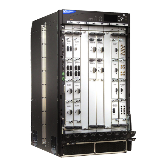
Juniper M320 Hardware Manual (392 pages)
Multiservice Edge Router
Brand:
Juniper
| Category:
Network Router
| Size: 9 MB
Table of Contents
Table of Contents
3
List of Tables
19
About the Documentation
23
Documentation and Release Notes
23
Documentation Conventions
23
Supported Platforms
23
Table 1: Notice Icons
24
Table 2: Text and Syntax Conventions
24
Documentation Feedback
25
About the Documentation
25
Opening a Case with JTAC
26
Requesting Technical Support
26
Self-Help Online Tools and Resources
26
Overview
29
Chassis Components and Descriptions
29
Cooling System Components and Descriptions
29
Host Subsystem Components and Descriptions
29
Line Card Components and Descriptions
29
Power System Components and Descriptions
29
Switch Fabric Components and Descriptions
29
Chapter 1 System Overview
31
M320 Router Description
31
M320 Component Redundancy
32
Chapter 2 M320 Router Release Notes
33
M320 Router Release Notes
33
Errata with the M320 Router Documentation
33
Outstanding Issues with the M320 Router
33
Chassis Components and Descriptions
35
Chapter 3 Chassis Components and Descriptions
35
M320 Chassis Description
35
Figure 1: Front View of a Fully Configured Router Chassis
36
Figure 2: Rear View of a Fully Configured AC-Powered Router Chassis
37
M320 Midplane Description
38
Figure 3: Rear View of a Fully Configured DC-Powered Router Chassis
38
Figure 4: Midplane
39
Chassis Components and Descriptions
39
M320 Fuses
40
M320 Cable Management System Description
40
Figure 5: Cable Management System
40
M320 Connector Interface Panel (CIP) Description
41
CIP Components
41
Figure 6: CIP
42
Routing Engine Ports
42
Alarm Relay Contacts
43
M320 Craft Interface Description
43
Figure 7: Front Panel of the Craft Interface
43
M320 Craft Interface Alarm Leds and ACO/LT Button
44
M320 Craft Interface LED Display and Navigation Buttons
44
Table 3: Alarm Leds and Alarm Cutoff/Lamp Test Button
44
M320 Connector Interface Panel (CIP) Description
44
M320 Craft Interface Description
44
Figure 8: LED Display in Idle Mode
45
Figure 9: LED Display in Alarm Mode
45
M320 Craft Interface Host Subsystem Leds
46
M320 Craft Interface FPC Leds and Online/Offline Buttons
46
Table 4: M320 Host Subsystem Leds
46
Table 5: FPC Leds
46
M320 Craft Interface Power Supply Leds
47
M320 Craft Interface SIB Leds
47
Table 6: Power Supply Leds on the Craft Interface
47
Table 7: SIB Leds on the Craft Interface
47
Chapter 4 Cooling System Components and Descriptions
49
M320 Cooling System Description
49
Figure 10: Airflow through the Chassis
49
Components
50
Chapter 5 Host Subsystem Components and Descriptions
51
M320 Host Subsystem Description
51
M320 Routing Engine Description
52
M320 Routing Engine 600 Description
53
Figure 11: Routing Engine 1600
54
M320 Routing Engine 1600 Description
54
M320 Routing Engine 2000 Description
55
Figure 12: Routing Engine 2000
56
M320 RE-A-1800 Routing Engine Description
56
Routing Engine Components
56
Figure 13: RE-A-1800 Routing Engine
57
Figure 14: RE-A-1800X2 Routing Engine
57
Figure 15: USB Memory Device in an Routing Engine
58
Routing Engine Boot Sequence
58
RE-A-1800 Routing Engine Leds
59
Routing Engine Specifications
59
Table 8: Routing Engine Leds
59
Table 9: Routing Engine Specifications
59
Table 10: End-Of-Life Routing Engine Specifications
61
M7I Routing Engines
62
Supported Routing Engines by Router
62
M10I Routing Engines
63
M40E Routing Engines
63
Table 11: M7I Routing Engines
63
Table 12: M10I Routing Engines
63
Table 13: M40E Routing Engines
63
M120 Routing Engines
64
M320 Routing Engines
64
Table 14: M120 Routing Engines
64
Table 15: M320 Routing Engines
64
MX104 Routing Engines
65
MX240 Routing Engines
65
Table 16: MX104 Routing Engines
65
Table 17: MX240 Routing Engines
65
MX480 Routing Engines
66
Table 18: MX480 Routing Engines
66
MX2010 Routing Engines
67
MX960 Routing Engines
67
Table 19: MX960 Routing Engines
67
Table 20: MX2010 Routing Engines
67
MX2020 Routing Engines
68
PTX3000 Routing Engines
68
PTX5000 Routing Engines
68
Table 21: MX2020 Routing Engines
68
Table 22: PTX3000 Routing Engines
68
Table 23: PTX5000 Routing Engines
68
T320 Routing Engines
69
T640 Routing Engines
69
Table 24: T320 Routing Engines
69
Table 25: T640 Routing Engines
69
T1600 Routing Engines
70
Table 26: T1600 Routing Engines
70
T4000 Routing Engines
71
Table 27: T4000 Routing Engines
71
Table 28: TX Matrix Routing Engines
72
Table 29: TX Matrix Plus Routing Engines
72
TX Matrix Plus (with 3D Sibs) Routing Engines
72
TX Matrix Plus Routing Engines
72
TX Matrix Routing Engines
72
Figure 16: CB
73
M320 Control Board (CB) Description
73
Table 30: Routing Engines on TX Matrix Plus with 3D Sibs
73
M320 Control Board (CB) Leds
74
Table 31: M320 CB Leds
74
Chapter 6 Line Card Components and Descriptions
77
M320 Flexible PIC Concentrator (FPC) Description
77
Figure 17: FPC Installed in Router Chassis
78
Figure 18: FPC1, FPC2, and FPC3 for the M320 Router
79
Line Card Components and Descriptions
79
Figure 19: Enhanced II FPC1, FPC2, and FPC3 for the M320 Router
80
Figure 20: Enhanced III FPC1, FPC2, and FPC3 for the M320 Router
80
M320 FPC Terminology
81
M320 Fpcs Supported
81
Figure 21: FPC Edges
81
M320 PIC Description
82
Table 32: Fpcs Supported by the M320 Router
82
M320 Pics Supported
83
Table 33: ATM IQ Pics Supported by the M320 Router
83
Table 34: ATM2 IQ Pics Supported by the M320 Router
84
Table 35: Channelized Pics Supported by the M320 Router
84
Table 36: Channelized IQ Pics Supported by the M320 Router
85
Table 37: Channelized IQE Pics Supported by the M320 Router
85
Table 38: Circuit Emulation Pics Supported by the M320 Router
86
Table 39: DS3, E1, E3, and T1 Pics Supported by the M320 Router
86
Table 40: EIA-530 PIC Supported by the M320 Router
87
Table 41: Fast Ethernet Pics Supported by the M320 Router
87
Table 42: Gigabit Ethernet Pics Supported by the M320 Router
88
Table 43: 10-Gigabit Ethernet Pics Supported by the M320 Router
90
Table 44: Service Pics Supported by the M320 Router
90
Table 45: SONET/SDH Pics Supported by the M320 Router
91
M320 End-Of-Life Pics Supported
92
Table 46: End-Of-Life Pics Supported in the M320 Router
92
M320 PIC Combination Limitations
94
M320 PIC/FPC Compatibility
94
PIC/FPC Compatibility (Type 1 Fpcs and Type 1 Pics)
95
Table 47: M320 PIC/FPC Compatibility Type 1
96
PIC/FPC Compatibility (Type 2 Fpcs and Type 2 Pics)
98
PIC/FPC Compatibility (Type 3 Fpcs and Type 3 Pics)
99
Table 48: M320 PIC/FPC Compatibility Type 2
99
Table 49: M320 PIC/FPC Compatibility Type 3
100
Chapter 7 Power System Components and Descriptions
101
M320 Power System Description
101
M320 AC Power Supplies Description
101
Figure 22: AC Power Supply
102
Components Powered by each Power Supply Slot
103
Isolated DC Power Supply
103
Nonisolated DC Power Supply
103
Table 50: Components Powered by each DC Power Supply Slot
103
DC Power Supply Load Sharing and Fault Tolerance
104
M320 DC Power Supplies Description
102
M320 Power Supply Leds
104
Table 51: Power Supply LED
104
Chapter 8 Switch Fabric Components and Descriptions
107
M320 Performance for Different SIB Configurations
108
Table 52: Performance Per SIB/FPC Configuration
108
M320 SIB Leds
109
Table 53: SIB Leds
109
Site Planning, Preparation, and Specifications
111
AC Power Specifications
111
DC Power Specifications
111
Preparation Overview
113
Chapter 9 Preparation Overview
113
Table 54: Site Preparation Checklist
113
M320 Router Physical Specifications
114
Rack
114
Table 55: M320 Physical Specifications
114
Preparation Overview
115
Rack Requirements for the M320 Router
115
Figure 24: Typical Open-Frame Rack
116
M320 Cabinet Size and Clearance Requirements
116
Table 56: Cabinet Clearance Requirements
117
M320 Cabinet Airflow Requirements
118
Figure 25: Airflow Baffle Template
119
M320 Clearance Requirements
119
Figure 26: Chassis Dimensions and Clearance Requirements
120
Figure 27: Typical Open-Frame Rack
121
M320 Environmental Specifications
121
Table 57: Router Environmental Specifications
121
Figure 28: DC Power and Grounding Cable Lug
122
M320 Chassis Grounding Cable and Lug Specifications
122
Site Electrical Wiring Guidelines for Juniper Networks Devices
123
Distance Limitations for Signaling
123
Electromagnetic Compatibility
123
Radio Frequency Interference
123
M320 Power Requirements
124
Table 58: Component Power Requirements
124
M320 RJ-48 Connector Pinouts for the Control Board External Clock Inputs
126
Table 59: RJ-48 Connector Pinouts
126
M320 Fuse Specifications
127
Table 60: Fuse Specifications
127
Chapter 10 AC Power Specifications
129
M320 AC Power Electrical Specifications
129
Table 61: AC Power Electrical Specifications
129
M320 AC Power Cord Specifications
130
Figure 29: AC Plug Types
131
Table 62: AC Power Cord Specifications
131
Chapter 11 DC Power Specifications
133
M320 DC Power Electrical Specifications
133
DC Power System Electrical Specifications
133
Table 63: DC Power System Electrical Specifications
133
Isolated DC Power Supply Electrical Specifications
134
Nonisolated DC Power Supply Electrical Specifications
134
Table 64: Nonisolated DC Power Supply Electrical Specifications
134
Table 65: Isolated DC Power Supply Electrical Specifications
134
Figure 30: DC Power Cable Lug
135
M320 DC Power Cable Specifications
135
Figure 31: Typical DC Source Cabling to the Router
136
Table 66: DC Power Cable Specifications
136
DC Power Circuit Breaker for M320 Routers
137
M320 DC Power Distribution
137
Chapter 12 Network Cable and Transceiver Planning
139
Understanding Fiber-Optic Cable Signal Loss, Attenuation, and Dispersion
139
Attenuation and Dispersion in Fiber-Optic Cable
139
Signal Loss in Multimode and Single-Mode Fiber-Optic Cable
139
Calculating Power Budget and Power Margin for Fiber-Optic Cables
140
Calculating Power Budget for Fiber-Optic Cable
140
Calculating Power Margin for Fiber-Optic Cable
141
Table 67: Estimated Values for Factors Causing Link Loss
141
Chapter 13 Management Cable and Transceiver Specifications and Pinouts
143
M320 Routing Engine Interface Cable and Wire Specifications
143
Table 68: Cable and Wire Specifications for Routing Engine Management and
143
M320 RJ-45 Connector Pinouts for the Routing Engine ETHERNET Port
144
Ports
144
Table 69: RJ-45 Connector Pinouts
144
Table 70: DB-9 Connector Pinouts
144
Initial Installation and Configuration
147
Connecting the M320 to External Devices
147
Connecting the M320 to Ground
147
Installing the M320 with a Mechanical Lift
147
Installing the M320 Without a Mechanical Lift
147
Installing the Mounting Hardware
147
Providing Power to the M320
147
Unpacking the M320
147
Chapter 14 Installation Overview
149
M320 Router Installation Summary
149
Chapter 15 Unpacking the M320
151
Tools and Parts Required to Unpack the M320 Router
151
Unpacking the M320 Router
151
Figure 32: Contents of the Shipping Crate
152
Verifying the M320 Router Parts Received
153
Table 71: M320 Router Parts List for a Fully Configured Router
153
Table 72: M320 Router Accessory Box Parts List
154
Chapter 16 Installing the Mounting Hardware
155
Installing the M320 Mounting Hardware for a Four-Post Rack or Cabinet
155
Cabinets
155
Installing Cage Nuts (if Needed) for M320 Four-Post Racks or Cabinets
155
Table 73: Four-Post or Cabinet Rack Mounting Hole Locations
155
Cabinets
156
Cabinets
157
Figure 33: Installing the Mounting Hardware for a Four-Post Rack or Cabinet
157
Racks or Cabinets
157
Removing the Adjustable Center-Mounting Brackets for M320 Four-Post
157
Installing the M320 Mounting Hardware for Open-Frame Racks
158
Figure 34: Center-Mounting Bracket Removal
158
Installing Cage Nuts (if Needed) for M320 Open Frame Racks
159
Moving the Adjustable Center-Mounting Brackets for M320 Open-Frame
159
Racks
159
Table 74: Open-Frame Rack Mounting Hole Locations
159
Figure 35: Installing the Mounting Hardware for a Center-Mount Open-Frame
160
Installing the Large Mounting Shelf for the M320 Open-Frame Racks
160
Installing the Small Mounting Shelf for the M320 Open-Frame Racks
160
Figure 36: Center-Mounting Bracket Removal
161
Chapter 17 Installing the M320 with a Mechanical Lift
163
Overview of Installing the M320 Chassis Using a Mechanical Lift
163
Tools Required to Install the M320 Chassis Using a Mechanical Lift
164
Installing the M320 Chassis Using a Mechanical Lift
164
Attaching the Installation Handle to the M320 Chassis
164
Figure 37: Removing an M320 Power Supply before Installing the Installation
165
Figure 38: Attaching the M320 Installation Handle
165
Mounting the M320 Chassis Using a Mechanical Lift
166
Figure 39: Installing the M320 Router in the Rack
167
Supplies
167
Installing the M320 Cable Guards
168
Figure 40: Reinstalling an M320 Power Supply
168
Figure 41: Installing the M320 Cable Guards
169
Chapter 18 Installing the M320 Without a Mechanical Lift
171
Lift
171
Removing M320 Components from the Chassis
171
Figure 42: Removing a Power Supply before Installing the Router
172
Removing the M320 Power Supplies
172
Figure 43: Removing a SIB
173
Removing the M320 Sibs
173
Figure 44: Removing a CB
174
Removing the M320 Cbs
174
Removing the M320 Rear Fan Tray
174
Figure 45: Removing the Rear Fan Tray
175
Removing the M320 Cable Management System
176
Removing the M320 Front Fan Trays
176
Removing the M320 Fpcs
177
Figure 46: Removing a Front Fan Tray
177
Figure 47: Removing an FPC
178
Figure 48: Attaching the Installation Handle
179
Installing the M320 Chassis in the Rack Manually
179
Figure 49: Installing the Router in the Rack
181
Figure 50: Reinstalling the Rear Fan Tray
182
Reinstalling an M320 Rear Fan Tray
182
Figure 51: Reinstalling a CB
183
Reinstalling the M320 Cbs
183
Reinstalling the M320 Sibs
183
Figure 52: Reinstalling a SIB
184
Reinstalling the M320 Power Supplies
184
Figure 53: Reinstalling a Power Supply
185
Reinstalling the M320 Fpcs
185
Figure 54: Reinstalling an FPC
186
Reinstalling M320 Front Fan Trays
186
Reinstalling the M320 Cable Management System
187
Reinstalling M320 Components in the Chassis
181
Figure 55: Reinstalling a Front Fan Tray
187
Installing the M320 Cable Guards
187
Figure 56: Installing the M320 Cable Guards
188
Chapter 19 Connecting the M320 to Ground
189
Figure 57: Grounding Lug
189
Tools and Parts Required to Ground the M320 Router
189
Chapter 20 Connecting the M320 to External Devices
191
Tools and Parts Required for M320 Router Connections
191
Devices
192
Figure 58: Routing Engine Management Ports and Alarm Relay Contacts
192
Connecting the M320 Router to a Management Console or Auxiliary Device
193
Connecting the M320 Router to a Network for Out-Of-Band Management
194
Figure 59: Console and Auxiliary Serial Port Connector
194
Figure 60: Console and Auxiliary Ports on the CIP
194
Figure 61: Routing Engine Ethernet Cable Connector
195
Figure 62: ETHERNET Port on the CIP
195
Connecting the M320 Router to an External Alarm-Reporting Device
196
Connecting the M320 Router to an External Clocking Device
196
Connecting PIC Cables to the M320 Router
197
Figure 63: Attaching Cable to a PIC
198
Figure 64: Installing the Cable Cover
199
Chapter 21 Providing Power to the M320
201
Connecting Power to a DC-Powered M320 Router
202
Figure 65: Connecting AC Power to the M320 Router
202
Figure 66: Connecting DC Power to the M320 Router
204
Powering on the M320 Router
204
Powering off the M320 Router
206
Chapter 22 Configuring the Junos os Software
207
Initially Configuring the M320 Router
207
Installing and Replacing Components
211
Replacing Chassis Components
211
Replacing Cooling System Components
211
Replacing Power System Components
211
M320 Field Replaceable Units
213
Figure 23: SIB-M
107
M320 SIB Description
107
M320 Site Preparation Checklist Requirements
113
Connecting the M320 Router Grounding Cable
189
Connecting Power to an AC-Powered M320 Router
201
Chapter 23 Overview of Installing and Replacing Components
213
Overview of Installing and Replacing Components
213
Table 75: Field-Replaceable Units
214
Table 76: Tools and Parts Required
214
Tools and Parts Required to Replace the M320 Hardware Components
214
Chapter 24 Replacing Chassis Components
217
Replacing the M320 CIP
217
Removing an M320 CIP
217
Figure 67: Removing the CIP
218
Installing an M320 CIP
218
Figure 68: Installing a CIP
219
Replacing the M320 Alarm Relay Wires
220
Replacing an M320 Management Ethernet Cable
220
Figure 69: Ethernet Cable Connectors
221
Replacing an M320 Console or Auxiliary Cable
222
Removing an M320 Console or Auxiliary Cable
222
Figure 70: Routing Engine Console or Auxiliary Cable
223
Installing an M320 Console or Auxiliary Cable
223
Figure 71: Routing Engine Console or Auxiliary Cable
224
Replacing an M320 Craft Interface
225
Figure 72: Removing the Craft Interface
225
Removing an M320 Craft Interface
225
Figure 73: Installing the Craft Interface
226
Installing an M320 Craft Interface
226
Replacing an M320 Fuse
227
Figure 74: Fuses in the Midplane
229
Chapter 25 Replacing Cooling System Components
231
Replacing an M320 Air Filter
231
Removing an M320 Front Air Filter
231
Figure 75: Removing the Front Air Filter
232
Figure 76: Replacing the Front Filter Element
232
Installing an M320 Front Air Filter
232
Figure 77: Installing the Front Air Filter
233
Removing an M320 Rear Air Filter
233
Figure 78: Removing the Rear Air Filter
234
Figure 79: Removing the Rear Air Filter Element
235
Installing an M320 Rear Air Filter
235
Replacing an M320 Fan Tray
236
Figure 80: Installing the Rear Air Filter
236
Removing an M320 Front Fan Tray
236
Figure 81: Removing a Front Fan Tray
237
Figure 82: Installing a Front Fan Tray
238
Installing an M320 Front Fan Tray
238
Removing an M320 Rear Fan Tray
238
Figure 83: Removing the Rear Fan Tray
239
Installing an M320 Rear Fan Tray
239
Figure 84: Installing a Rear Fan Tray
240
Chapter 26 Replacing Host Subsystem Components
241
Taking the M320 Host Subsystem Offline
241
Table 77: Effect of Taking the Host Subsystem Offline
241
Replacing Host Subsystem Components
243
Removing an M320 Routing Engine
244
Replacing an M320 Routing Engine
244
Figure 85: Removing a Routing Engine
245
Installing an M320 Routing Engine
245
Figure 86: Installing a Routing Engine
246
Figure 87: RE-A-1800 Routing Engine SSD Slots
246
Replacing a Solid-State Disk on an M320 RE-A-1800 Routing Engine
246
Engine
247
Inserting or Removing a PC Card from an M320 Routing Engine
247
Installing an Solid-State Disk on an M320 RE-A-1800 Routing Engine
247
Figure 88: Installing a PC Card
248
Inserting a PC Card into an M320 Routing Engine
248
Figure 89: Removing a PC Card
249
Removing an M320 PC Card
249
Replacing a DIMM Module in an M320 Routing Engine
249
Installing an M320 DIMM Module
250
Removing an M320 DIMM Module
250
Figure 90: Installing the DIMM Module
251
Removing an M320 Control Board
251
Replacing an M320 Control Board
251
Figure 91: Removing a CB
252
Figure 92: Installing a CB
253
Installing an M320 Control Board
253
Chapter 27 Replacing Line Card Components
255
Replacing an M320 FPC
255
Removing an M320 FPC
255
Figure 93: Removing an FPC
257
Installing an M320 FPC
258
Figure 94: Installing an FPC
260
Figure 95: Connecting Fiber-Optic Cable to a PIC
261
Removing an M320 PIC
261
Replacing an M320 PIC
261
Figure 96: Removing a PIC
263
Installing an M320 PIC
263
Figure 97: Installing a PIC
265
Replacing M320 PIC Cables
265
Installing an M320 PIC Cable
266
Removing an M320 PIC Cable
266
Figure 98: Connecting Fiber-Optic Cable to a PIC
268
Replacing an M320 SFP
268
Figure 99: Small Form-Factor Pluggable (SFP)
269
Removing an M320 SFP
269
Installing an M320 SFP
270
Removing an M320 XENPAK Module
271
Replacing an M320 XENPAK Module
271
Figure 100: Removing a XENPAK Module
272
Installing an M320 XENPAK Module
273
Figure 101: Installing a XENPAK Module
274
Replacing Line Card Components
257
Chapter 28 Replacing Power System Components
275
Replacing an M320 AC Power Supply
275
Removing an M320 AC Power Supply
275
Figure 102: Removing an AC Power Supply
276
Figure 103: Rear of the Power Supply Showing Midplane Connector
276
Installing an M320 AC Power Supply
276
Figure 104: Installing an AC Power Supply
277
Replacing an M320 DC Power Supply
278
Removing an M320 DC Power Supply
278
Figure 105: Disconnecting Power Cables from the DC Power Supply
279
Figure 106: Removing a DC Power Supply
280
Installing an M320 DC Power Supply
280
Figure 107: Installing a DC Power Supply
281
Replacing an M320 AC Power Supply Cord
282
Figure 108: Connecting Power Cables to the DC Power Supply
282
Replacing an M320 DC Power Supply Cable
283
Figure 109: Disconnecting or Connecting a Power Cable from a DC Power Supply
285
Chapter 29 Replacing Switch Fabric Components
287
Replacing an M320 SIB
287
Removing an M320 SIB
287
Figure 110: Removing a SIB
288
Installing an M320 SIB
288
Figure 111: Installing a SIB
289
Part 5 Maintaining the Chassis and Components
291
Chapter 30 Routine Maintenance Procedures
293
Routine Maintenance Procedures for the M320 Router
293
Chapter 31 Maintaining Components and Cables
295
Tools and Parts Required to Maintain the M320 Hardware Components
295
Maintaining the M320 Air Filters
295
Maintaining the M320 Fan Trays
296
Maintaining the M320 Host Subsystem
297
Maintaining M320 Fpcs
298
Holding and Storing M320 Fpcs
300
Holding M320 Fpcs
300
Figure 112: Do Not Grasp the Connector Edge
301
Figure 113: Do Not Carry an FPC with Only One Hand
301
Figure 114: Do Not Rest the FPC on an Edge
302
Figure 115: Holding an FPC Vertically
303
Storing M320 Fpcs
303
Maintaining M320 Pics and PIC Cables
304
Figure 116: Do Not Stack Fpcs
304
Maintaining the M320 Power Supplies
306
Maintaining the M320 Sibs
307
Part 6 Troubleshooting Hardware
309
Troubleshooting Hardware
309
Chapter 32 Troubleshooting Components
311
M320 Troubleshooting Resources Overview
311
M320 LED Overview
312
Component Leds
312
Craft Interface Leds
312
M320 Chassis and Interface Alarm Messages
313
Table 78: M320 Chassis Alarm Messages
313
Table 79: SONET/SDH Interface Alarm Messages
314
Troubleshooting the M320 Cooling System
315
Figure 117: Airflow through the Chassis
316
Troubleshooting the M320 Fpcs
317
Troubleshooting the M320 Fuses
318
Figure 118: Fuses in the Midplane
318
Troubleshooting the M320 Pics
319
Troubleshooting the M320 Power System
320
Components
321
Contacting Customer Support and Returning the Chassis or Components
323
Chapter 33 Contacting Customer Support
325
Chapter 34 Locating Component Serial Numbers
327
Locating M320 Component Serial Numbers Using the CLI
327
Locating the M320 Chassis Serial Number Label
328
Locating the M320 CIP Serial Number Label
328
Figure 119: Serial Number ID Label
328
Figure 120: M320 Chassis Serial Number Label
328
Locating the M320 Craft Interface Serial Number Label
329
Locating the M320 Routing Engine Serial Number Label
329
Figure 121: CIP Serial Number Label
329
Figure 122: Craft Interface Serial Number Label
329
Locating the M320 CB Serial Number Label
330
Locating the M320 FPC Serial Number Label
330
Figure 123: Routing Engine Serial Number Label
330
Figure 124: CB Serial Number Label
330
Locating the M320 PIC Serial Number Label
331
Figure 125: FPC Serial Number Label
331
Locating the M320 Power Supply Serial Number Labels
332
Figure 126: PIC Serial Number Label
332
Figure 127: AC Power Supply Serial Number Label
333
Figure 128: DC Power Supply Serial Number Label
333
Locating the M320 SIB Serial Number Label
334
Figure 129: SIB Serial Number Label
334
Chapter 35 Packing and Returning Components
335
Returning a Hardware Component to Juniper Networks, Inc
335
Tools and Parts Required to Remove Components from an M320 Router
336
Packing the M320 Router for Shipment
336
Packing M320 Router Components for Shipment
338
Safety and Compliance Information
339
Chapter 36 General Safety Guidelines and Warnings
341
Definition of Safety Warning Levels
341
General Safety Guidelines for Juniper Networks Devices
343
General Safety Warnings for Juniper Networks Devices
344
Qualified Personnel Warning
344
Restricted Access Area Warning
344
M320 in Case of an Electrical Accident
346
Preventing Electrostatic Discharge Damage to an M320 Router
346
Chapter 37 Fire Safety Requirements
349
Fire Safety Requirements for Juniper Networks Devices
349
Fire Suppression
349
Fire Suppression Equipment
349
General Fire Safety Requirements
349
Chapter 38 Installation Safety Guidelines and Warnings
351
M320 Installation Safety Guidelines
351
M320 Chassis Lifting Guidelines
351
M320 General Installation Safety Guidelines
351
Installation Safety Warnings for Juniper Networks Devices
352
Installation Instructions Warning
352
Intra-Building Ports Warning
352
Rack-Mounting Requirements and Warnings
353
Ramp Warning
356
Chapter 39 Laser and LED Safety Guidelines and Warnings
359
M320 General Laser Safety Guidelines
359
Laser Safety Warnings for Juniper Networks Devices
359
Class 1 Laser Product Warning
360
Class 1 LED Product Warning
360
Laser Beam Warning
361
Radiation from Open Port Apertures Warning
361
Chapter 40 Maintenance and Operational Safety Guidelines and Warnings
363
Maintenance and Operational Safety Warnings for Juniper Networks Devices
363
Battery Handling Warning
363
Jewelry Removal Warning
364
Lightning Activity Warning
365
Operating Temperature Warning
366
Product Disposal Warning
367
Chapter 41 Electrical Safety Guidelines and Warnings
369
General Electrical Safety Warnings for Juniper Networks Devices
369
Grounded Equipment Warning
369
Grounding Requirements and Warning
370
Midplane Energy Hazard Warning
371
Multiple Power Supplies Disconnection Warning
371
Power Disconnection Warning
372
Devices
373
M320 AC Power Electrical Safety Guidelines
373
M320 AC Power Electrical Safety Warning
374
M320 DC Power Electrical Safety Guidelines
374
DC Power Electrical Safety Warnings for Juniper Networks Devices
375
DC Power Copper Conductors Warning
375
DC Power Disconnection Warning
376
DC Power Wiring Terminations Warning
377
Chapter 42 Agency Approvals and Compliance Statements
379
Compliance Statements for EMC Requirements for Juniper Networks Devices
380
M320 Compliance Statements for Acoustic Noise
382
Part 9 Index
383
Index
385
M320 Compliance Statements for Nebs
382
Advertisement
Juniper M320 Hardware Manual (320 pages)
Multiservice Edge Router
Brand:
Juniper
| Category:
Wireless Router
| Size: 10 MB
Table of Contents
Table of Contents
7
About the Documentation
21
Junos os Documentation and Release Notes
21
Objectives
21
Audience
22
Documentation Conventions
22
Table 1: Notice Icons
22
Table 2: Text and Syntax Conventions
22
About the Documentation
23
Documentation Feedback
23
Requesting Technical Support
24
Self-Help Online Tools and Resources
24
Opening a Case with JTAC
25
Chapter 7 Installing the M320 Router Without a Mechanical Lift
27
Chapter 8 Connecting the M320 Router
27
Part 1 M320 Multiservice Edge Router Overview
27
M320 Router Description
29
M320 Router Overview
29
Chapter 2 M320 Hardware Components
31
M320 Component Redundancy
31
M320 Chassis Description
32
Chapter 2 M320 Hardware Components
33
Figure 1: Front View of a Fully Configured Router Chassis
33
Figure 2: Rear View of a Fully Configured AC-Powered Router Chassis
34
Chapter 2 M320 Hardware Components
35
Figure 3: Rear View of a Fully Configured DC-Powered Router Chassis
35
M320 Midplane Description
35
Figure 4: Midplane
36
M320 Flexible PIC Concentrator (FPC) Description
37
Figure 5: FPC Installed in Router Chassis
38
Figure 6: FPC1, FPC2, and FPC3 for the M320 Router
39
Figure 7: Enhanced II FPC1, FPC2, and FPC3 for the M320 Router
39
Figure 8: Enhanced III FPC1, FPC2, and FPC3 for the M320 Router
40
M320 Fpcs Supported
40
Table 3: Fpcs Supported by the M320 Router
40
M320 PIC Description
41
Figure 9: SIB-M
42
M320 SIB Description
42
M320 Switch Interface Board (SIB) Overview
42
Table 4: SIB Leds
42
M320 Performance for Different SIB Configurations
43
Table 5: Performance Per SIB/FPC Configuration
43
M320 Host Subsystem Description
44
M320 Host Subsystem Overview
44
M320 Routing Engine Description
45
M320 Routing Engine 600
46
Figure 10: Routing Engine 1600
47
M320 Routing Engine 1600
47
Figure 11: Routing Engine 2000
48
M320 Routing Engine 2000
48
M320 Control Board (CB) Description
49
Figure 12: CB
50
M320 Connector Interface Panel (CIP) Description
51
M320 Connector Interface Panel (CIP) Overview
51
M320 Control Board (CB) Leds
51
Table 6: M320 CB Leds
51
Figure 13: CIP
52
M320 Routing Engine Ports
52
M320 Craft Interface Overview
53
T640 Alarm Relay Contacts
53
Figure 14: Front Panel of the Craft Interface
54
M320 Craft Interface Alarm Leds and ACO/LT Button
54
M320 Craft Interface Description
54
Figure 15: LED Display in Idle Mode
55
M320 Craft Interface LED Display and Navigation Buttons
55
Table 7: Alarm Leds and Alarm Cutoff/Lamp Test Button
55
Figure 16: LED Display in Alarm Mode
56
M320 Craft Interface Host Subsystem Leds
56
Table 8: M320 Host Subsystem Leds
56
M320 Craft Interface Power Supply Leds
57
M320 Craft Interface SIB Leds
57
Table 10: Power Supply Leds on the Craft Interface
57
Table 9: SIB Leds on the Craft Interface
57
M320 Craft Interface FPC Leds and Online/Offline Buttons
58
Table 11: FPC Leds
58
M320 AC Power Supply
59
M320 Power System Description
59
M320 Power System Overview
59
Figure 17: AC Power Supply
60
M320 DC Power Supply
60
Figure 18: DC Power Supply
61
M320 Power Supply Leds
61
Table 12: Power Supply LED
61
M320 Fuse Specifications
62
M320 Fuses
62
Table 13: Fuse Specifications
62
M320 Cooling System Description
63
Figure 19: Airflow through the Chassis
64
M320 Cable Management System Description
64
Figure 20: Cable Management System
65
Chapter 3 Preparing the Site for M320 Router Installation
67
M320 Site Preparation Checklist Requirements
67
Table 14: Site Preparation Checklist
67
Rack Requirements for the M320 Router
68
Chapter 3 Preparing the Site for M320 Router Installation
69
Figure 21: Typical Open-Frame Rack
69
Figure 22: Chassis Dimensions and Clearance Requirements
70
M320 Clearance Requirements
70
Chapter 3 Preparing the Site for M320 Router Installation
71
Figure 23: Typical Open-Frame Rack
71
M320 Cabinet Requirements
71
M320 Cabinet Size and Clearance Requirements
72
Table 15: Cabinet Clearance Requirements
72
M320 Cabinet Airflow Requirements
73
Figure 24: Airflow Baffle Template
74
Chapter 4 Unpacking the M320 Router
75
M320 Router Installation Summary
75
Tools and Parts Required to Unpack the M320 Router
75
Unpacking the M320 Router
76
Chapter 4 Unpacking the M320 Router
77
Figure 25: Contents of the T1600 Shipping Crate
77
Table 16: M320 Router Parts List for a Fully Configured Router
77
Verifying the M320 Router Parts Received
77
Table 17: M320 Router Accessory Box Parts List
78
Chapter 5 Installing the M320 Router Mounting Hardware
81
Verifying the M320 Rack-Mounting Hardware Received
81
Installing the M320 Mounting Hardware for a Four-Post Rack or Cabinet
82
M320 Mounting Hole Locations for Four-Post Racks or Cabinets
82
Table 18: Four-Post or Cabinet Rack Mounting Hole Locations
82
Cabinets
83
Chapter 5 Installing the M320 Router Mounting Hardware
83
Figure 26: Installing the Mounting Hardware for a Four-Post Rack or Cabinet
83
Installing Cage Nuts (if Needed) for M320 Four-Post Racks or Cabinets
83
Cabinets
84
Racks or Cabinets
84
Removing the Adjustable Center-Mounting Brackets for M320 Four-Post
84
Chapter 5 Installing the M320 Router Mounting Hardware
85
Figure 27: Center-Mounting Bracket Removal
85
M320 Mounting Hole Locations for Open-Frame Racks
85
Table 19: Open-Frame Rack Mounting Hole Locations
85
Installing the M320 Mounting Hardware for Open-Frame Racks
86
Figure 28: Installing the Mounting Hardware for a Center-Mount Open-Frame
87
Installing Cage Nuts (if Needed) for M320 Open Frame Racks
87
Installing the Large Mounting Shelf for the M320 Open-Frame Racks
88
Installing the Small Mounting Shelf for the M320 Open-Frame Racks
88
Racks
88
Chapter 6 Installing the M320 Router Using a Mechanical Lift
89
Installing the M320 Router Using a Mechanical Lift
89
Tools Required to Install the M320 Router Using a Mechanical Lift
89
Attaching the Installation Handle to the M320 Router
90
Chapter 6 Installing the M320 Router Using a Mechanical Lift
91
Figure 29: Removing an M320 Power Supply before Installing the Installation
91
Figure 30: Attaching the M320 Installation Handle
91
Mounting the M320 Chassis Using a Mechanical Lift
91
Figure 31: Installing the M320 Router in the Rack
93
Supplies
93
Figure 32: Reinstalling an M320 Power Supply
94
Installing the M320 Cable Guards
94
Figure 33: Installing the M320 Cable Guards
95
Chapter 7 Installing the M320 Router Without a Mechanical Lift
97
Lift
97
Removing M320 Components from the Chassis
97
Figure 34: Removing a Power Supply before Installing the Router
98
Removing the M320 Power Supplies
98
Figure 35: Removing a SIB
99
Removing the M320 Sibs
99
Figure 36: Removing a CB
100
Removing the M320 Cbs
100
Removing the M320 Rear Fan Tray
100
Figure 37: Removing the Rear Fan Tray
101
Figure 38: Removing the Cable Management System
102
Removing the M320 Cable Management System
102
Removing the M320 Front Fan Trays
102
Figure 39: Removing a Front Fan Tray
103
Removing the M320 Fpcs
103
Figure 40: Removing an FPC
104
Figure 41: Attaching the Installation Handle
105
Installing the M320 Chassis in the Rack Manually
105
Figure 42: Installing the Router in the Rack
107
Rack
107
Reinstalling M320 Components in the Chassis
107
Figure 43: Reinstalling the Rear Fan Tray
108
Reinstalling an M320 Rear Fan Tray
108
Figure 44: Reinstalling a CB
109
Reinstalling the M320 Cbs
109
Reinstalling the M320 Sibs
109
Figure 45: Reinstalling a SIB
110
Reinstalling the M320 Power Supplies
110
Figure 46: Reinstalling a Power Supply
111
Reinstalling the M320 Fpcs
111
Figure 47: Reinstalling an FPC
112
Reinstalling M320 Front Fan Trays
112
Figure 48: Reinstalling a Front Fan Tray
113
Reinstalling the M320 Cable Management System
113
Chapter 8 Connecting the M320 Router
115
Devices
115
Tools and Parts Required for M320 Router Connections
115
Figure 49: Routing Engine Management Ports and Alarm Relay Contacts
116
Connecting the M320 Router to a Management Console or Auxiliary
117
Connecting the M320 Router to a Network for Out-Of-Band
117
Connecting the M320 Router to Management and Alarm Devices
117
Device
117
Figure 50: Routing Engine Ethernet Cable Connector
117
Management
117
Connecting PIC Cables to the M320 Router
118
Connecting the M320 Router to an External Alarm-Reporting Device
118
Figure 51: Console and Auxiliary Serial Port Connector
118
Figure 52: Attaching Cable to a PIC
119
Figure 53: Installing the Cable Cover
120
Chapter 9 Providing Power to the M320 Router
121
Grounding the M320 Router
121
Connecting Power to an AC-Powered M320 Router
122
Chapter 9 Providing Power to the M320 Router
123
Connecting Power to a DC-Powered M320 Router
123
Figure 54: Connecting AC Power to the M320 Router
123
Figure 55: Connecting DC Power to the M320 Router
125
Powering on the M320 Router
125
Powering off the M320 Router
127
Chapter 10 Performing the Initial M320 Router Configuration
129
Initially Configuring the M320 Router
129
Chapter 11 Maintaining M320 Router Hardware Components
133
Chapter 12 Troubleshooting M320 Router Hardware Components
133
Chapter 13 Replacing the M320 Router Hardware Components
133
Part 2 M320 Hardware Maintenance, Troubleshooting, and Replacement Procedures
133
Chapter 11 Maintaining M320 Router Hardware Components
135
Routine Maintenance Procedures for the M320 Router
135
Tools and Parts Required to Maintain the M320 Hardware Components
135
Maintaining the M320 Air Filters
136
Maintaining the M320 Fan Trays
137
Maintaining the M320 Host Subsystem
137
Maintaining M320 Fpcs
139
M320 FPC Terminology
140
Figure 56: FPC Edges
141
Holding and Storing M320 Fpcs
141
Holding M320 Fpcs
141
Figure 57: Do Not Grasp the Connector Edge
142
Figure 58: Do Not Carry an FPC with Only One Hand
143
Figure 59: Do Not Rest the FPC on an Edge
143
Figure 60: Holding an FPC Vertically
144
Storing M320 Fpcs
144
Figure 61: Do Not Stack Fpcs
145
Maintaining M320 Pics and PIC Cables
145
Maintaining the M320 Sibs
147
Maintaining the M320 Power Supplies
148
Chapter 12 Troubleshooting M320 Router Hardware Components
151
M320 Troubleshooting Resources Overview
151
Component Leds
152
Craft Interface Leds
152
M320 LED Overview
152
Chapter 12 Troubleshooting M320 Router Hardware Components
153
M320 Chassis and Interface Alarm Messages
153
Table 20: M320 Chassis Alarm Messages
153
Table 21: SONET/SDH Interface Alarm Messages
154
Troubleshooting the M320 Cooling System
155
Figure 62: Airflow through the Chassis
156
Troubleshooting the M320 Fpcs
157
Troubleshooting the M320 Pics
158
Troubleshooting the M320 Power System
158
Troubleshooting the M320 Fuses
159
Figure 63: Fuses in the Midplane
160
Chapter 13 Replacing the M320 Router Hardware Components
163
M320 FRU Description
163
Table 22: Field-Replaceable Units
164
Table 23: Tools and Parts Required
164
Tools and Parts Required to Replace the M320 Hardware Components
164
Removing an M320 CIP
166
Replacing the M320 CIP
166
Figure 64: Removing the CIP
167
Installing an M320 CIP
167
Figure 65: Installing a CIP
168
Replacing the M320 Connections to Routing Engine Interface Ports
168
Figure 66: Routing Engine Interface Ports and Alarm Relay Contacts
169
Replacing the M320 Management Ethernet Cables
169
Figure 67: Ethernet Cable Connectors
171
Removing an M320 Console or Auxiliary Cable
171
Figure 68: Routing Engine Console or Auxiliary Cable
172
Installing an M320 Console or Auxiliary Cable
172
Figure 69: Routing Engine Console or Auxiliary Cable
173
Replacing the M320 Alarm Relay Wires
173
Removing a Front M320 Air Filter
174
Replacing an M320 Air Filter
174
Figure 70: Removing the Front Air Filter
175
Figure 71: Replacing the Front Filter Element
175
Figure 72: Installing the Front Air Filter
176
Installing a Front M320 Air Filter
176
Removing a Rear M320 Air Filter
176
Figure 73: Removing the Rear Air Filter
177
Figure 74: Removing the Rear Air Filter Element
178
Installing a Rear M320 Air Filter
178
Figure 75: Installing the Rear Air Filter
179
Removing an M320 Front Fan Tray
179
Replacing an M320 Fan Tray
179
Figure 76: Removing a Front Fan Tray
181
Figure 77: Installing a Front Fan Tray
181
Installing an M320 Front Fan Tray
181
Removing an M320 Rear Fan Tray
182
Figure 78: Removing the Rear Fan Tray
183
Installing an M320 Rear Fan Tray
183
Figure 79: Installing a Rear Fan Tray
184
Removing an M320 Craft Interface
184
Replacing an M320 Craft Interface
184
Figure 80: Removing the Craft Interface
185
Installing an M320 Craft Interface
185
Figure 81: Installing the Craft Interface
186
Replacing M320 Host Subsystem Components
186
Table 24: Effect of Taking the Host Subsystem Offline
186
Taking the M320 Host Subsystem Offline
186
Removing an M320 CB
189
Replacing an M320 CB
189
Replacing an M320 CB, Routing Engine, or Routing Engine Component
189
Figure 82: Removing a CB
190
Figure 83: Installing a CB
191
Installing an M320 CB
191
Removing an M320 Routing Engine
192
Replacing an M320 Routing Engine
192
Figure 84: Removing a Routing Engine
193
Installing an M320 Routing Engine
193
Figure 85: Installing a Routing Engine
194
Removing an M320 DIMM Module
194
Replacing a DIMM Module in an M320 Routing Engine
194
Figure 86: Installing the DIMM Module
195
Installing an M320 DIMM Module
195
Inserting a PC Card into an M320 Routing Engine
196
Inserting or Removing a PC Card from an M320 Routing Engine
196
Figure 87: Installing a PC Card
197
Removing an M320 PC Card
197
Figure 88: Removing a PC Card
198
Handle
198
Removing an M320 SIB
198
Replacing an M320 SIB
198
Figure 89: Removing a SIB
199
Installing an M320 SIB
199
Figure 90: Installing a SIB
200
Replacing M320 Packet Forwarding Engine Components
200
Removing an M320 FPC
201
Replacing an M320 FPC
201
Figure 91: Removing an FPC
203
Installing an M320 FPC
203
Figure 92: Installing an FPC
205
Figure 93: Connecting Fiber-Optic Cable to a PIC
206
Removing an M320 PIC
206
Replacing an M320 PIC
206
Figure 94: Removing a PIC
208
Installing an M320 PIC
208
Figure 95: Installing a PIC
210
Replacing M320 PIC Cables
210
Installing an M320 PIC Cable
211
Removing an M320 PIC Cable
211
Figure 96: Connecting Fiber-Optic Cable to a PIC
213
Replacing an M320 SFP
213
Figure 97: Small Form-Factor Pluggable (SFP)
214
Removing an M320 SFP
214
Installing an M320 SFP
215
Removing an M320 XENPAK Module
216
Replacing an M320 XENPAK Module
216
Figure 98: Removing a XENPAK Module
217
Installing an M320 XENPAK Module
217
Figure 99: Installing a XENPAK Module
219
Removing an M320 AC Power Supply
219
Replacing an M320 AC Power Supply
219
Replacing M320 Power System Components
219
Figure 100: Removing an AC Power Supply
221
Figure 101: Rear of the Power Supply Showing Midplane Connector
221
Installing an M320 AC Power Supply
221
Figure 102: Installing an AC Power Supply
222
Replacing an M320 DC Power Supply
222
Figure 103: Disconnecting Power Cables from the DC Power Supply
223
Removing an M320 DC Power Supply
223
Figure 104: Removing a DC Power Supply
224
Installing an M320 DC Power Supply
225
Figure 105: Installing a DC Power Supply
226
Figure 106: Connecting Power Cables to the DC Power Supply
226
Replacing an M320 AC Power Supply Cord
227
Replacing an M320 DC Power Supply Cable
228
Figure 107: Disconnecting or Connecting a Power Cable from a DC Power
229
Replacing an M320 Fuse
230
Figure 108: Fuses in the Midplane
232
Appendix B M320 Router Physical Specifications
233
Appendix C M320 Router Environmental Specifications
233
Appendixes
233
Juniper M320 Quick Start Manual (38 pages)
Multiservice Edge Router
Brand:
Juniper
| Category:
Network Router
| Size: 1 MB
Table of Contents
Table of Contents
1
M320 Quick Start Description
3
Step 1: Prepare the Site for M320 Installation
4
M320 Rack-Mounting Requirements
4
Tools Required to Unpack and Prepare the M320 Router for Installation
5
Step 2: Install the Mounting Hardware
6
Install the Four-Post or Cabinet Mounting Hardware
6
Install the Mounting Hardware for a Four-Post Rack or Cabinet (Front-Mount Only)
7
Install Cage Nuts, if Needed
8
Install the Large Mounting Shelf and the Spacer Bars
8
Install the Small Mounting Shelf
8
Install the Mounting Hardware in an Open-Frame Rack
9
Install Cage Nuts, if Needed
10
Install the Large Mounting Shelf
10
Install the Small Mounting Shelf
11
Remove the Mounting Hardware from the Chassis
11
Step 3: Install the Router
12
Install the Router Using a Mechanical Lift
12
Install the Installation Handle
12
Install the Router Using a Lift
12
Install the Router Without a Mechanical Lift
13
Remove Components
14
Lift the Router into the Rack
15
Reinstall Components
17
Task 4: Connect the Grounding Cable
18
Step 5: Connect External Devices and PIC Cables
19
Connect a Management Console
19
Connect to a Network for Out-Of-Band Management
20
Connect the PIC Cables
20
Step 6: Install Cable Guards and Cable Cover
21
Install the Cable Guards
21
Install the Cable Cover
22
Step 7: Providing Power to the Router
24
Connect AC Power
24
Connect DC Power
24
Step 8: Perform Initial Software Configuration
26
Entering Configuration Mode
26
Configuring User Accounts and Passwords
26
Configuring System Attributes
27
Committing the Configuration
28
Safety Warnings
31
Compliance Statements for NEBS
35
Compliance Statements for EMC Requirements
35
Canada
35
European Community
35
Israel
35
Japan
36
United States
36
Junos os Documentation and Release Notes
36
Requesting Technical Support
36
Self-Help Online Tools and Resources
37
Opening a Case with JTAC
37
Revision History
37
Advertisement
Juniper M320 Datasheet (8 pages)
M-Series Routing Platforms
Brand:
Juniper
| Category:
Network Hardware
| Size: 0 MB
Advertisement
Related Products
Juniper M40
Juniper M120
Juniper Internet Router M160
Juniper M-Series
Juniper MX40
Juniper MX240 3D
Juniper MX2008
Juniper Day One+ MX304
Juniper MX10004-PREMIUM
Juniper MX10004-BASE
Juniper Categories
Network Router
Switch
Gateway
Software
Network Hardware
More Juniper Manuals
Login
Sign In
OR
Sign in with Facebook
Sign in with Google
Upload manual
Upload from disk
Upload from URL