Table of Contents
Advertisement
Quick Links
I NSTALLATION, O PERATION & M AINTENANCE M ANUAL
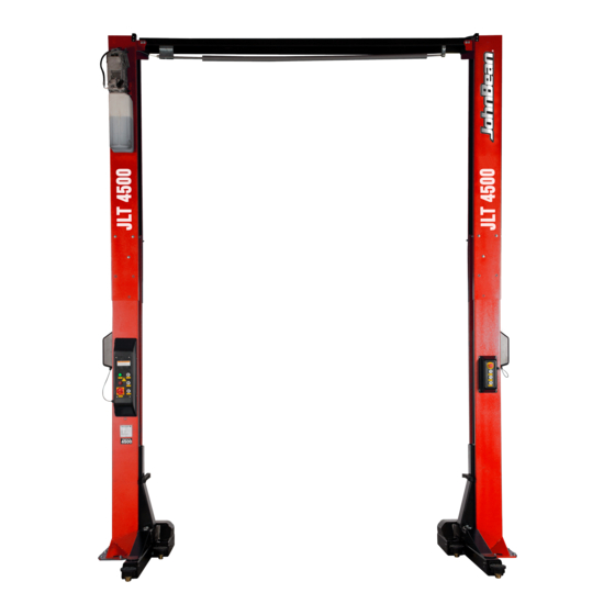
Tw o P o s t S u r f a c e M o u n t e d L i f t
4 5 0 0 k g c a p a c i t y
Voltage
400 V
230 V
S n a p - o n E q u i p m e n t E u r o p e
V i a P r o v. C a r p i , 3 3
4 2 0 1 5 C o r r e g g i o ( R E ) - I TA LY
FAX: +39 0522/733-479
Phone: +39 0522/733-480
www.snapon-equipment.eu
Web Site:
Original Instructions
Frequency
50 Hz
50 Hz
M O D E L S
J L T 4 5 0 0 S
J L T 4 5 0 0 T
Phases
3 PH
1 PH
1
Power
4.0 kW
4.0 kW
Advertisement
Table of Contents

Related Manuals for John Bean JLT4500S


Summary of Contents for John Bean JLT4500S
- Page 1 I NSTALLATION, O PERATION & M AINTENANCE M ANUAL Tw o P o s t S u r f a c e M o u n t e d L i f t M O D E L S J L T 4 5 0 0 S J L T 4 5 0 0 T 4 5 0 0 k g c a p a c i t y S n a p - o n E q u i p m e n t E u r o p e...
- Page 2 Snap-on Equipment Hungary Kft. H-9400 Sopron Somfalvi u. 13. Phone: +36-99-311-206 Fax: +36-99-312-232 Type of machine Passenger car and light truck 2 post lift Type JLT4500 Model(s) JLT4500S / JLT4500T Manufacturing year 2020 Snap-on Equipment Warranty & Liability REV 02 OCT 2020 JLT4500-IOM-F...
- Page 3 REV 02 OCT 2020 JLT4500-IOM-F...
-
Page 4: Table Of Contents
CONTENT 1 FOREWORD ....................................... 5 2 GENERAL SAFETY AND ACCIDENT-PREVENTION RULES ........................5 3 WORKPLACE ENVIRONMENT .................................. 6 4 RESIDUAL HAZARDS ....................................7 4.1 CRUSHING HAZARD..................................8 4.2 HAZARD OF THE VEHICLE TO FALL FROM THE LIFT ......................... 9 4.3 HAZARD OF OVERTURNING OF THE VEHICLE DUE TO INSTABILITY OF THE LOAD ............... 9 4.4 ELECTRIC HAZARD .................................. -
Page 5: Foreword
CAUTION This document is the exclusive property of Snap-on Incorporated which forbids its reproduction, either in part or wholly, without its explicit approval in writing. WARNING Only permit trained and authorized persons to perform maintenance/operate this equipment. Any person authorized to operate the lift shall be given copy of the manual; the owner of the lift shall make sure that any person authorized to use the lift has fully read and understood the present manual, therefore knowing how to use the lift in safe conditions. -
Page 6: Workplace Environment
DANGER In order to prevent risks to third parties and/or damages to things, before any operation takes place, the user shall make sure that there are not things or persons close to the lift before starting any working cycle. DANGER Before using the lift, make sure that required protective apparels are used (protective gloves, goggles…). -
Page 7: Residual Hazards
The use of loose-fitting working cloths (e.g. scarves, button-down shirts, etc.) can be hazardous. Always wear close-fitting garments. Any oil or grease on the floor shall be removed immediately to prevent any risk of slipping or falling. 4 RESIDUAL HAZARDS DANGER It is mandatory to the owner of the lift and/or the person in charge of it, to supply to the final user all the necessary information and aids to the safeguard of its physical health. -
Page 8: Crushing Hazard
DANGER The operator is considered an integral part of the control system with the lowering valve and lock release. During any lowering, the operator must verify no obstruction under the lift. If any fault occurs during lowering, the operator must immediately stop the lowering command upon indication of any problems. -
Page 9: Hazard Of The Vehicle To Fall From The Lift
DANGER Before standing under the raised vehicle, make sure that both the load lifting are held by the safety locks. 4.2 HAZARD OF THE VEHICLE TO FALL FROM THE LIFT This hazard is present during both the raising and the lowering phases. The user shall make sure that the vehicle is correctly positioned on the arms of the lift, as per the requirements given in §... -
Page 10: Electric Hazard
4.4 ELECTRIC HAZARD This hazard is present if the electric connections are not compliant to the applicable safety local norms. ATTENTION Before connecting the lift to the electric line, verify that the line itself is completely compliant to the enforced norm. Also make sure that the electric line can supply the needed power and that: •... -
Page 11: Emergency Stop
DANGER It is not allowed to perform any type of aid and/or maintenance operation to the lift while being operated. DANGER Before operating the lift, make sure that the vehicle to be lifted does not have any fluid leakages. If fluids are spilled on the floor immediately remove them. DANGER Do not wash the vehicle on the lift. -
Page 12: Jlt4500 Two Post Lift
4500 kg. Any other use of the lift is not allowed, was not considered during the designing phase and could compromise the safety of the lift. Table1 See Figure 1 JLT4500S JLT4500T Rise Height (Screw Pads Highest Position) 1969mm... - Page 13 Fig. 3, General Specifications & Service Bay Layout REV 02 OCT 2020 JLT4500-IOM-F...
-
Page 14: Layout
5.1.1 LAYOUT: The lift has been designed for an exclusive use on the indoor. It has not been considered and thus it is not allowed its use on the outdoor. DANGER Verify that all around the lift there is sufficient space in order to guarantee the correct use of the lift, according to the dimensions of the car to be repaired and in the respect of the local safety norms. -
Page 15: Installation
ATTENTION This lift has been evaluated only for an operating ambient temperature range of 10 – 40°C (41– 104°F). JohnBean does not assume any responsibility for the eventual damages to persons, objects and/or to the lift, caused by use which is inadequate and/or inconsistent with the prescription of this manual. -
Page 16: Storage
DANGER Always load, unload and handle the lift package paying the utmost attention to possible hazards, in particular make sure that there are no persons or things in the range of the lifting device. 5.2.2 STORAGE If the lift, before being unpacked, needs a temporary storage, keep it in a covered dry place. 5.2.3 UNPACKING Once positioned the load close to the point in which the lift shall be installed, remove the eventual packing. -
Page 17: Assembly
Recommended Anchor- HILTI HSA - Stud anchor, M16 x 182mm. The Anchor must have a minimum concrete effective embedment depth of 120mm. The effective embedment depth into the concrete floor of 120mm does not include tile or hard floor coverings. Concrete minimum thickness equals 200mm. -
Page 18: Installation
Torque wrench: If M16 (HILTI) mechanical anchors are used: 80 N·m minimum with 24 mm Hex socket; If M16 (FISCHER) mechanical anchors are used: 100 N·m minimum with 24 mm Hex socket; If M16 (HILTI) chemical anchors are used: 80 N·m minimum with 24 mm Hex socket; 3.6 m Step ladder Anti-Seize lubricant (for arm pins and foot pad screw threads and stop rings) A lifting device, such as a Crane or Fork lift, with a minimum admissible load of 1500 kg... - Page 19 Fig. 6, Route Idler Hose Route Idler Hose through Extension, see Fig.6. Based on your LAYOUT, connect below parts/ sub-assembly together, see Fig.7. Install the limit switch assembly onto cross member weldment (EAS2185T12A) with screws (M6x12, 1-02688A) & M6 nuts (1-15088A). Fig.7, Overhead Breakdown Assemble overhead sub-assembly (EAA0459T03A - 1) to idler column using only two of the mounting bolts and allow to pivot until it rests on the idler column (use protection between painted components), see Fig.8.
- Page 20 ONE BOLT ON THE SAME LOCATION OF EACH SIDE, HAND TIGHT ONLY. BOLT:M10x20,1-25788A; NUT M10,1-14788A WOODEN BLOCK Fig. 8, Install Overhead sub-assembly Assemble Power Column Extension (EAS2185T23A) to Power Column Assembly (EAA0459T01A), hand tighten hardware only at this time, see Fig.9. Fig.
- Page 21 Fig.10, Install the Mounting Bracket Fig.11, Power Unit Mounting Assemble Power Unit (EAH0072T07A) to Power Column Extension (EAM0138V97A), DO NOT fill with oil at this time, see Fig.11 Install Bulkhead fitting (EAH0072T09A) onto the power side extension column, then connect the Tee Branch Fitting (EAH0065V22A) with the bulkhead fitting from inside of the power side extension column, see Fig.12.
- Page 22 Connect one end of the Power Unit Hose (EAH0065V28A, L=490) to the installed Bulkhead fitting(EAH0072T09A), another end to the fitting (EAH0065V20A) on Power unit, see Fig. 13. EAH0065V28A Power Side Column Assembly Power Unit Power Side Column Extension EAH0072T09A EAH0065V20A 1-02088A, EAM0128V03A, M5X8, 4Pcs...
- Page 23 Fig. 15 Install anchor bolt Vacuum dust to clean out the hole for proper holding power, see step 2 of Fig. 15. Assemble the washer and nut onto anchor with nut just below impact section of anchor. Hammer in the anchor but leave 10mm space between the washer and base plate, see step 3 of Fig.
- Page 24 Hand tightens them Table 1, Fixing position for steel cables in one side carriage Model Configuration Cable PN 1st fixing plate 2nd fixing plate JLT4500S-Low Config.1:H3950 EAM0138T07A End of cable 2* End of cable 1 JLT4500S-High Config.3:H4300 EAM0138T07A...
- Page 25 Step 2, Get the free end of Cable 1 to cross the overhead sheave of the same side. Step 3, Get the free end of Cable 1 to cross the other overhead sheave on opposite column. Step 4, Route down to the opposite side carriage, fix the free end of Cable 1 according to Fig.19. Jam both end nuts together and Hand tightens them.
- Page 26 Power Idler Anti-derailment: Synchronizing cables side side Bolt, M10, 1-22588A, 4PCS Hose: EAH0072T00A EAM0138T07A Nut, M10, 1-14788A, 8PCS Hose Bracket: EAS2172V20A Hose Bracket: EAS2172V26A Bolt: 1-14988A, M6X16, 4PCS Bolt: 1-14988A, M6X16, 4PCS Connect free end Nut:1-15088A, M6, 4PCS Nut:1-15088A, M6, 4PCS of EAH0072T00A to EAH0065V22A Represents Hose Assembling Direction...
- Page 27 Fig. 22, Lubricate the footpad assembly 5.3.3.4 CONNECTION OF THE ELECTRIC BOX DANGER Do not connect the lift to the electric line before having verified that the line itself is completely compliant to the enforced norm. DANGER Do not connect the lift to the electric line before having verified that there is a properly working grounding circuit and there is a properly working protection circuit.
- Page 28 Note: W2 or W12, W3, W4, W5, W6, W8 have been installed in factory at C3-C6; H1 has been installed in factory at C1-C7; H2 has been installed in factory at C8-C14. H1 and H2 need to be pulled straightly when assembling the carriage in column, and should be fasten to the cable carrier at C1, C2, C13, C14 by wire ties at column bottom at both power side and idler side, see Fig.23.
- Page 29 Route electrical wiring harness for the Remote Control Box (RCB) which will be installed on Idler Side Column. W4/ W5: From C6 →C7 →GR1 → GR2 → GR3 → GR4 → C8 → C9→C10 →C11→Hole3 →the terminals in RCB, see Fig.25. Fig.
- Page 30 Secure electrical wiring harnesses with Hydraulic hoses using wire ties. Fasten electric wires at upper, middle, lower part of each space between two cable carriers (except space below C2 and C13), See Fig.27. upper middle lower Fig.27, Fasten electric wires Connect power supply by certified electrician, see Fig.28 Fig.
- Page 31 Fill Power Unit reservoir with approximately 12L of clean anti-foam antirust hydraulic oil based on section §5.6.3. DO NOT USE OILS WITH DETERGENTS. (Note: Do not overfill reservoir, the initial reservoir fill of approximately 8 liters will allow for bleeding the system. Add remaining amount of oil.) Fig.29, Routing Electrical wiring harness ATTENTION...
- Page 32 Fig.30, Recheck actuator setting Loose the M6 screw, flat washer should be added or removed if needed, the distance between column and CE stop should be adjusted to 26.5±1 to ensure an effective trigger, see Fig.31. Add or remove flat washers 26.5±1 mm Fig.31, Adjust CE stop plate in longitudinal direction Use proper hole on the CE stop plate and adjust the M6 screw along the slot direction to finally make the CE stop exceed plate 1mm by...
- Page 33 Visual check Fig.32, Adjust CE stop plate in transverse direction 5.3.3.6 FINAL ADJUSTMENTS – LOCK GEARS Factory has adjusted the lock gears engagement, normally, lift and swing the arm by hand, the lock gears should engage well, needn’t adjust in field. In case if it needs to be adjusted, please follow these steps. Loose the M12 screw, Move the lock gear in the direction of A or B to ensure the normal engagement of the lock gear, A is tightening and B is loosening, see Fig.33.
- Page 34 5.3.3.7 FINAL ADJUSTMENTS – HYDRAULICS ATTENTION There could be the presence of air in the hydraulic circuit, especially after the first installation or following some maintenance jobs. Pressurize system until cylinders engage carriages and lower to a comfortable working height (Around 300mm) to bleed cylinders. Start with Idler side first.
-
Page 35: Additional Information On The Hydraulic Circuit
5.3.4 ADDITIONAL INFORMATION ON THE HYDRAULIC CIRCUIT: Fig. 35, Hydraulic circuit The most important components of the hydraulic circuit (Fig. 35) are: Motor: 400V, AC/3PH/50Hz, 2850RPM, S3 15%, 4.0KW 230V, AC/1PH/50Hz, 2850RPM, S3 15%, 4.0KW Pump: 5.0mL/R Max Pressure Valve, Fixed relief pressure: 24 MPa Lowering Electro-Valve, 24VDC Check Valve Flow limiting device... -
Page 36: Owner/Employer's Responsabilities
DANGER Only use original replacement parts approved by JohnBean for the specific use with the JLT4500 type lift. 5.4 OWNER/EMPLOYER’S RESPONSABILITIES This lift has been designed and constructed according to CE norm in compliance with the 2006/42/EC Machine Directive (MD). The standard applies to lift manufactures, as well as to owners and employers. -
Page 37: Loading Of Vehicles
DANGER Before and during each working cycle check that the safety devices are working correctly. Stop using the lift and immediately call JohnBean technical department for assistance if they appear not to be working as required. 5.5.1 LOADING OF VEHICLES. Completely lower the lift and its support rubber plates. -
Page 38: Operating The Lift
5.5.2 OPERATING THE LIFT To start-up the lift, turn the main switch into the ON position. Then the lift can be controlled at power pack side or another side, see Fig. 36. LEFT PANEL, Main control box on power pack side column RIGHT PANEL, Remote control box on another side column Fig. -
Page 39: Lowering A Vehicle
5.5.3 LOWERING A VEHICLE DANGER The operator is considered an integral part of the control system with the manual lowering valve and lock release. During any lowering, the operator must verify no obstruction under the lift. If any fault occurs during lowering, the operator must immediately release the lowering button or press the Emergency Stop button upon indication of any problems. -
Page 40: Periodic Checks
DANGER Prior to any kind of maintenance and/or cleaning operation is performed, completely lower the carriages, unload the lift and make sure that there is no pressure in the hydraulic hoses and disconnect the power source from the lift. DANGER For the extraordinary maintenance of the JLT4500 type lift, address exclusively to the qualified JohnBean technical support. -
Page 41: Specific Checks
5.6.1.3 MONTHLY CHECKS: Torque concrete anchor bolts to required torque (check §5.3.3.2). Check overhead shutoff switch. While raising lift, operate overhead shutoff bar. Motor should stop when bar is raised, see Fig.16. Check DN limit switch (item 7 in §12.5 ), it should work well like the description in §5.5.3. ... -
Page 42: Hydraulic Oil Recommended
5.6.3 HYDRAULIC OIL RECOMMENDED. Here equivalents hydraulic oils recommend by JohnBean for the use with the JLT4500 type are listed: If any of the above-mentioned oils are available, use oil with a viscosity of 46 cst at 40°according to the ISO6743-4-ISO VG 46 norm. (Alternate Hydraulic oil according to ISO32 can be substituted) MANUFACTURER DESCRIPTION... -
Page 43: Dismantling Of The Lift And Scrapping
6 DISMANTLING OF THE LIFT AND SCRAPPING The system must be put out of service and disassembled only when its replacement has been decided. Regardless of any considerations on the convenience of the reuse of the lift either in part or as a whole, it must be stressed that the scattering of potentially toxic components is extremely hazardous. - Page 44 SYMPTOMS CHECK POINT ACTION The hydraulic lowering valve is leaking a) Refer to Technical assistance. The lift is lowering by itself There are leakages in the hydraulic circuit b) Check the hydraulic circuit for leakages a) Raise the lift until it is not possible to dis-engage The lift is not going down pushing The mechanical safety is engaged the lowering button...
-
Page 45: Spare Parts: General Instructions
9 SPARE PARTS: GENERAL INSTRUCTIONS ATTENTION When requesting spare parts, it is highly recommended to always specify not only the name of the person ordering them, the name of the Company and the telephone number, but also the following data: DESCRIPTION OF THE LIFT ON WHICH THE ITEM IS MOUNTED LIFT SERIAL NUMBER DESCRIPTION OF THE ITEM... -
Page 46: Parts Breakdown Of Final Assembly
9.1 PARTS BREAKDOWN OF FINAL ASSEMBLY Fig. 38, FINAL ASSEMBLY REV 02 OCT 2020 JLT4500-IOM-F... -
Page 47: T 6177.1-2000 M6 Nut
ITEM # PART # QTY/LIFT DESCRIPTION EAA0459T01A COLUMN ASSEMBLY 1-25788A GB 5789-86, M10×20 1-14788A HEX FLANGE NUT, GB/T 6177.1, M10 EAS2185V23A TOWER EXT.WELD, LS 1-15788A HEX FLANGE NUT,GB/T6177.1 ,M8 EAM0128V05A POWER UNIT BRACKET 1-05388A FLAT WASHER, GB/T 95-2002, 10 1-05488A SPRING WASHER GB/T 93-1987 ,10 1-18388A HEX BOLT GB/T 5781-2000, M10×20... -
Page 48: Parts Breakdown Of Overhead Assembly
9.2 PARTS BREAKDOWN OF OVERHEAD ASSEMBLY Fig. 39, OVERHEAD ASSEMBLY M6x12 CROSS RECESS HEAD SCREW GB/T ITEM # PART # QTY/LIFT DESCRIPTION 1-02688A 818-2000 EAS2185T12A CROSSMEMBER WELDMENT EAM0119V55A OVERHEAD BAR 1-04187A B TYPE PIN 10×55 GB 882-88 EAM0119V99A OVERHEAD BAR BRACKET 1-15088A HEX NUT GB/T 6177.1-2000 M6 EAM0119V90A... -
Page 49: Parts Breakdown Of Parts On Columns
9.3 PARTS BREAKDOWN OF PARTS ON COLUMNS Fig. 40, PARTS ON COLUMNS REV 02 OCT 2020 JLT4500-IOM-F... -
Page 50: Electromagner Bracket
ITEM # PART # QTY/LIFT DESCRIPTION 1-02088A CROSS RECESS HEAD SCREW DIN 7985 M5X8 CLASS 4.8 EAM0128V03A LOCK COVER EAE0070V02A SQ1880S-24B7.2 ELECTROMAGNET 1-01988A FLAT WASHER GB/T 95-2002 5 1-02588A CROSS RECESS HEAD SCREW GB/T818-2000 M5X10 1-02288A CROSS RECESS HEAD SCREW GB/T818-2000 M4X12 1-03188A FLAT WASHER GB/T95-2002 4 EAM0119V44A... -
Page 51: Parts Breakdown Of Hydraulic System
9.4 PARTS BREAKDOWN OF HYDRAULIC SYSTEM Fig. 41, HYDRAULIC SYSTEM ITEM # PART # QTY/LIFT DESCRIPTION EAH0065V18A END STRAIGHT COUPLING EAH0065V01A HYDRAULIC CYLINDER Until Sep2020 EAA0431V35A HYDRAULIC CYLINDER (modified flow restriction valve) From Oct2020 EAH0072T01A 4.5T 2-POST LS HYD HOSE ASSY EAH0065V20A FITTING ON PUMP EAH0065V28A... -
Page 52: Parts Breakdown Of Synchronizing System
9.5 PARTS BREAKDOWN OF SYNCHRONIZING SYSTEM Fig.42, SYNCHRONIZING SYSTEM REV 02 OCT 2020 JLT4500-IOM-F... - Page 53 ITEM # PART # QTY/LIFT DESCRIPTION 1-23777A EXTERNAL RETAINING RING, 30MM EAM0138T46A WASHER, PULLEY EAA0459T08A CABLE PULLEY ASSEMBLY EAS2185T13A LOWER PULLEY MOUNT WELD 1-04787A D6x50 CLEVIS PIN 1-17188A GB5789-86 M8×20 1-00488A M16 HEX NUT 1-22688A M16 THIN HEX NUT EAM0138T45A PULLEY SPACER EAM0138T34A PULLEY PIN...
-
Page 54: Parts Breakdown Of Carriage And Arms
9.6 PARTS BREAKDOWN OF CARRIAGE AND ARMS REV 02 OCT 2020 JLT4500-IOM-F... - Page 55 Fig. 43, CARRIAGES AND ARMS ITEM # PART # QTY/LIFT DESCRIPTION EAA0459V20A SLIDE BLOCK ASSEMBBLY EAS2185T01A CARRIAGE WELDMENT LS EAS2185V26A CARRIAGE WELDMENT RS EAM0119V71A TENSION SPRING EAM0138T31A INNER GEAR PIN 1-08389A GEAR LOCK SPRING GB/T2089-2009 YA 3×28×41 EAM0138V79A SMALL LOCK GEAR 1-00187A GB/T 894.1 25 RESTRAINING RING 1-24788A...
-
Page 56: Safety Pictograms On The Lift
ATTENTION Replace all worn or broken parts with genuine JohnBean parts. Contact your local Snap-on parts distributor for pricing and availability. Call JohnBean. at +39 0522/733-411 for the distributor in your area. 10 SAFETY PICTOGRAMS ON THE LIFT For your safety, and the safety of others, read and understand all of the safety notices and decals included here. WARNING The user of the lift must be a person able to fully understand and recognize all the pictograms installed on it. - Page 57 WARNING Do not attempt to raise a vehicle on the lift until the lift has been correctly installed and adjusted as described in this manual WARNING DO NOT operate the lift until its installation has been approved by a Technician authorized by JohnBean. DANGER Do not overload for any reason the lift.
-
Page 58: Initial Check Lists
11 INITIAL CHECK LISTS 11.1 CHECK PROCEDURE FOR LIFT Type of machine Passenger car and light truck 2 post lift Model(s): JLT4500S / JLT4500T Serial Number: Type: JLT4500 Manufacturing year: 2018 Manufacturer: Snap-on Equipment Hungary Kft. European address: Address: Snap-on Equipment Hungary Kft. -
Page 59: Annual Checks
11.2 ANNUAL CHECKS Check report This report is record of all audits for operation conducted and recorded by an inspector or expert. This lift was audited on DATE: ______________________________ and subjected to testing for operational readiness. Describe deficiencies found (if any) Extent of the Check: Pending Checks (if any): If there are (no*) concerns to limit this lift for operation. - Page 60 Check report This report is record of all audits for operation conducted and recorded by an inspector or expert. This lift was audited on DATE: ______________________________ and subjected to testing for operational readiness. Describe deficiencies found (if any) Extent of the Check: Pending Checks (if any): If there are (no*) concerns to limit this lift for operation.
- Page 61 Check report This report is record of all audits for operation conducted and recorded by an inspector or expert. This lift was audited on DATE: ______________________________ and subjected to testing for operational readiness. Describe deficiencies found (if any) Extent of the Check: Pending Checks (if any): If there are (no*) concerns to limit this lift for operation.
- Page 62 Check report This report is record of all audits for operation conducted and recorded by an inspector or expert. This lift was audited on DATE: ______________________________ and subjected to testing for operational readiness. Describe deficiencies found (if any) Extent of the Check: Pending Checks (if any): If there are (no*) concerns to limit this lift for operation.
- Page 63 Check report This report is record of all audits for operation conducted and recorded by an inspector or expert. This lift was audited on DATE: ______________________________ and subjected to testing for operational readiness. Describe deficiencies found (if any) Extent of the Check: Pending Checks (if any): If there are (no*) concerns to limit this lift for operation.
- Page 64 Check Report Summary Description Date and Name REV 02 OCT 2020 JLT4500-IOM-F...
-
Page 65: Electrical Diagram
12 ELECTRICAL DIAGRAM 12.1 WIRING DIAGRAM FOR THREE PHASES (SHEET 1/3) REV 02 OCT 2020 JLT4500-IOM-F... -
Page 66: Wiring Diagram For Single Phase (Sheet 2/3)
12.2 WIRING DIAGRAM FOR SINGLE PHASE (SHEET 2/3) REV 02 OCT 2020 JLT4500-IOM-F... -
Page 67: Wiring Diagram Of Control Boxes (Sheet 3/3)
12.3 WIRING DIAGRAM OF CONTROL BOXES (SHEET 3/3) REV 02 OCT 2020 JLT4500-IOM-F... -
Page 68: Wiring Diagram Of The Electrical System
12.4 WIRING DIAGRAM OF THE ELECTRICAL SYSTEM REV 02 OCT 2020 JLT4500-IOM-F... -
Page 69: Electrical Parts Of Main Control Box
12.5 ELECTRICAL PARTS OF MAIN CONTROL BOX Description TRANSFORMER Control Board LIMIT SWITCH FUSE BASE FUSE 2A for 400VAC FUSE 3A for 230VAC FUSE 10A CONTACTOR for 400VAC CONTACTOR for 230VAC The item EAE0082V26A should be adjusted as shown below before installed on the base plate. REV 02 OCT 2020 JLT4500-IOM-F... -
Page 70: Foundation Plan
13 FOUNDATION PLAN REV 02 OCT 2020 JLT4500-IOM-F... - Page 71 Product Change Notice REV. DESCRIPTION DATE Insert SECTION 9.4 PARTS BREAKDOWN OF HYDRAULIC SYSTEM on page 49 of the manual. Updated the fig.33 on DG07205 15OCT2019 page 31 of the manual. DG07293 Update the HYDRAULIC CYLINDER ASSEMBLY on page 49 of the manual. Updated the fig.35 on page 33 of the manual. 23MAR2020 Part number for control box cover &...
Need help?
Do you have a question about the JLT4500S and is the answer not in the manual?
Questions and answers