Table of Contents
Advertisement
Quick Links
READ and SAVE THIS
INSTRUCTION MANUAL
JUNE 2005
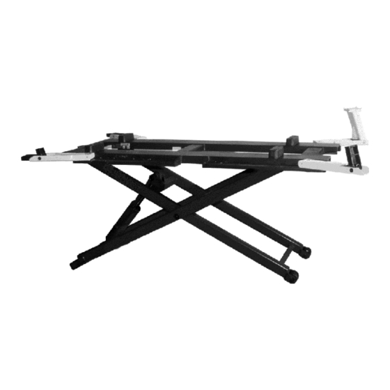
MID RISE
MID RISE
MODEL 410E6M / 410A6M
MODEL 410E6M / 410A6M
6,000 LB. CAPACITY
6,000 LB. CAPACITY
6-1339
INSTALLATION and
INSTALLATION and
OPERATION MANUAL
OPERATION MANUAL
309 EXCHANGE AVENUE, CONWAY, ARKANSAS, 72032
TEL: 501-450-1500 FAX: 501-450-1585
Advertisement
Table of Contents

Subscribe to Our Youtube Channel
Related Manuals for John Bean 410E6M


Summary of Contents for John Bean 410E6M
- Page 1 INSTALLATION and INSTALLATION and OPERATION MANUAL OPERATION MANUAL MID RISE MID RISE MODEL 410E6M / 410A6M MODEL 410E6M / 410A6M 6,000 LB. CAPACITY 6,000 LB. CAPACITY READ and SAVE THIS INSTRUCTION MANUAL 309 EXCHANGE AVENUE, CONWAY, ARKANSAS, 72032 TEL: 501-450-1500 FAX: 501-450-1585...
-
Page 2: Table Of Contents
TABLE OF CONTENTS PAGE GENERAL SPECIFICATION TOOLS REQUIRED SHIPPING CONTENTS INSTALLATION INSTRUCTIONS Unpacking Procedure Assembly Instructions Hydraulic System Installation Hydraulic System Bleeding Procedure POSITIONING INSTRUCTIONS OPERATING INSTRUCTION SAFETY INSTRUCTIONS MAINTENANCE INSTRUCTIONS Daily Maintenance Monthly Maintenance SAFETY AWARENESS PARTS MANUAL Mid-Rise Main Frame Assembly Mid-Rise Main Frame Assembly - Part List Hydraulic Cylinder Assembly Hydraulic Cylinder - Part List... -
Page 3: General Specification
1. GENERAL SPECIFICATIONS Maximum Capacity: 6,000 lbs. 2720 kg. Maximum Lift Height: 39.5” 1000mm Down Position Height: 5” 127mm Shipping Weight: 950 lbs. 430 kg. Lift Time 1. Electric Power Pack 30 seconds 2. Air Hydraulic Power Pack Electric 115 V 1 H.P. Motor, 1 PH Air Motor, 100 P.S.I Unique Automatic Mechanical Safety Hydraulic Velocity Fuse 2. -
Page 4: Installation Instructions
4. INSTALLATION INSTRUCTIONS When lift arrives on site, please read the owner’s manual and check for any freight damages. Also, check the contents to make sure no parts are missing before starting assembly. UNPACKING PROCEDURE Remove the metal strapping from the main structure package and slide the lift off the shipping skid. -
Page 5: Positioning Instructions
5. POSITIONING INSTRUCTIONS NOTE: Please review ALI safety card attached to tow cart and inspect lift for mechanical fitness before using. NOTE: Lifts must only be installed on “level” concrete floors, with a minimum thickness of five (5) inches. Concrete must have a minimum strength of 4,000 psi, and should be aged 30 days prior to installation and use of the lift in this area. -
Page 6: Operating Instruction
6. OPERATING INSTRUCTIONS 1. Raise the lift by pressing the “UP” button on the front face of the Power Pack Motor. 2. Continue raising the lift until the mechanical safety “CLICKS” into position. Always lower the lift in order to fully engage the mechanical safety lock. NOTE: All Mid-Rise lifts are equipped with dual safety locking devices, one (1) automatic mechanical safety bar, and second, a hydraulic velocity fuse to protect against hydraulic failure. - Page 7 Never attempt to overload the lift. The manufacturer’s rated capacity is shown on the serial number tag. Operating controls, DO NOT OVERRIDE the automatic safety devices incorporated into the Mid-Rise lift. Press the “UP” button on the front face of the power pack motor to go up.
-
Page 8: Daily Maintenance
8. RECOMMENDED MAINTENANCE MID-RISE DAILY MAINTENANCE Check general operation of lift. Check operation of automatic mechanical safety lock engaging and disengaging. Check condition of floor in roller area for cracks and debris. Check position of hydraulic hose, ensure that a vehicle positioned on the lift or the lift itself will not damage the hose. -
Page 9: Safety Awareness
SAFETY AWARENESS - AUTOMOTIVE LIFT INSTITUTE (ALI) -
Page 10: Mid-Rise Main Frame Assembly
MID-RISE MAIN FRAME ASSEMBLY... -
Page 11: Mid-Rise Main Frame Assembly - Part List
MID-RISE MAIN FRAME ASSEMBLY - PARTS LIST ITEM NO. QTY. DESCRIPTION PART NO. TOP RAMP ASSEMBLY 4-0200 RUBBER BLOCK 6-1074 ARM BOLT 1-1076 ARM ASSEMBLY L.H. 2-1809 LOW ADAPTER 3-0583 CENTER PIN 1-1099 FLAT WASHER 1/2" I.D. 6-0063 COTTER PIN 1/8" X 1" LG. 6-0267 HIGH STEP ADAPTER 3-0582... -
Page 12: Hydraulic Cylinder Assembly
HYDRAULIC CYLINDER ASSEMBLY... - Page 13 HYDRAULIC CYLINDER ASSEMBLY - PARTS LIST ITEM NO. QTY. DESCRIPTION PART NO. CYLINDER TUBE WELDMENT 3-0350 7/8"-9UNC HEX LOCKNUT 6-0631 WASHER, 7/8” I.D. 1-0809 PISTON SEAL KIT 0-0181 PISTON 2-0586 "O" RING 6-0656 PISTON ROD 2-0832 BEARING 6-0976 ROD CLEVIS 2-0833 90º...
-
Page 14: Power Pack Tow Cart
POWER PACK TOW CART... -
Page 15: Power Pack Tow Cart - Part List
POWER PACK TOW CART - PARTS LIST ITEM NO. QTY. DESCRIPTION PART NO. STAND (WITH WHEELS AND HUB CAP NUTS) 4-0207-01 ADAPTER-MACHINED W/ ORIFICES (.035”DIA) 1-1063 POWER PACK 115/230V 1PH 60HZ 1 HP 6-2249 GRIP HANDLE 6-0758 PLUG 6-1711 HEX BOLT 1/4"-20UNC 6-0028 LOCKWASHER 1/4"... -
Page 16: Power Pack
POWER PACK: #6-2249 (AB-1425) 115-230V/1PH/60Hz... - Page 17 POWER PACK PARTS LIST: #6-2249 (AB-1425) 115-230V/1PH/60Hz ITEM QTY. DESCRIPTION PART # BOLT 5/16”-24 x 2 ¾” TORX G8 6-2298 COUPLING SAE 9T-20/40 1.260” 6-0774 SEAL SHAFT 0.500” x 1.00” x 0.25” 6-2158 MOTOR AC PSC #613000 115/230 1 HP 1PH BLK 6-2299 WASHER 0.338”...
- Page 18 AIR POWER PACK...
- Page 19 AIR POWER PACK - PARTS LIST ITEM NO. QTY. DESCRIPTION PART NO. AIR HYDRAULIC PUMP 6-0919 “AC-10TC UTILIZING VA-4S VANE AIR MOTOR” HYDRAULIC HOSE - 12FT. 2-0602 BALL VALVE 6-0940 3/8” STEEL NIPPLE 6-0953 REDUCER 3/4” M PIPE/ 3/8” F PIPE 6-0285 EXHAUST MUFFLER 6-0958...
Need help?
Do you have a question about the 410E6M and is the answer not in the manual?
Questions and answers