Table of Contents
Advertisement
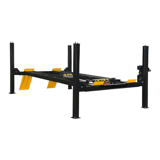
12K 4-Post Alignment Lift
INSTALLATION AND OPERATING MANUAL
READ THOROUGHLY BEFORE INSTALLING,
SERVICING OR MAINTAINING THE LIFT.
SAVE THIS MANUAL
INSTALLATION and OPERATION MANUAL
12K 4-Post Lift
EELR529A, EELR728A, EELR369A and EELR369A for Lift
EELS900A for Jacking Beam
309 EXCHANGE AVENUE, CONWAY, ARKANSAS, 72032
TEL: 501-450-1500 FAX: 501-450-1585
EAZ0080V51A
FEB 2019
REV.B
- 1 -
Advertisement
Table of Contents

Subscribe to Our Youtube Channel
Related Manuals for John Bean EELR529A


Summary of Contents for John Bean EELR529A
- Page 1 READ THOROUGHLY BEFORE INSTALLING, SERVICING OR MAINTAINING THE LIFT. SAVE THIS MANUAL INSTALLATION and OPERATION MANUAL 12K 4-Post Lift EELR529A, EELR728A, EELR369A and EELR369A for Lift EELS900A for Jacking Beam 309 EXCHANGE AVENUE, CONWAY, ARKANSAS, 72032 TEL: 501-450-1500 FAX: 501-450-1585 EAZ0080V51A FEB 2019 REV.B...
-
Page 2: Owner / User Obligations
1. OWNER / USER OBLIGATIONS 1. The Owner/User shall ensure that lift operators are qualified and that they are trained in the safe use and operation of the lift using the manufacturer’s operating instructions; ALI/SM 93-1, ALI Lifting it Right safety manual; ALI/ST-90 ALI Safety Tips card; ANSI/ALI ALOIM-2013, American National Standard for Automotive Lifts - Safety Requirements for Operation, Inspection and Maintenance, Appendix A (Operator Training Log);... -
Page 3: Important Safety Instructions
1.1 IMPORTANT SAFETY INSTRUCTIONS When using this lift, basic safety precautions should always be followed, including the following: 1. Only trained and authorized personnel should operate the lift or rolling jacks. Do not allow customers or bystanders to operate the lift or be in the shop area while lift is in use. 2. -
Page 4: Safety Warning Labels For 4-Post Surface Mounted Roll-On Lifts
1.2 SAFETY WARNING LABELS FOR 4-POST SURFACE MOUNTED ROLL-ON LIFTS SAVE THESE INSTRUCTIONS - 4 -... -
Page 5: Table Of Contents
2. TABLE OF CONTENTS OWNER / USER OBLIGATIONS ......................- 2 - 1.1 IMPORTANT SAFETY INSTRUCTIONS ................... - 3 - SAFETY WARNING LABELS FOR 4-POST SURFACE MOUNTED ROLL-ON LIFTS ....- 4 - TABLE OF CONTENTS ......................... - 5 - GENERAL SPECIFICATIONS ....................... -
Page 6: General Specifications
3. GENERAL SPECIFICATIONS Maximum Capacity 12,000 lb. 5450 kg Maximum Wheelbase – General Service 183” 4646 mm Maximum Wheelbase – 2-Wheel 168-13/16” 4288 mm Alignment Maximum Wheelbase – 4-Wheel 158-1/2” 4026 mm Alignment Minimum Wheelbase – 4-Wheel Alignment 88-1/2” 2248 mm Overall Length 251-1/2”... -
Page 7: Tools Required For Installation
4. TOOLS REQUIRED FOR INSTALLATION ROTARY HAMMER DRILL 3/4” CONCRETE DRILL BIT 1/2” CONCRETE DRILL BIT 4’ LEVEL HEIGHT GUAGE LASER LEVEL HAMMER (for anchor installation) PRY BAR (for shim installation) CHALK LINE (lift location) TAPE MEASURE ELECTRICAL TAPE STEP LADDER (adjusting cables and/or safety ladder in posts) SIDE CUTTERS (for cutting shipping straps) 4 WORK STANDS (set up) STANDARD SOCKETS AND WRENCHES... -
Page 8: Alignment Layout
6. ALIGNMENT LAYOUT Aligner mount holes Figure 2 - 8 -... -
Page 9: Installation Instructions
7. INSTALLATION INSTRUCTIONS PLEASE TAKE THE TIME TO READ THESE INSTRUCTIONS COMPLETELY. A QUICK CHECK OF THE CONTENTS OF THE ACCESSORY BOX WOULD ALSO DECREASE THE INSTALLATION TIME. Gather the tools and materials required for the installation. Select the location best suited for your lift. NOTE: In determining lift area check for the following: - Ease of driving a vehicle on and off the lift. -
Page 10: Chalk Line Layout
7.1 CHALK LINE LAYOUT Figure 3 NOTE: For alignment layout, please refer to Figure 2. None of the front anchors shall be closer than 8" to any edge of a concrete slab, expansion joint or crack in the garage floor. Review position of front towers, base plates and anchors, and relocate lines "A"- "F"... -
Page 11: Identification Of Main Lift Components
7.2 IDENTIFICATION OF MAIN LIFT COMPONENTS Identify and unpack major lift components (cables, columns, cross beams) and place them where they belong (front left, front right etc.) See Figure 4. Place components in their approximate locations. Do not unwind cables at this point. Leave cables coiled, close to their respective towers. -
Page 12: Cross-Beams And Runway Assemblies
HYDRAULIC CYLINDER MOUNT PLATE HYDRAULIC CYLINDER R.S. RUNWAY (DECK) L.S. RUNWAY (DECK) Identify and place coiled cables as follows, close to their respective towers (Table 1): All cables are pre-install in L.S. Runway, see Figure 5 CABLE S/N CABLE P/N LOCATION LENGTH CABLE 1... - Page 13 Route cable #1 through the idler runway, into the front cross beam access hole, and out the right end of the front beam. (Don’t forget to route it up over the cross-braces in the bottom of the runway.), Figure 9. ...
- Page 14 Cable 2 Cable 1 LEFT FRONT RIGHT FRONT Cable 3 RIGHT REAR JACK RAIL 1x4x12 4x4x30 Cable 4 LEFT REAR Figure 6 1/8 THICK WASHER 2 1/8’ SPACER 1/8 THICK WASHER REAR ONLY Figure 8 - Figure 7 - Front Single-Stack (typical Rear Single-Stack (idler runway) for idler and power runways) - 14 -...
- Page 15 Cable 1 Cable 3 Side to side distance Z to be identical Diagonals to be within 1/4“ Cable 2 Cable 4 Cable 2 Cable 1 Cable 3 Cable 4 Figure 9 - Cable Route Cable 3 Inside Deck and Cross Beam No need to fully pull out the pulley shaft, Figure 10 - Cable Pulley...
-
Page 16: Column Installation
7.4 COLUMN INSTALLATION Stand up a column assembly near each corner of the lift (column with power unit bracket goes at the front left corner, power front) and check the locking ladder bar orientation per Figure 11. Note that the center of the threaded rod is offset (away from the back of the column) from the center of the ladder. -
Page 17: Anchor Columns
7.5 ANCHOR COLUMNS Prior to installing anchors, assemble the nut and washer onto anchors. A minimum of six threads must be visible below the surface of the nut. Refer to the Figure 14 while reading through the following instructions. Figure 14 ... -
Page 18: Cable Installation
DO NOT use more than 1/2” (13mm) of shims. Anchor bolts supplied allow for a maximum of 1/2” (13mm) of shim. If more than 1/2” (13mm) of shims are required, DO NOT proceed with installation and contact Snap-on Equipment Technical Support for further details. NOTE: Refer to Figure 1 and Figure 3 to ensure that the column is still in the proper position. - Page 19 Be Certain All Fittings and Connections are Tight. It is the installers responsibility to ensure system is leak-free. Fill the Power Unit with three gallons of clean ISO 32 (10 weight) hydraulic oil. Do Not Use Oils with any detergent additives. ...
- Page 20 Figure 18 - 20 -...
- Page 21 10mm Jack Beam Poly tube(Black) Tee fitting 4mm Safety Release Poly tube(Blue) Straight fitting 4mm Safety Release Poly tube Straight fitting 4mm Safety Release Poly tube Figure 19 – Poly tube route Welded Rings All poly tube should route through these rings if available Figure 20 - 21 -...
-
Page 22: Install Front Turntables
7.8 INSTALL FRONT TURNTABLES Position the lift at a comfortable working height and lower onto a mechanical safety lock. Place each front turntable assembly on the front alignment pan of the runway. Moving lock handles of the turntables should be oriented to the outside of lift, See Figure 21 (a). -
Page 23: Decal Placement
7.9 DECAL PLACEMENT Clean the column surface before placing any decals. Install safety decals (NOTICE / CAUTION / WARNING) at the power unit as shown in Figure 22 below. An illustration of these safety decals can be found on page 4. Safety Decal Logo Decal Figure 23 -... - Page 24 The Owner/User shall ensure that lift operators are qualified and that they are trained in the safe use and operation of the lift using the manufacturer’s operating instructions; ALI/SM 93 -1, ALI Lifting it Right safety manual; ALI/ST-90 ALI Safety Tips card; ANSI/ALI ALOIM-2013, American National Standard for Automotive Lifts-Safety Requirements for Operation, Inspection and Maintenance;...
- Page 25 Raise the vehicle until locks are free. Disengage the locks by depressing the palm button and holding it. Lower the vehicle by depressing the lowering valve handle. Watch lift to ensure that the lift is lowering evenly. If not, raise lift and check all locks to ensure they are disengaged before trying to lower lift again.
-
Page 26: Parts List
10. PARTS LIST 10.1 LIFT ASSEMBLY Figure 24 - 26 -... - Page 27 ITEM# SOE PART# CL PART# DESCRIPTION EAH0068V20A B44011 1 PULL TYPE CYLINDER EAM0155V91A B40082 1 CYLINDER BOTTOM SHAFT 1-06787A B40126 1 D3.2X36 COTTER PIN GB/T91-2000 EAM0155V41A 1 DECK LS EAM0155V84A 1 DECK RS B40266 EAM0155V83A 2 FRONT WHEEL STOP 1-01588A 8 FLAT WASHER n 12 GB/T95-2002 1-01688A 8 SPRING WASHER D12 GB/T93-1987...
-
Page 28: Cables
10.2 CABLES Figure 25 ITEM# SOE PART# CL PART# DESCRIPTION EAA0485V10A STEEL ROPE FRONT RIGHT ASSY EAA0485V09A STEEL ROPE FRONT LEFT ASSY EAA0485V11A STEEL ROPE REAR RIGHT ASSY EAA0485V08A STEEL ROPE REAR LEFT ASSY 1-23288A 40147 HEX NUT 7/8-9 UNC ZINC 1-23388A B44015 M27 HEX JAM NUT... -
Page 29: Runway Pulleys
10.3 RUNWAY PULLEYS Figure 26 ITEM# SOE PART# CL PART# DESCRIPTION EAM0155V75A B40650 PULLEY ASSEMBLY WITH BUSHING EAM0155V74A B40053 PULLY WASHER EAM0155V71A B40055 DECK PULLEY SHAFT WELDMENT 1-26988A B31188 HEX BOLT M8X20 GB/T5781-2000 EAM0155V88A B40438-R STANDING BUSHING Replace all worn, damaged, or broken parts with parts approved by Snap-on Equipment. Contact 1-800-225-5786 - 29 -... -
Page 30: Cross Beam
10.4 CROSS BEAM Figure 27 ITEM# SOE PART# CL PART# DESCRIPTION JZQ7-04-01-00 EAS2205V04A CROSSBEAM WELDMENT B40127 EAM0155V29A SAFETY LOCK PIN B40126 1-02487A COTTER PIN B40134 EAS2205V07A SAFETY LOCK WELDMENT B40131 EAM0155V30A SAFETY DOG B40128 EAM0155V20A SAFETY WASHER B40132 EAM0155V32A SAFETY LOCK SPACER B40141 EAA0485V05A AIR CYLINDER ASSEMBLY... - Page 31 B31188 1-03515A M8 x 16mm LG HEX HEAD SCREW 40118 EAM0155V34A SLIDE GUIDE BLOCK JZQ7-04-02 EAM0130T59A PULLEY COVER CROSS RECESSED PAN HEAD TAPPING 1-23588A SCREWS GB845-85-ST6.3X12-F-H JSZ5.5-02-05 EAM0155V33A SAFETY PULLEY B40137 1-04987A RETAINING RING 9 GB/T 896-86 SOCKET HEAD CAP SCREW M8*20 1-17888A GB/T70.1-2008 Replace all worn, damaged, or broken parts with parts approved by Snap-on Equipment.
- Page 32 10.5 SLIP PLATE ASSEMBLY Figure 28 ITEM# SOE PART# CL PART# DESCRIPTION 40525 40525 BALL RETAINER ASSEMBLY 40211 40211 SLIP PLATE BALL 40221 40221 EXTENSION SPRING 1-27888A 40219 LOCK WASHER INTERNAL TEETH 40530 40530 REAR SLIP PLATE WELDMENT Replace all worn, damaged, or broken parts with parts approved by Snap-on Equipment. Contact 1-800-225-5786 - 32 -...
-
Page 33: Accessory
11. ACCESSORY 11.1 TURNTABLES ITEM# PART# DESCRIPTION QTY. EAK0289J06A TURNTABLE (OPTIONAL) EAK0277J28A PADDLE KIT, TT (OPTIONAL) 11.2 JACK BEAM AND ACCESSORY ITEM# PART# DESCRIPTION (OPTIONAL) QTY. EELS900A 6K JACK BEAM (OPTIONAL) 11.3 SHIM KIT ITEM# PART# DESCRIPTION QTY. 6-0739 LIFT SHIM KIT (included) 11.4 WORK STEP ITEM# PART#... -
Page 34: Appendix - A Installation, Operation & Maintenance Manual For Jack Beam
APPENDIX – A Installation, Operation & Maintenance Manual for Jack Beam EELS900A ODEL OLLING (Model EELR528A / EELR727A Series 4-Post) 6000 lbs. Capacity 309 EXCHANGE AVENUE, CONWAY, ARKANSAS, 72032 TEL: 501-450-1500 FAX: 501-450-1585 IMPORTANT: READ THIS MANUAL COMPLETELY BEFORE INSTALLING or OPERATING JACK - 34 -... - Page 35 Jack Beam Installation, Operation and Maintenance Manual CAUTION Before using this product, read and fully understand the operating instructions and all decals on the product. This is necessary to prevent injury to the operator and damage to the product. ...
- Page 36 Installation, Operation & Maintenance Manual for Jack Beam SPECFICATIONS: Capacity 6,000 lbs. 2725 kg 33” 838 mm Minimum Arm Reach Maximum Arm Reach 50-3/16” 1275 mm Minimum Lowered Height 3-1/8” 78.5 mm above Deck Surface Maximum Raised Height above 13-1/8” 332.5 mm Deck Surface Power Requirements @ 20...
- Page 37 Jack Beam Installation, Operation and Maintenance Manual Fig. 2 Operation Note: Before lifting a vehicle, operate the jack through a couple of cycles to become familiar with the controls. Roll jack forward before moving vehicle on lift rack. Be sure vehicle is centered on rack, apply parking brake and chock wheels.
- Page 38 Jack Beam Installation, Operation and Maintenance Manual Parts Breakdown - 38 -...
- Page 39 Jack Beam Installation, Operation and Maintenance Manual Item # CL Part # Qty/Jack Description RJ9-04-00 Footpad EAA0485V31A Air/Oil Pump VS10-31-08 M8 x 12 Flat Head Screw RJ6-19 Stop Bar RJ6-02CH RJ7.5-01 Sleeve RJ7.5-07F Outer Scissor Plate, Front RJ7.5-07R Outer Scissor Plate, Rear RJ6-06-04 Upper Pin Roller RJ6-13...
-
Page 40: Appendix - B Jack Beam Air Supply System
APPENDIX – B Jack Beam Air Supply System & O NSTALLATION PERATION ANUAL UPPLY YSTEM MPORTANT EAD THIS MANUAL COMPLETELY BEFORE INSTALLING OR OPERATING LIFT Read entire manual before assembling, installing, operating, or servicing this equipment. Proper maintenance and inspection is necessary for safe operation. - Page 41 AYOUT Figure 1 - 41 -...
- Page 42 Tee Fitting Installation (Pre-Installed) 3. Use provided zip ties to secure 1. Move lift to comfortable working height 10mm and rest in locks. air hose to the power runway as 2. Locate Ø21mm hole on the vertical wall of shown in Detail C. the power runway 1983mm from the front.
- Page 43 Coiled Hose Installation 1. Attach the coiled hose to the Tee in the runway and to the jacks. a. Remove two NPT 1/4’ PLUGs before connecting the short pigtail with the swivel end to the tee. Detail A. b. If there one Jack is on use, connect NPT 1/4’...
- Page 44 Coiled Hose to Jack Connection 1. When coiled hoses are attached to the jacks with the clamps provided, cut the provided Ø6mm OD plastic tubing into lengths shown in Figure 5 before installation and attach fittings by pushing onto end of tubing. 2.
- Page 45 Parts Breakdown ITEM# PART# Qty/Lift DESCRIPTION 1-00288A HEX NUT M8 GB/T 41-2000 EAM0156V22A CABLE HEAD EAA0485V07A ROPE ASSEMBLY EAH0075V27A ADAPTER NPT-MALE 1/4-Ø6 POLY EAH0075V25A POLY TUBE Ø6 1-26488A HEX BOLT M6X20 GB/T5783-2000 EAH0075V28A HOSE CLAMPØ8 1-26288A HEX NUT M6 GB/T6170-2000 Ø6 –...
Need help?
Do you have a question about the EELR529A and is the answer not in the manual?
Questions and answers