Table of Contents

Related Manuals for John Bean JBC319


Summary of Contents for John Bean JBC319
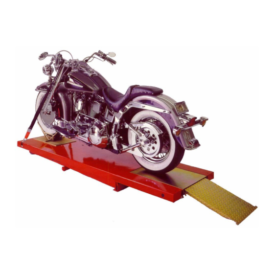
- Page 1 INSTALLATION and OPERATION MANUAL 1.5K MOTORCYCLE LIFT 1.5K MOTORCYCLE LIFT JBC319 JBC319 READ and SAVE THIS INSTRUCTION MANUAL 309 EXCHANGE AVENUE, CONWAY, ARKANSAS, 72032 AUG 07 REV.A 6-3060 TEL: 501-450-1500 FAX: 501-450-1585...
-
Page 2: Table Of Contents
TABLE OF CONTENTS ITEM PAGE 1. SAFETY AND OPERATING INSTRUCTIONS.............3 2. GENERAL SPECIFICATIONS ................5 3. CONTENTS.........................6 4. INSTALLATION REQUIREMENTS AND TOOLS ..........6 5. INSTALLATION INSTRUCTIONS.................7 5.1 UNPACKING PROCEDURE ................7 5.2 HYDRAULIC SYSTEM INSTALLATION............7 5.3 HYDRAULIC SYSTEM BLEEDING PROCEDURE........7 5.4 ANCHORING PROCEDURE................8 6. -
Page 3: Safety And Operating Instructions
SAFETY AND OPERATING INSTRUCTIONS 1. Read all safety and operating instructions before using the lift. 2. Inspect the lift daily. Do not operate the lift if it is damaged, malfunctioning, or if problems have been encountered. 3. Never attempt to overload the lift. The manufacturer’s rated capacity is shown on the serial number tag, located on the scissor assembly. - Page 4 17. Do not operate equipment with a damaged cord, or if the equipment has been dropped or damaged – until a qualified serviceman has examined it. 18. Do not let cord hang over table, bench or counter or come into contact with hot manifolds or moving fan blades.
-
Page 5: General Specifications
1. GENERAL SPECIFICATIONS Capacity: 1500lbs. 680kg Overall Width: 27” 686mm Overall Width (with Opt. Side Extension Kit): 51” 1295mm Overall Width (with Opt. Portable Kit): 48” 1219mm Overall Length: 89” 2261mm Overall Length (with Opt. Side Extension Kit): 112” 2845mm Overall Length (with Opt. -
Page 6: Contents
2. CONTENTS The complete lift is contained in two (2) packages: 1. The main structural components are packed on a shipping skid. 2. The remaining parts are packed in an accessory box. Main Structural Components include: 1pc. Deck-Scissor Assembly (including Pull-Out Pan and Approach Ramp) Accessory Box Contents: 1pc. -
Page 7: Installation Instructions
4. INSTALLATION INSTRUCTIONS 4.1 UNPACKING PROCEDURE Remove the metal strapping from the main structure package and slide the lift off the shipping skid. Open the accessory box and check the contents of the box. NOTE: The Power Pack is already installed on the Power Pack Stand 4.2 HYDRAULIC SYSTEM INSTALLATION 1. -
Page 8: Anchoring Procedure
4.4 ANCHORING PROCEDURE NOTE: The lift must always be anchored to a level and smooth floor. If the lift is to be operated in different locations, a portable kit, that includes a tow cart and outrigger, must be used. Note: When the tow cart is used, the lift must be in the fully down position and vehicles must be removed from the lift. -
Page 9: Operating Instructions
6. OPERATING INSTRUCTIONS 1. Raise the lift by pressing the “UP” button on the front face of the Power Pack Motor. 2. Continue raising the lift until the mechanical safety “CLICKS” into position. Always lower the lift to fully engage the mechanical safety lock. NOTE: All lifts are equipped with dual safety locking devices, an automatic mechanical safety bar, and a flow control to protect against hydraulic failure. - Page 10 4. Check and lubricate the automatic safety release device. 5. Inspect the 115V plug end and cable. 6. Inspect the main structure of the power pack stand. 7. Inspect the lift area for debris and concrete condition. 10 of 18...
-
Page 11: Main Frame Assembly
MAIN FRAME ASSEMBLY 11 of 18... -
Page 12: Main Frame Assembly - Parts List
7.3 MAIN FRAME ASSEMBLY - PARTS LIST ITEM NO. QTY. DESCRIPTION PART NO. DECK WELDMENT 4-0615 PULL-OUT PAN ASSEMBLY 3-0668 PULL-OUT PAN RAMP WELDMENT 3-0672 INNER SCISSOR WELDMENT 4-0618 FLAT WASHER, 3/4" SAE 6-0738 BRONZE BUSHING 6-1687 ROLLER CASTING 1-1664 ROLLER PIN 1-1665 SPRING PIN, 3/16"... -
Page 13: Hydraulic Cylinder Assembly
7.4 HYDRAULIC CYLINDER ASSEMBLY 13 of 18... -
Page 14: Hydraulic Cylinder Assembly - Parts List
7.5 HYDRAULIC CYLINDER ASSEMBLY - PARTS LIST ITEM NO. QTY. DESCRIPTION PART NO. CYLINDER TUBE WELDMENT 2-1323 PISTON ROD WELDMENT 2-1324 GLAND 1-1669 WEAR RING 1 3/8”ID x 1 1/2”OD x 3/8”LG 6-1679 PISTON (2” BORE) 2-0511 ALLEN HD SET SCREW 1/4”-20UNC x 3/8”LG 6-0580 SEAL AND WEAR RING 6-0579... -
Page 15: Power Pack Stand
7.8 POWER PACK STAND 15 of 18... -
Page 16: Power Pack Stand - Parts List
7.9 POWER PACK STAND - PARTS LIST ITEM NO. QTY. DESCRIPTION PART NO. STAND WELDING ( 4-0207-01 WITH WHEELS & HUB) 4” DIA PLASTIC WHEEL 6-0753 HUBCAP NUT 6-1833 6-1093 ELBOW 90° ¼” JIC TO 9/16” SAE POWER PACK 115V 3/4 HP* 6-2249 GRIP HANDLE 6-0758... -
Page 17: Power Pack: #6-2249 (Ab-1425) 115-230V/1Ph/60Hz
7.10 POWER PACK: #6-2249 (AB-1425) 115-230V/1PH/60Hz 17 of 18... -
Page 18: Power Pack Parts List: #6-2249 (Ab-1425) 115-230V/1Ph/60Hz
9.10 POWER PACK PARTS LIST: #6-2249 (AB-1425) 115-230V/1PH/60Hz ITEM QTY. DESCRIPTION PART # BOLT 5/16”-24 x 2 ¾” TORX G8 6-2298 COUPLING SAE 9T-20/40 1.260” 6-0774 SEAL SHAFT 0.500” x 1.00” x 0.25” 6-2158 MOTOR AC PSC #613000 115/230 1 HP 1PH BLK 6-2299 WASHER 0.338”...
Need help?
Do you have a question about the JBC319 and is the answer not in the manual?
Questions and answers