Table of Contents
Advertisement
I
NSTALLATION
Surface Mounted Lift
M
309 Exchange Avenue, Conway, Arkansas, 72032
IMPORTANT:
, O
& M
PERATION
Two Post
EELR537A
ODEL
12,000
. C
LBS
3000
.
LBS
PER
Snap-on Equipment
Tel: 501-450-1500
Fax: 501-450-1585
READ THIS MANUAL COMPLETELY BEFORE
INSTALLING or OPERATING LIFT
AINTENANCE
APACITY
A
RM
M
ANUAL
Rev. 09/16/2021
Advertisement
Table of Contents

Related Manuals for John Bean EELR537A


Summary of Contents for John Bean EELR537A
- Page 1 & M NSTALLATION PERATION AINTENANCE ANUAL Two Post Surface Mounted Lift EELR537A ODEL 12,000 APACITY 3000 Snap-on Equipment 309 Exchange Avenue, Conway, Arkansas, 72032 Tel: 501-450-1500 Fax: 501-450-1585 IMPORTANT: READ THIS MANUAL COMPLETELY BEFORE INSTALLING or OPERATING LIFT Rev. 09/16/2021...
-
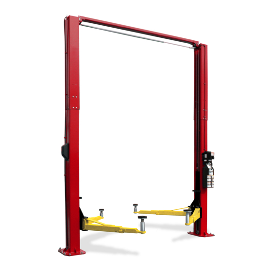
Page 2: General Specifications
Model EELR537A Installation, Operation and Maintenance ENERAL PECIFICATIONS See Figure 1 EELR537A EELR537A w/ 2 Ft. Ext. Kit Overall Height 13’-10"/14’-7” (4216 mm/4445 mm) Ceiling Height Required 167"/176” 191"/200” (4242mm/4470mm) (4852mm/ 4890mm) 15’-3 ½"/16’-½” Floor to Overhead Switch 13’-3 ½"/14’-½”... - Page 3 Model EELR537A Installation, Operation and Maintenance Safety decals similar to those shown here ERTICAL LEARANCE are found on a properly installed lift. Be sure Check the height of the area where the lift is to that all safety decals have been correctly be installed.
-
Page 4: Installation
Model EELR537A Installation, Operation and Maintenance ECEIVING NSTALLATION The shipment should be thoroughly inspected as AFETY EQUIREMENTS FOR NSTALLATION AND soon as it is received. The signed bill of lading is ERVICE acknowledgement by the carrier of receipt in Refer to ANSI/ALI ALIS (current edition) - Page 5 Model EELR537A Installation, Operation and Maintenance NCHORING 4) The anchor bolts must be installed at least 8” from any crack, edge, or expansion joint. 5) Use a concrete hammer drill with a 3/4 inch carbide bit. Tip diameter should conform to ANSI Standard B94.12-1977 (.775 to .787).
- Page 6 Model EELR537A Installation, Operation and Maintenance Fig. 5 – Synchronizing Cables & H OWER YDRAULIC INES 19) Mount Power Unit to power column as shown in Fig. 6 using (4) M8 hex bolts and nuts. 20) Attach Hydraulic elbow fitting threading the Fig.
-
Page 7: Arm Installation
Model EELR537A Installation, Operation and Maintenance Fig. 7 – Power Side Routing ELEASE 27) Install Lock Release Rod, Clevis, and Knob to the Power Column Lock using one M10 Nut. 28) Attach Mechanical Lock Release Cable Assembly to each lock pawl. See Fig. 8. - Page 8 Model EELR537A Installation, Operation and Maintenance 39) Connect Overhead Limit Switch Cord to squeal sound for these 10 seconds.) Check Contactor as shown. hydraulic system for leaks. 40) Connect Contactor to Power unit as shown. 47) Energize power unit again for 10 seconds.
- Page 9 Model EELR537A Installation, Operation and Maintenance Wiring Diagram FOR SINGLE PHASE FIELD CONECTIONS (Normally Open) FIELD CONECTIONS FOR THREE PHASE FACTORY WIRED FOR 208−240V RECONNECTIONS FOR 440−480V Fig 11 – Electrical Wiring Diagram Page 9 Rev. 09/16/2021 EELR537A-IOM.
-
Page 10: Operation Procedure
Model EELR537A Installation, Operation and Maintenance 1, ALI Lifting it Right safety manual; ALI/ST-90 ALI PERATION ROCEDURE Safety Tips card; ANSI/ALI ALOIM, American National Standard for Automotive Lifts-Safety AFETY OTICES AND ECALS Requirements for Operation, Inspection and This product is furnished with graphic safety Maintenance;... - Page 11 Model EELR537A Installation, Operation and Maintenance IFTING A EHICLE OSS OF POWER 1) Ensure that the lifting arms are parked, out to If for any reason the lift will not rise off the locks or full drive thru position. the locks will not retract, consult factory authorized personnel.
-
Page 12: Maintenance
Model EELR537A Installation, Operation and Maintenance AINTENANCE Monthly To avoid personal injury, permit only qualified Torque concrete anchor bolts to 80 ft-lbs. personnel to perform maintenance on this equipment. Maintenance personnel should follow Check overhead shutoff switch. While raising lift, lockout/tagout instructions per ANSI Z244.1. -
Page 13: Parts Breakdown
Model EELR537A Installation, Operation and Maintenance ARTS REAKDOWN ITEM # PART # QTY/LIFT DESCRIPTION L6-02-02-01 COLUMN EXTENSION (Std. Height) L6-02-02-01H COLUMN EXTENSION (2Ft. Ext. Height) L6-03-01-00K OVERHEAD WELD, BLACK JSJ6-03-02 OVERHEAD SHUT OFF BAR JSJ5-03-03 OVERHEAD SHUT OFF BAR CUSHION... - Page 14 Model EELR537A Installation, Operation and Maintenance ITEM # PART # QTY/LIFT DESCRIPTION L6-02-01-00 POWER COLUMN WELD L6-02-01-00F IDLER COLUMN WELD 1-16288a SHOULDER BOLT 1-16388A M12 LOCK NUT JSJ5-02-07CH LOCK SPRING, 3/8” O.D. JSJ5-02-08CH LOCK SPRING, ½” O.D. B1140 LOCK PAWL...
- Page 15 Model EELR537A Installation, Operation and Maintenance ITEM # PART # QTY/LIFT DESCRIPTION JSJ6-07-00 HYDRAULIC CYLINDER JSJ6-21 5/8-18 UN 90 DEGREE ELBOW JSJ6-20 5/8-18 UN HOSE EXTENSION (18 ½” LONG) (Std. Height) JSJ6-21H 5/8-18 UN HOSE EXTENSION (66 ½” LONG) (2Ft. Ext. Height) JSJ6-18 5/8-18 UN HOSE (411”...
- Page 16 Model EELR537A Installation, Operation and Maintenance ITEM # PART # QTY/LIFT DESCRIPTION JSJ6-04-00K SYNCHRONIZER CABLE (Std. Height) JSJ6-04-00HK SYNCHRONIZER CABLE (2Ft. Ext. Height) GJY12-3 HAIRPIN COTTER PIN JSJ6-03-08 CABLE SHEAVE X10-055 26mm WASHER JSJ6-03-03 CABLE SHEAVE PIN JSJ6-03-05 SHEAVE SPACER...
- Page 17 Model EELR537A Installation, Operation and Maintenance ITEM # PART # QTY/LIFT DESCRIPTION JSJ6-08-00K CARRIAGE JSJ5-08-15 SLIDE BLOCKS JSJ6-11 ARM PIN JSJ4-05-ch DOOR GUARD X10-087 M8 WASHER X10-088 M8 x 30mm Lg. SOCKET HEAD BOLT X10-077 M10 x 25mm Lg. SOCKET HEAD BOLT...
- Page 18 Model EELR537A Installation, Operation and Maintenance NOTES Page 18 Rev. 09/16/2021 EELR537A-IOM.
- Page 19 Model EELR537A Installation, Operation and Maintenance REVISIONS 03/06/20- UPDATED PART NUMBERS IN PARTS BREAKDOWN FOR POWER COLUMN, IDLER COLUMN, COLUMN EXTENSIONS, & OVERHEAD. 09/16/2021- UPDATED FOOTPAD IN PBD, REORDERED SPEC PAGE, OUTDOOR INSTALLATION IS PROHIBITED, ADDED ANCHOR BOLT TO PBD, AND CHANGED JSJ6-03-...
Need help?
Do you have a question about the EELR537A and is the answer not in the manual?
Questions and answers