Advertisement
Quick Links
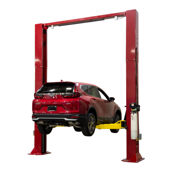
Installation, Operation & Maintenance Manual
Two Post Surface Mounted Lift
M
EELR538A & EELR539A
ODEL
M
EELR540A & EELR541A
ODEL
309 Exchange Avenue, Conway, Arkansas, 72032
IMPORTANT:
15,000
C
- 3750
LB
APACITY
18,000
C
– 4500
LB
APACITY
Snap-on Equipment
Tel: 501-450-1500
Fax: 501-450-1585
READ THIS MANUAL COMPLETELY BEFORE
INSTALLING or OPERATING LIFT
P
A
LB
ER
RM
LB PER ARM
Rev. 08/27/2021
Advertisement

Related Manuals for John Bean EELR538A


Summary of Contents for John Bean EELR538A
- Page 1 Installation, Operation & Maintenance Manual Two Post Surface Mounted Lift EELR538A & EELR539A ODEL 15,000 - 3750 APACITY EELR540A & EELR541A ODEL 18,000 – 4500 APACITY LB PER ARM Snap-on Equipment 309 Exchange Avenue, Conway, Arkansas, 72032 Tel: 501-450-1500 Fax: 501-450-1585...
- Page 2 Models EELR538A and EELR539A Models EELR540A and EELR541A Installation, Operation and Maintenance ENERAL PECIFICATIONS See Figure 1 EELR538A EELR539A EELR540A EELR541A 174” [14’-6”] 198” [16’-6”] 174” [14’-6”] 198” [16’-6”] Column Height Ceiling Height Required 176” 200” 176” 200” 167” [13’-11”] 191”...
- Page 3 Models EELR538A and EELR539A Models EELR540A and EELR541A Installation, Operation and Maintenance EAD ENTIRE MANUAL BEFORE ASSEMBLING ERTICAL LEARANCE INSTALLING OPERATING OR SERVICING THIS Check the height of the area where the lift is to be EQUIPMENT installed. Clearance should be calculated based on ROPER MAINTENANCE AND INSPECTION IS NECESSARY the full raised height of the lift.
- Page 4 Models EELR538A and EELR539A Models EELR540A and EELR541A Installation, Operation and Maintenance ECEIVING NSTALLATION The shipment should be thoroughly inspected as AFETY EQUIREMENTS FOR NSTALLATION AND soon as it is received. The signed bill of lading is ERVICE acknowledgement by the carrier of receipt in good Refer to ANSI/ALI ALIS (current edition) condition of shipment covered by our invoice.
- Page 5 Models EELR538A and EELR539A Models EELR540A and EELR541A Installation, Operation and Maintenance 4) Install the locking pawl, actuator, and spring VERHEAD (Fig. 2). Adjust air cylinder clevis to retract lock 12) Before raising overhead into position install 4 against inside of back of column when air each (2 per column) hex flange bolts and nuts in cylinder is fully extended.
- Page 6 Models EELR538A and EELR539A Models EELR540A and EELR541A Installation, Operation and Maintenance 15) Install the Idler Bracket to the Overhead Beam using the rear set of holes on the Idler Side of the lift. Fig. 6. Note the orientation of the Idler Bracket.
- Page 7 Models EELR538A and EELR539A Models EELR540A and EELR541A Installation, Operation and Maintenance 18) Route the synchronizer cables as shown in Fig. 9. Routing the cable from the inner hole location on the top of the carriage down to the column pulley and up to the overhead pulley.
- Page 8 Models EELR538A and EELR539A Models EELR540A and EELR541A Installation, Operation and Maintenance Fig. 13-Hose and Line Clamps 23) Hoses should connect to cylinders with a 90 degree elbow rotated 25 degrees upward and Fig. 14-Lock Release be routed thru hose guide (Fig. 13B).
- Page 9 Models EELR538A and EELR539A Models EELR540A and EELR541A Installation, Operation and Maintenance DAPTER NSTALLATION INAL DJUSTMENTS YDRAULICS 31) Locate the two pre-drilled holes on the back of 36) Lower the lift to the floor and raise the lift each column 19” up from the top of the base approximately one foot.
- Page 10 Models EELR538A and EELR539A Models EELR540A and EELR541A Installation, Operation and Maintenance Wiring Diagram FOR SINGLE PHASE FIELD CONECTIONS (Normally Open) FIELD CONECTIONS FOR THREE PHASE FACTORY WIRED FOR 208−240V RECONNECTIONS FOR 440−480V Fig 17 – Electrical Wiring Diagram Page 10 Rev.
- Page 11 Models EELR538A and EELR539A Models EELR540A and EELR541A Installation, Operation and Maintenance Maintenance; and in the case of frame engaging lift, PERATION ROCEDURE ALI/LP-GUIDE, Vehicle Lifting Points/Quick Reference Guide for Frame Engaging Lifts; in a AFETY OTICES AND ECALS conspicuous location in the lift area convenient to This product is furnished with graphic safety the operator.
- Page 12 Models EELR538A and EELR539A Models EELR540A and EELR541A Installation, Operation and Maintenance IFTING A EHICLE OSS OF POWER 1) Insure that the lifting arms are parked, out to full If for any reason the lift will not raise off the locks or drive thru position.
- Page 13 Models EELR538A and EELR539A Models EELR540A and EELR541A Installation, Operation and Maintenance ARTS REAKDOWN Fig A. Column Extension & Overhead ITEM # PART # QTY/LIFT DESCRIPTION 12025 POWER COLUMN WELD 12026 IDLER COLUMN WELD 12102 COLUMN EXTENSION (14’-6” O.A. Ht.) 12022 COLUMN EXTENSION (16’-6”...
- Page 14 Models EELR538A and EELR539A Models EELR540A and EELR541A Installation, Operation and Maintenance PARTS BREAKDOWN (continued) Fig B. Lock-Power/Idler Page 14 Rev. 08/27/2021 15-18000-IOM-W.doc...
- Page 15 Models EELR538A and EELR539A Models EELR540A and EELR541A Installation, Operation and Maintenance Table B. Lock-Power/Idler ITEM # PART # QTY/LIFT DESCRIPTION 37019 ELBOW 1/8” NPTM x 1/8” PUSH-LOCK 37022 #8-32 x 1 1/4” Lg. PAN HEAD SCREW 37015 BUTTON VALVE BRACKET...
- Page 16 Models EELR538A and EELR539A Models EELR540A and EELR541A Installation, Operation and Maintenance PARTS BREAKDOWN (continued) Fig C. Hydraulics ITEM # PART # QTY/LIFT DESCRIPTION 15075 HYD. CYLINDER (69” STROKE) 12111 CYLINDER SPACER 12258 POWER HOSE ASSEMBLY 12539-024 EXTENSION HYD. LINE (16’-6” O.A. HT. ONLY)
- Page 17 Models EELR538A and EELR539A Models EELR540A and EELR541A Installation, Operation and Maintenance PARTS BREAKDOWN (continued) Fig D. Synchronizer ITEM # PART # QTY/LIFT DESCRIPTION A1153 3/8-16 x 3/4" Lg. LOCK HEX FLG. HD.CAP SCREW A2158 Ø1/4” x 1 3/4” Lg. CLEVIS PIN...
- Page 18 Models EELR538A and EELR539A Models EELR540A and EELR541A Installation, Operation and Maintenance PARTS BREAKDOWN (continued) Fig E. Carriage & Arms ITEM # PART # DESCRIPTION ITEM # 12021 SLIDE BLOCK B12007-18 CARRIAGE WELD B12046 ARM PIN 12060 LINK WELD 31112 1/2”-13NC x 1 1/2”...
- Page 19 Models EELR538A and EELR539A Models EELR540A and EELR541A Installation, Operation and Maintenance REVISIONS 11/06/2019- THE ADAPTER RACK INSTALLATION INSTRUCTIONS WERE UPDATED TO CALL OUT 5/16-18 HARDWARE. 12/03/2019- SPEC PAGE HAS BEEN UPDATED WITH PAD HEIGHTS, MALE ARM HEIGHT, AND ARM SWING.
Need help?
Do you have a question about the EELR538A and is the answer not in the manual?
Questions and answers