Viessmann Vitocell 100-E Installation And Service Instructions Manual
Hide thumbs
Also See for Vitocell 100-E:

Related Manuals for Viessmann Vitocell 100-E


Summary of Contents for Viessmann Vitocell 100-E
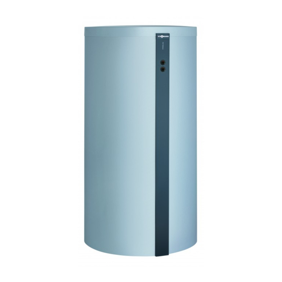
- Page 1 VIESMANN Installation and service instructions for contractors Vitocell 100-E Type SVPA Heating water buffer cylinder For applicability, see the last page VITOCELL 100-E Please keep safe. 5674 591 GB 1/2015...
- Page 2 Note For replacements, use only original spare parts Details identified by the word "Note" contain additional supplied or approved by Viessmann. information. Target group These instructions are exclusively intended for author- ised contractors.
-
Page 3: Table Of Contents
Index Index Information Symbols ....................Intended use ..................Product information ................Preparing for installation Connections ................... Installation sequence Siting the Vitocell ................... Fitting the lower thermal insulation mat; levelling the Vitocell ....Fitting the thermometer sensor (if available) ......... Fitting the Vitotrans ................Fitting the thermal insulation jacket ............ -
Page 4: Information Symbols
Information Symbols Symbol Meaning Reference to other document containing further information Step in a diagram: The numbers correspond to the order in which the steps are carried out. Warning of material losses and environ- mental pollution Live electrical area Pay particular attention. Component must audibly click into place. -
Page 5: Product Information
Information Product information Vitocell 100-E, type SVPA (600, 750 and 950 l capacity). ■ Steel heating water buffer cylinders for storing heat- ing water in combination with heat pumps, solar ther- mal systems, solid fuel boilers and heat recovery. With the option to fit a Vitotrans 353 ■... -
Page 6: Preparing For Installation Connections
Preparing for installation Connections Fig. Front Fig. Back Thermometer sensor retainer Heating water flow 1 (HF1) to the heating circuits / Thermometer (TH) up to 4 pce (accessory) air vent valve (EL) Heating water flow G 1 Heating water flow 2 (HF2) from the heat source Return stratification G 1 Sensor well (SPR1) for cylinder temperature sensor Heating water return G 1... -
Page 7: Installation Sequence Siting The Vitocell
Installation sequence Siting the Vitocell Please note Please note Exposure to frost can cause material damage. The thermal insulation must not come into con- Install the buffer cylinder in a room that is free tact with naked flames. from the risk of frost and draughts. Otherwise Exercise caution when welding and soldering. -
Page 8: Fitting The Thermometer Sensor (If Available)
Installation sequence Fitting the lower thermal insulation mat;… (cont.) 3. Screw the adjustable feet into the supports as far as they will go, then adjust them to level the cylin- der. Note Never extend the adjustable feet beyond a total length of 35 mm. -
Page 9: Fitting The Vitotrans
Installation sequence Fitting the thermometer sensor (if available) (cont.) 3. Route the thermometer sensor capillaries to the 5. Secure the sensor to the outside of the sensor back. retainer contact spring so that it is flush with the front of the spring. Note Repeat the following steps for each of the thermom- Note... - Page 10 Installation sequence Fitting the Vitotrans (cont.) Fig.4 1. Fit the bolts to the cylinder. 3. Screw the nuts onto the bolts until hand-tight. 2. Fit the module.
- Page 11 Installation sequence Fitting the Vitotrans (cont.) DE F Fig.5 1. Connect heating water flow connection pipe 3. Connect return stratification connection pipe connection on the Vitotrans. connection on the Vitotrans. 2. Connect heating water return connection pipe 4. Connect the pipes to the cylinder connections. connection on the Vitotrans.
-
Page 12: Fitting The Thermal Insulation Jacket
Installation sequence Fitting the thermal insulation jacket Note Ensure that no fleece remnants enter the heating water buffer cylinder through the cylinder connections. Fig.6 Note 2. Fit 4 clip fasteners above and 2 clip fasteners 2 people are required for the following work. behind the Vitotrans so that they are evenly spaced. -
Page 13: Fitting The Cover Strips
Installation sequence Fitting the cover strips Fig.7 1. Tighten the nuts on the bolts. 3. Insert the rear sections of the Vitotrans thermal insulation. Observe the groove in the thermal insu- 2. Trim and fit the cover strip. lation. - Page 14 Installation sequence Fitting the cover strips (cont.) Fig.8 Type plate (self-adhesive)
-
Page 15: Fitting The Cover
3. Fit the rear strip to the thermal insulation. tion. 4. Affix the type plate. 2. Push the cylinder thermal insulation towards the front by patting it. This reduces the gap between the Vitotrans and the cylinder. Fitting the cover Fig.9 Viessmann logo... -
Page 16: Fitting The Cylinder Temperature Sensor
Installation sequence Fitting the cylinder temperature sensor Note The cylinder temperature sensor is supplied in the con- trol unit pack. Fig.10 Sensor well positions Note ■ Never wrap insulating tape around the sensor. ■ Position the sensor on the outside of the sensor retainer contact spring (not in the groove) so that it is flush with the front of the spring. - Page 17 Installation sequence Connections on the heating water side (cont.) 2. Install the flow line with a rise and fit an air vent 3. Check all connections for leaks after filling the cylin- valve at the highest point. der. Cylinder bank connected in series Fig.11 Heating water return 3 (HR3) from the heating cir- Heating water flow 2 (HF2) from the heat source...
-
Page 18: Connecting The Equipotential Bonding
Installation sequence Connecting the equipotential bonding Connect the equipotential bonding in accordance with the requirements stipulated by your local power supply utility and VDE regulations. : Connect the equipotential bonding in accordance with the technical requirements stipulated by your local power supply utility and SEV regulations. -
Page 19: Parts Lists Overview Of Assemblies
Parts lists Overview of assemblies The following details are required when ordering parts: ■ Serial no. (see type plate ■ Assembly (from this parts list) ■ Position number of the individual part within the assembly (from this parts list) Fig.13 Type plate Cylinder Thermal insulation... -
Page 20: Cylinder Assembly
Parts lists Cylinder assembly 0006 0002 0004 0003 0005 0001 Fig.14... - Page 21 Parts lists Cylinder assembly (cont.) Pos. Part 0001 Adjustable foot 0002 Sensor retainer 0003 Type plate 0004 Clamping bracket 0005 Installation and service instructions 0006 Plug...
-
Page 22: Thermal Insulation Assembly
Parts lists Thermal insulation assembly 0006 0006 0012 0012 0015 0004 0013 0011 0003 0014 0001 0009 0008 0001 0002 0014 0007 0013 0005 0010 Fig.15... - Page 23 Thermal insulation mat, lower 0006 0007 Front cover strip 0008 Thermometer cover, grey 0009 Thermometer 30 to 120 °C 0010 Viessmann logo 0011 Rear cover strip 0012 Bezel (3 pce) 0013 Bezel (2 pce) 0014 End cap with logo 0015...
-
Page 24: Commissioning/Service
Commissioning/service reports Commissioning/service reports Commissioning Service Service date: Service Service Service date: Service Service Service date: Service Service Service date: Service Service Service date:... -
Page 25: Specification
Specification Specification Cylinder capacity Standby heat loss kWh/24 h to EN 12 897: 2006 at 45 K temperature differential Dimensions Length ( incl. thermal insulation 1004 1004 1004 ■ excl. thermal insulation ■ Width 1059 1059 1059 Height incl. thermal insulation 1635 1895 2195... -
Page 26: Keyword Index
Keyword index Keyword index Connections..............6 Siting the cylinder............7 Cylinder bank............. 17 Cylinder temperature sensor........16 Thermal insulation, fitting........... 12 Thermometer sensor............8 Intended use..............4 Vitotrans, fitting.............9 Parts list..............19... - Page 28 Applicability Serial No.: 7369996 7201937 7201938 Viessmann Werke GmbH&Co KG Viessmann Limited D-35107 Allendorf Hortonwood 30, Telford Telephone: +49 6452 70-0 Shropshire, TF1 7YP, GB Fax: +49 6452 70-2780 Telephone: +44 1952 675000 www.viessmann.com Fax: +44 1952 675040 E-mail: info-uk@viessmann.com...
Need help?
Do you have a question about the Vitocell 100-E and is the answer not in the manual?
Questions and answers