
Related Manuals for Viessmann VITOTROL 350-C


Summary of Contents for Viessmann VITOTROL 350-C
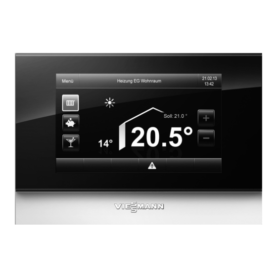
- Page 1 Viesmann Operating instructions for the system user Remote control unit and cascade controller VITOTROL 350-C Please keep safe. 5778 774 GB 2/2016...
- Page 2 Safety instructions For your safety Please follow these safety instructions closely to ■ Never remove casings. prevent accidents and material losses. ■ Never change or remove attachments or fitted accessories. Safety instructions explained Never open or retighten pipe connections. ■ Danger Danger This symbol warns against the risk of injury.
- Page 3 Safety instructions For your safety (cont.) In case of water leaking from the appliance Extractors Danger The operation of appliances that extract air to the out- Water leaking from the appliance poses an elec- side (cooker hoods, extractors, air conditioning units, trocution hazard.
- Page 4 Index Index 1. Introductory information Symbols ....................Terminology ................... Intended use ..................Commissioning ..................Permissible ambient temperature ............■ Energy saving tips ................. Tips for greater comfort ................. Central heating ................... ■ DHW heating ..................■ 2. Operation Controlsand symbols ................Programming unit default display ............
- Page 5 Index Index (cont.) 6. Local heating network Local heating network supply ..............25 supply Changing the max. flow temperature of the local heating network sup- ply ......................25 7. Solar energy ........................ 26 8. Cascade ........................ 27 9. Further adjustments Display settings ..................
- Page 6 Introductory information Symbols Symbol Meaning Reference to other document containing further information Step in a diagram: The numbers correspond to the order in which the steps are carried out. Warning of material losses and environ- mental pollution Live electrical area Pay particular attention.
- Page 7 These functions are not The Vitotrol 350-C can control up to 20 different cir- specifically identified. cuits. At the factory these circuits are each designated For questions relating to the available range of func- as a "Regulated circuit".
- Page 8 Introductory information Tips for greater comfort Central heating Standard room temperature ("Set room tempera- Heating curve ■ ■ ture") The heating curve enables you to individually adjust You can select your individual preferred temperature the heating system to the actual heat demand in your at any time in the standard menu.
- Page 9 Buttons for adjusting temperature Buttons for operating program Highlighted frame = active operating program Footer The Vitotrol 350-C programming unit is equipped with a touch sensitive display. To make settings and call up information, tap the on-screen buttons. Symbols in the display...
- Page 10 Operation Menu navigation Settings made via the default display Fig. 2 In the default display, you can call up and adjust the settings for the set regulated circuit as follows: ■ Heating mode "Heating mode is ON"/"Heating mode is OFF" Energy saving function ■...
- Page 11 Central heating Central heating settings If you require central heating, check the following ■ Have you set the correct operating program? points: ■ Have you set the required time program? Have you selected the heating circuit? ■ For setting see chapter "Heating circuit selection". ■...
- Page 12 Central heating Operating program (cont.) Default display Note 1. "Menu" Tapping è again shuts down heating mode. 2. "Central Heating" 3. Select the required heating circuit. 4. "Op mode" Fig. 6 5. Select the required operating program: ■ for heating mode è...
- Page 13 Central heating Time program (cont.) 4. "Heating time program" 7. Set the required switching times. 8. Press "OK" to confirm 9. Set further switching times or tap "OK" to confirm. Fig. 7 5. Select any day. Fig. 10 10. Select the days of the week when the new switch- ing times should apply.
- Page 14 Central heating Comfort function "Party mode" (cont.) Ending "Party mode" Party mode ends automatically after 8 hours. 3. Select the required regulated circuit. ■ 4. "Op mode" ■ Party mode ends automatically on changeover to the An operating program with a highlighted frame is "Standard"...
- Page 15 Central heating Energy saving function "Holiday program" (cont.) 5. Set the required departure and return dates. Fig. 11 6. Press "OK" to confirm The holiday program has the following effect: The rooms are heated to the set reduced room tem- perature (see page 11).
- Page 16 Central heating Heating curve (cont.) 4. "Temperature level diagram" Fig. 12 5. "Temp level questionnaire" Fig. 13 6. Make the required corrections. 7. Press "OK" to confirm Note Your input automatically changes the heating curve. Setting the heating curve via standard mode Default display 1.
- Page 17 Central heating Heating curve (cont.) 5. "Temperature level diagram" Fig. 15 6. Tap the required temperature button. Fig. 16 7. Correct the temperature with the +/- buttons. 8. Press "OK" to confirm Setting the heating curve via contractor mode Default display 1.
- Page 18 Central heating Heating curve (cont.) 5. "Temperature level diagram" Fig. 18 6. "Contractor mode" 7. Tap the "Slope" or "Level" buttons. Fig. 19 8. Correct the values with the +/- buttons. 9. Press "OK" to confirm You influence the heating characteristics by changing the slope or level of the heating curve. ■...
- Page 19 Central heating Heating curve (cont.) Heating characteristics Steps to take Example The living space is too cold during Adjust the heating curve slope to the next Slope spring/autumn, but warm enough dur- lower value and the level to a higher value. Level ing winter.
- Page 20 DHW heating Settings for DHW heating If you want DHW heating, check the following points: ■ Have you selected the required group? Have you set the required set DHW temperature? ■ Have you set the required time program? ■ DHW temperatures Changing the set DHW temperature Factory setting: 60 °C 3.
- Page 21 DHW heating Individual time program Default display 7. Select the time phase you want to change. 1. "Menu" 2. "DHW" 3. Select the required group if there are several. 4. "DHW time program" Fig. 25 8. Set the required switching times. 9.
- Page 22 DHW heating Operating status for DHW heating (cont.) 3. Select the required group if there are several. 4. If "DHW mode" is not enabled, tap "DHW mode". An operating program with a highlighted frame is 5. "OK" to confirm or wait a few seconds. already enabled.
- Page 23 Boiler operation Boiler menu Displaying the boiler overview Note The display depends on the type of boiler. Fig. 28 Fig. 29 The following is displayed: Buffer cylinder ■ ■ Fuel (if present) ■ Flue gas fan ■ Flow ■ Add boiler (if installed) ■...
- Page 24 Boiler operation Boiler menu (cont.) Symbols in the boiler operation menu Symbols are not permanently displayed but appear Example: according to the respective system version and the operating state. Fig. 31 Stopped function in manual mode Buttons: To enter settings. Note A menu in manual mode is identified on the overview To select automatic mode.
- Page 25 Local heating network supply Local heating network supply A local heating network supply bridges the distance to regulated circuits that are further away, for example in a neighbouring property. Several regulated circuits can be assigned to a local heating network supply, such as central heating and DHW heating of the neighbouring property.
- Page 26 Solar energy Solar energy If a solar regulated circuit has been configured for the boiler, solar energy information can be viewed (not for Vitosolic via KM BUS). Default display 1. "Menu" 2. Use to open the next overview screen 3. "Solar energy" 4.
- Page 27 Cascade Cascade Cascade default display Fig. 33 Fig. 34 Calls up the menu Status display for additional boiler Calls up the cascade menu Buffer cylinder temperature Date and time Information on buffer charging status Header To scroll to the left Boiler flow temperature Boiler number Boiler output indication...
- Page 28 Cascade Cascade (cont.) Boiler operating mode To set the boiler operating mode: 5. Select the required operating mode. 1. "Menu" No default output for boiler (boiler OFF) 2. "Cascade" Manually adjustable default output for boiler 3. "Op mode boiler" (boiler ON) 4.
- Page 29 Cascade Cascade (cont.) 3. "Boiler starting point" 4. Depending on the configuration, 2 to 4 starting points can be defined: Select a starting point. ■ Adjust the start value. ■ Setting range: 10 to 95 % Note The grey line shows the starting point of the optional additional boiler.
- Page 30 Further adjustments Display settings Setting the background brightness You would like to improve the readability of the menu 4. "Background illumination" text. For this, change the brightness of the display 5. Select the required illumination intensity. background. 6. Press "OK" to confirm Default display 1.
- Page 31 Further adjustments Display settings (cont.) 3. "Panel" 4. "Standby illumination" 5. "Panel switched off in standby" 6. Press "OK" to confirm Fig. 41 Briefly deactivating the display You can briefly lock the display, in order to clean the 4. "Screen lock" surface for example.
- Page 32 Further adjustments Display settings (cont.) Changing the delay for the idle screen If in standby mode no input is made on the screen 4. "Idle screen delay" after the expiry of the delay, the display changes over 5. Select the required setting. into idle mode.
- Page 33 Further adjustments Reinstating factory settings (cont.) Default setting Settings and values that are reset "Central Heating" Set room temperature: 20 °C ■ Reduced set room temperature ■ Time program for central heating ■ Heating curve slope and level ■ Comfort and energy saving functions ("Party mode", "Economy ■...
- Page 34 Calling up information Calling up information You can call up "Information" if you require additional Default display details. 1. "Menu" 2. "Information" 3. Select the required group. Calling up fault messages If your heating system develops a fault, symbol 3. You can acknowledge the cause of the fault with shown in the display footer in red.
- Page 35 Appendix Terminology System version Reduced heating mode The system version describes the components of your For periods when you are absent or during the night, heating system, such as a boiler, heating circuit pump, heat your rooms to the reduced room temperature. You mixer, valves, control unit, radiators, etc.
- Page 36 Appendix Terminology (cont.) Heating curve slope Outside temperature in °C Fig. 49 Setting of slope and level illustrated on a sample heating curve The heating curves shown apply with the following set- tings: Heating curve level = 0 ■ ■ Standard room temperature (set value) = 20 °C Slope Outside temperature in °C...
- Page 37 The several heating circuits. boiler control unit adjusts the heating circuit flow tem- The Vitotrol 350-C enables up to 20 heating circuits perature to the various conditions by means of a mixer, to be controlled ("Heating circuit 1", "Heating circuit e.g.
- Page 38 For example, the operating states for central heating named individually. are differentiated according to their different tempera- The Vitotrol 350-C enables the control of up to 20 ture levels. regulated circuits. The times at which the operating status changes are specified by you in the time program.
- Page 39 Appendix Information on disposal (cont.) Final decommissioning and disposal of the heating system Viessmann products can be recycled. Components and fluids from your heating systems are not part of ordinary domestic waste. Please contact your heating contractor in connection with the correct disposal of your old system.
- Page 40 Keyword index Keyword index Ambient temperature............7 Heating circuit............37 Heating circuit/cooling circuit........37 – Comfort..............8 Boiler operation symbols..........24 – Selecting..............11 Heating curve – Explanation............19, 35 Cascade..............27 – Level, changing............18 – Default display............27 – Slope, changing............18 Central heating.............9 Heating curve/cooling curve –...
- Page 41 Keyword index Keyword index (cont.) Reduced heating mode Terminology..............35 – Explanation............. 35 Time, setting...............32 Reduced room temperature........37 Time phases Regulated circuit............ 7, 38 – Central heating............12 Room temperature Time program – Comfort..............8 – Central heating............12 – Reduced..............37 – Comfort..............8 Room temperature-dependent........
- Page 44 Your contact Contact your local contractor if you have any questions regarding the maintenance and repair of your system. You may, for example, find local contractors on the internet under www.viessmann.com. Viessmann Werke GmbH & Co. KG Viessmann Limited D-35107 Allendorf...
Need help?
Do you have a question about the VITOTROL 350-C and is the answer not in the manual?
Questions and answers