Table of Contents
Advertisement
Installation and Service
Instructions
for use by heating contractor
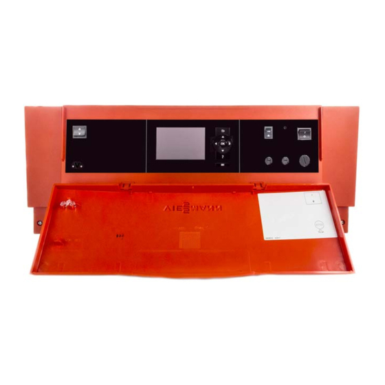
Vitotronic 300
Type GW2B
Weather-compensated, digital boiler control units
For use with Boiler models VD2A, VD2 and CT3
VITOTRONIC
Certified as a component
part for Viessmann boilers
5693 982 - 04 02/2015
300
r
Product may not be exactly as shown
IMPORTANT
Read and save these instructions
for future reference.
Please file in Service Binder
Advertisement
Table of Contents

Related Manuals for Viessmann VITOTRONIC300


Summary of Contents for Viessmann VITOTRONIC300
- Page 1 For use with Boiler models VD2A, VD2 and CT3 VITOTRONIC Product may not be exactly as shown IMPORTANT Read and save these instructions Certified as a component for future reference. part for Viessmann boilers Please file in Service Binder 5693 982 - 04 02/2015...
-
Page 2: General
Follow the by service personnel. Viessmann maintenance schedule of the boiler contained For a listing of applicable literature, in this manual. please see section entitled “Important Regulatory and Safety Requirements”. -
Page 3: Table Of Contents
Table of Contents Vitotronic 300, GW2B Installation and Service Page General Safety, Installation and Warranty Requirements....2 Product Information............2 Preparing for Installation Designations In The System Examples......6 System Example 1............7 Single boiler system with Therm-Control....7 Equipment required..........8 Electrical installation scheme........10 Mixing valve extension PCB........12 Required code............12 System Example 2............13 Single boiler system with shunt pump....13... - Page 4 Table of Contents Vitotronic 300, GW2B Installation and Service Page Installation Sequence Connections to Terminal ........44 Vitotronic 100, GC 1 with 30% LTP Package (VD2 only)..45 External Demand via Switching Contact.......46 External Demand via 0 - 10V Input......46 External Blocking via Switching Contact......47 External “Mixing Valve Closed”/“Mixing Valve Open”..48 External Changeover of Multi Stage/ Modulating Burners...........48...
- Page 5 Table of Contents Vitotronic 300, GW2B Installation and Service Page Designs Connection and Wiring Diagram, Type GW2B.....120 Components Sensors..............124 Outside Temperature Sensor.......125 Flue Gas Temperature Sensor......125 Extension Kit, Mixing Valve........126 Extension EA1 Accessory (optional)......127 Parts Lists Type GW2B............128 Specification Specifications............129...
-
Page 6: Preparing For Installation
Preparing for Installation Vitotronic 300, GW2B Installation and Service Designations in the System Examples In the following system examples, the Vitotronic 300, type GW2B, is used as the control unit. -
Page 7: System Example 1
Preparing for Installation Vitotronic 300, GW2B Installation and Service System Example 1 Single boiler system: Boiler with Therm-Control Hydraulic installation scheme Note: This scheme is a basic example without shut-off devices or safety equipment. This does not replace the need for professional planning on site. -
Page 8: Equipment Required
Preparing for Installation Vitotronic 300, GW2B Installation and Service System Example 1 (continued) Equipment required Pos. Description Boiler Vitotronic 300 GW2B Outside temperature sensor ATS Boiler water temperature sensor KTS Therm-Control temperature sensor ON/OFF switch (on site) DHW tank DHW tank temperature sensor STS DHW pump UPSB DHW recirculation pump ZP Heating circuit 2... - Page 9 Preparing for Installation Vitotronic 300, GW2B Installation and Service System Example 1 (continued) Equipment required Pos. Description Accessories Connection to safety equipment aBÖ (see page 43) Minimum pressure switch or limiter SDB Maximum pressure limiter SDB Water level limiter (low water cut-off) WB Central fault message system S Flue gas temperature sensor AGS Vitotrol 200A or Vitotrol 300A...
-
Page 10: Electrical Installation Scheme
Preparing for Installation Vitotronic 300, GW2B Installation and Service System Example 1 (continued) Electrical installation scheme Main PCB 120V... - Page 11 Preparing for Installation Vitotronic 300, GW2B Installation and Service System Example 1 (continued) Main PCB LV connections...
-
Page 12: Mixing Valve Extension Pcb
Preparing for Installation Vitotronic 300, GW2B Installation and Service System Example 1 (continued) Mixing valve extension PCB Wiring diagram Closing mixing valves installed downstream via temperature sensor T1 in heating systems with heating circuit control units that are not connected to the boiler control unit via LON. -
Page 13: System Example 2
Preparing for Installation Vitotronic 300, GW2B Installation and Service System Example 2 Single boiler system: Boiler with shunt pump for return temperature raising Hydraulic installation scheme Note: This scheme is a basic example without shut-off devices or safety equipment. This does not replace the need for professional planning on site. -
Page 14: Equipment Required
Preparing for Installation Vitotronic 300, GW2B Installation and Service System Example 2 (continued) Equipment required Pos. Description Boiler Boiler water temperature sensor KTS Vitotronic 300 GW2B Outside temperature sensor ATS Shunt pump BP Temperature sensor T2 - Contact temperature sensor - Immersion temperature sensor Temperature sensor T1 - Contact temperature sensor... - Page 15 Preparing for Installation Vitotronic 300, GW2B Installation and Service System Example 2 (continued) Equipment required Pos. Description - Contact temperature sensor - Immersion temperature sensor Mixing valve motor for flanged mixing valve M3 Accessories Connection to safety equipment aBÖ (see page 43) Minimum pressure switch or limiter SDB Maximum pressure limiter SDB Water level limiter (low water cut-off) WB...
-
Page 16: Electrical Installation Scheme
Preparing for Installation Vitotronic 300, GW2B Installation and Service System Example 2 (continued) Electrical installation scheme Main PCB 120V... - Page 17 Preparing for Installation Vitotronic 300, GW2B Installation and Service System Example 2 (continued) Main PCB LV connections...
-
Page 18: Mixing Valve Extension Pcb
Preparing for Installation Vitotronic 300, GW2B Installation and Service System Example 2 (continued) Mixing valve extension PCB Main Wiring diagram Closing mixing valves installed downstream via temperature sensor T1 in heating systems with heating circuit control units that are not connected to the boiler control unit via LON. -
Page 19: System Example 3
Preparing for Installation Vitotronic 300, GW2B Installation and Service System Example 3 Single boiler system: Boiler with shunt pump and 3-way mixing valve for return temperature control Hydraulic installation scheme Note: This scheme is a basic example without shut-off devices or safety equipment. This does not replace the need for professional planning on site. -
Page 20: Equipment Required
Preparing for Installation Vitotronic 300, GW2B Installation and Service System Example 3 (continued) Equipment required Pos. Description Boiler Boiler water temperature sensor KTS Vitotronic 300 GW2B Outside temperature sensor ATS Shunt pump BP 3-way mixing valve Temperature sensor T2 - Contact temperature sensor - Immersion temperature sensor Temperature sensor T1 - Contact temperature sensor... - Page 21 Preparing for Installation Vitotronic 300, GW2B Installation and Service System Example 3 (continued) Equipment required Pos. Description - Contact temperature sensor - Immersion temperature sensor Mixing valve motor for flanged mixing valve M3 Accessories Connection to safety equipment aBÖ (see page 20) Minimum pressure switch or limiter SDB Maximum pressure limiter SDB Water level limiter (low water cut-off) WB...
-
Page 22: Electrical Installation Scheme
Preparing for Installation Vitotronic 300, GW2B Installation and Service System Example 3 (continued) Electrical installation scheme Main PCB 120V... - Page 23 Preparing for Installation Vitotronic 300, GW2B Installation and Service System Example 3 (continued) Main PCB LV connections...
-
Page 24: Mixing Valve Extension Pcb
Preparing for Installation Vitotronic 300, GW2B Installation and Service System Example 3 (continued) Mixing valve extension PCB Required code 0C:1 “Boiler” group Constant return temperature control. 4E:1 “General” group Connection plug gS A1 motor for 3-way mixing valve for return temperature control. -
Page 25: System Example 4
Preparing for Installation Vitotronic 300, GW2B Installation and Service System Example 4 Single boiler system with Vitocrossal Hydraulic installation scheme Note: This scheme is a basic example without shut-off devices or safety equipment. This does not replace the need for professional planning on site. -
Page 26: Equipment Required
Preparing for Installation Vitotronic 300, GW2B Installation and Service System Example 4 (continued) Equipment required Pos. Description Boiler Vitotronic 300 GW2B Outside temperature sensor ATS Boiler water temperature sensor KTS Neutralizing system ON/OFF switch (on site) DHW tank DHW tank temperature sensor STS DHW pump UPSB DHW recirculation pump ZP Heating circuit 2... - Page 27 Preparing for Installation Vitotronic 300, GW2B Installation and Service System Example 4 (continued) Equipment required Pos. Description Connection to safety equipment aBÖ (see page 43) Minimum pressure switch or limiter SDB Maximum pressure limiter SDB Water level limiter (low water cut-off) WB Central fault message system S Flue gas temperature sensor AGS Vitotrol 200A or Vitotrol 300A...
-
Page 28: Electrical Installation Scheme
Preparing for Installation Vitotronic 300, GW2B Installation and Service System Example 4 (continued) Electrical installation scheme Main PCB 120V... - Page 29 Preparing for Installation Vitotronic 300, GW2B Installation and Service System Example 4 (continued) Main PCB LV connections...
-
Page 30: Mixing Valve Extension Pcb
Preparing for Installation Vitotronic 300, GW2B Installation and Service System Example 4 (continued) Mixing valve extension PCB Required code 0d:0 “Boiler” group Without Therm-Control temperature sensor. System Extension System versions where output sÖA1 is already used as a switching contact Use extension AM1 A (accessory). -
Page 31: Control Unit Installation
Control Unit Installation Vitotronic 300, GW2B Installation and Service Mounting the Control Unit 1. Fasten the metal backplate to the mounting surface with four fasteners. 2. Fasten the junction box to the backplate with two fasteners. 3. Install the control rear section to the junction box housing. -
Page 32: Fitting The Control Unit Front
Control Unit Installation Vitotronic 300, GW2B Installation and Service Fitting the Control Unit Front 1. Snap on the control cover to the control housing. 2. Snap on the interface cover to the control cover. 3. Release the stay bar and lock in position. 4. -
Page 33: Opening The Control Unit
Control Unit Installation Vitotronic 300, GW2B Installation and Service Opening the Control Unit 1. Remove the junction box cover screws and remove the cover. 2. Remove the front housing screws. 3. Swing up the front part of the control housing. 4. -
Page 34: Installation Sequence
Installation Sequence Vitotronic 300, GW2B Installation and Service Overview of Electrical Connections Extension for heating circuits 2 and 3 with mixing valve Main PCB 120V~ ? M2/M3 Supply temperature sensor sÖA1 Heating circuit pump sÖ M2/M3 Heating circuit pump gS M2/M3 Mixing valve motor Primary pump, primary store system (not used) Circulation pump, flue gas/water heat exchanger Main PCB, LV... - Page 35 Installation Sequence Vitotronic 300, GW2B Installation and Service Overview of Electrical Connections (continued) Legend A Vitotronic 300 GW2B B Junction box C Burner motor power supply (refer to page 53) fÖ Vitotronic 300 GW2B power supply...
-
Page 36: Pump Connection Overview
Installation Sequence Vitotronic 300, GW2B Installation and Service Pump Connection Overview Legend Pumps 120V A 120V pump output Available pump connections B To the Vitotronic control unit sÖM1/A1 Heat circuit pump C Junction box (switching contact/shunt pump) Boiler pump (shunt pump) Rated current: 2A~ DHW pump * Maximum output 6FLA shared between all... -
Page 37: Inserting Cables And Applying Strain Relief
Installation Sequence Vitotronic 300, GW2B Installation and Service Inserting Cables and Applying Strain Relief Legend A Cables with moulded strain relief B Restrain cables with zip tie to cable lead Inserting the Boiler Coding Card Only use the boiler coding card supplied with the boiler (see table in chapter “Components”). -
Page 38: Inserting The Lon Communication Module
Installation Sequence Vitotronic 300, GW2B Installation and Service Inserting the LON Communication Module Making the LON connection, see page 64. Legend A LON communication module (accessory) B Vitotronic 300 GW2B Adjusting the Fixed High Limit (if required) When adjusting the fixed high limit, the adjustable high limit and the electronic temperature limiter must also be adjusted (see chart below). -
Page 39: Changing The Adjustable High Limit (If Required)
Installation Sequence Vitotronic 300, GW2B Installation and Service Changing the Adjustable High Limit (if required) Note: Excessive DHW temperatures can damage the DHW tank. If the system is operated in conjunction with a DHW tank, ensure that the maximum permissible water temperature is not exceeded. -
Page 40: Power Supply
Installation Sequence Vitotronic 300, GW2B Installation and Service Power Supply 1. Ensure that the main power supply to the control Legend contains overcurrent protection with a minimum L: Line rating of 15A disconnect. N: Neutral G: Ground WARNING A Power supply 120VAC, 1PH, 60Hz, provide The control must be grounded. -
Page 41: External Connections
Installation Sequence Vitotronic 300, GW2B Installation and Service External Connections 120V pumps with an amperage draw of <2FLA Legend A DIN rail B Pump 120V pumps with an amperage draw of >2FLA Contactor specification 120VAC 1A Legend A DIN rail B Contactor/relay (field supplied) C Pump D Power supply w/disconnect and protection... -
Page 42: Connecting Actuators
Installation Sequence Vitotronic 300, GW2B Installation and Service Connecting Actuators Legend Legend A 24V Mixing Valve Adaptor A 120V Mixing Valve Adaptor B DIN Rail (in junction box) B DIN Rail (in junction box) C 24V Valve Actuator C 24V Valve Actuator D Valve D Valve 1. -
Page 43: Connecting The Central Fault Message Facility
Installation Sequence Vitotronic 300, GW2B Installation and Service Connecting the Central Fault Message Facility Rated voltage: 120V~ Rated current: max. 2A~ Connection of Low Water Cut-off Device 1. Remove jumper between terminals 12 and 15. 2. Make connection as shown in diagram. CAUTION The diagram shown is only a simplified conceptual drawing of a typical low water cut off (LWCO) device. -
Page 44: External Burner Blocking 150
Installation Sequence Vitotronic 300, GW2B Installation and Service External Burner Blocking Note: ‘Live’ contacts lead to short circuits or phase failure. The external connection must be floating. Remove jumper from DIN terminals 16 and 17. Note: Connect only safety shutdown equipment (dry contact), e.g. - Page 45 Installation Sequence Vitotronic 300, GW2B Installation and Service Vitotronic 100, GC1 with 30% LTP Package (VD2 only) 30% LTP Package consists of: Each pump output: 120V single phase - 1 circulation pump Max. pump current: 2 FLA - 1 cast iron flange set IMPORTANT - 2 full port ball valves - 1 flow check valve...
-
Page 46: External Demand Via Switching Contact
Installation Sequence Vitotronic 300, GW2B Installation and Service External Demand via Switching Contact Optional Connections: Connection H Plug aVH Note: ‘Live’ contacts lead to short circuits or phase H Extension EA1 (accessory, see page 127) failure. The external connection must be floating. Extension EA1 Plug aVH Legend... -
Page 47: External Blocking Via Switching Contact
Installation Sequence Vitotronic 300, GW2B Installation and Service External Blocking via Switching Contact Optional connections: Connection H Plug abÖ (See page 44) Note: ‘Live’ contacts lead to short circuits or phase H Plug aVD failure. The external connection must be floating. H Extension EA1 (accessory, see page 127) Extension EA1 Plug aVD... -
Page 48: External "Mixing Valve Closed"/"Mixing Valve Open
Installation Sequence Vitotronic 300, GW2B Installation and Service External “Mixing Valve Closed”/”Mixing Valve Open” Connection at plug aVD. Note: ‘Live’ contacts lead to short circuits or phase failure. The external connection must be floating. Legend A External “Mixing valve open” (floating contact) B External “Mixing valve closed”... -
Page 49: External Heating Program Changeover
Installation Sequence Vitotronic 300, GW2B Installation and Service External Heating Program Changeover Connection Optional Connections: H Plug aVD Note: ‘Live’ contacts lead to short circuits or phase H Extension EA1 (accessory, see page 127) failure. The external connection must be floating. Extension EA1 Plug aVD The changeover can be achieved separately for heating... -
Page 50: Connecting Of Combustion Air Device
Installation Sequence Vitotronic 300, GW2B Installation and Service Connection of Combustion Air Device Legend Connection of the Combustion Air Device Adaptor A Combustion Air Device Adaptor 1. Disconnect power to control and burners. B DIN Rail in connection enclosure 2. Install Combustion Air Device Adaptor, on DIN Rail inside connection enclosure (refer to installation manual of Combustion Air Device Adaptor). -
Page 51: Burner Connection, Burner Control Wiring
3. Connect the 7-pole plug fA and the 3-pole plug lÖ to the burner. CAUTION This is a generic connection drawing only! Follow the burner manufacturer’s connection drawings for Viessmann controls. Legend A To boiler control unit B To burner Terminal codes 1,2,3 Control circuit ”2nd stage burner or modulation... - Page 52 Vitotronic. Connect the burner in accordance with applicable codes. Note: Write the terminal numbers or markings on the drawing for future reference. Refer to burner manufacturer’s instruction on detailed connections for Viessmann controls. Legend A Vitotronic 300 GW2B B Burner fA Burner, 1st stage lÖ...
-
Page 53: Burner Connection, Motor Power Supply
Installation Sequence Vitotronic 300, GW2B Installation and Service Burner Connection, Motor Power Supply CAUTION The control must be grounded. Ensure that “L”, “N” and “G” are not interchanged. 1. Ensure that the main power supply to the control contains overcurrent protection with a maximum rating of 15A and 2 pole disconnect. - Page 54 See burner manual for correct fuse and wire gauge sizing, and specific connections for Viessmann controls. Disconnect power to burner and boiler control. Connect 240VAC power to the terminals 21, 22 and 23 on the DIN rail inside the connection enclosure.
- Page 55 BK1 and BK2 on the burner terminals. See burner manual for correct fuse and wire gauge sizing, and specific connections for Viessmann controls. 1. Disconnect power to burner and boiler control. 2. Connect 3PH power to the terminals 21, 22, 23 and 24 on the DIN rail inside the connection enclosure.
-
Page 56: Changing The Language
Commissioning Vitotronic 300, GW2B Installation and Service Changing the Language The following is displayed during commissioning (factory set German). Setting the Date and Time The time and date need to be reset during commissioning or after prolonged time out of use. Testing the High Limit Safety Cut-out The minimum circulation volume should be 10% of the circulation volume at rated load. -
Page 57: Matching The Coding Addresses To The System Version
“4d” “General” Function plug sL “4E” “General” Function plug gS “98” “General” Viessmann system number “9C” “General” Monitoring LON participants Matching the control unit to a two-stage burner Matching coding addresses according to the burner used Address Meaning Setting 03:... -
Page 58: Checking Actuator And Sensors
Commissioning Vitotronic 300, GW2B Installation and Service Matching the Coding Addresses to the System Version (continued) Matching the control unit to a modulating burner Note: The burner must be fully adjusted. To achieve a wide modulating range, set the minimum output as low as possible (take the chimney and flue system into account). - Page 59 Commissioning Vitotronic 300, GW2B Installation and Service Checking Actuators and Sensors (continued) Display Explanation “Burner stage 1” Burner stage 1 is switched on. “Full load” Mod. burner operates at max. output. “Burner stage 1 + 2” Burner stages 1 and 2 are switched ON. “Burner modulation”...
-
Page 60: Adjusting Heating Curves
Commissioning Vitotronic 300, GW2B Installation and Service Adjusting Heating Curves Settings in the factory set condition: Slope H Slope = 1.4 H Shift = 0 The heating curves illustrate the relationship between the outside temperature and the boiler water or supply temperature. - Page 61 Commissioning Vitotronic 300, GW2B Installation and Service Adjusting Heating Curves (continued) Selecting the set room temperature Individually adjustable for each heating circuit. The heating curve is offset along the axis of the set room temperature. When the heating circuit pump logic function has been enabled, it modifies the starting and stopping characteristics of the heating circuit pump.
-
Page 62: Connecting The Control Unit To The Lon
Commissioning Vitotronic 300, GW2B Installation and Service Adjusting Heating Curves (continued) Changing the slope and shift Extended menu: Individually adjustable for each heating circuit. 2. “Heating” 3. Select heating circuit. 4. “Heating curve” 5. “Slope” or “Shift” 6. Select heating curve according to the system requirements. - Page 63 Control unit receives the outside temperature outside temperature outside temperature Set code “97:2”. Set code “97:1”. Set code “97:1”. Viessmann system number Viessmann system number Viessmann system number Code “98:1” Code “98:1” Code “98:1” LON participant fault LON participant fault...
-
Page 64: Making The Lon Connection
Commissioning Vitotronic 300, GW2B Installation and Service Making the LON Connection The Viessmann LON system is designed for the “Line” BUS topology with a terminator at both ends (accessories). The transfer distances for LON are subject to the electrical properties of the respective cabling. -
Page 65: Calling Up The Service Menu
Service Scans Vitotronic 300, GW2B Installation and Service Calling up the Service Menu Service menu overview Press OK and simultaneously for approx. 4 sec. Service General Diagnosis Heating circuit 1 HC1 Heating circuit 2 HC2 Actuator test Heating circuit 3 HC3 Coding level 1 Solar Brief scan... -
Page 66: Scanning Operating Data
Service Scans Vitotronic 300, GW2B Installation and Service Scanning Operating Data Operating data can be scanned in six areas (see “Diagnosis” in the overview “Service menu”). Operating data on heating circuits with mixing valves and solar can only be scanned if the components are installed in the system. - Page 67 Service Scans Vitotronic 300, GW2B Installation and Service Brief Scan (continued) For an explanation of the relevant values in the individual lines, see the following table: Line (brief scan) Field System schemes 01 to 10 Control unit software version Programming unit software version 0 Burner Appliance identification type...
-
Page 68: Scanning And Resetting Service Display
Service Scans / Troubleshooting Vitotronic 300, GW2B Installation and Service Scanning and Resetting Service Display When the limits specified in the “Boiler” group have After a service has been carried out (reset service) been reached via coding addresses “1F”, “21” and “23”, 1. - Page 69 Troubleshooting Vitotronic 300, GW2B Installation and Service Fault Display (continued) Fault codes Displayed System characteristics Cause Measures fault code Control mode. Service “0F” is only Service required. displayed in the fault Note: After the service, set code “24:0” history. Controls as if the outside Short circuit, outside Check the outside temperature sensor temperature was 32°F (0°C)
- Page 70 Troubleshooting Vitotronic 300, GW2B Installation and Service Fault Display (continued) Displayed System characteristics Cause Measures fault code Mixing valve is being closed. Short circuit, supply Check the supply temperature sensor, heating temperature sensor circuit with mixing valve M3 (see page 124). (heating circuit 3) Mixing valve is being closed.
- Page 71 Troubleshooting Vitotronic 300, GW2B Installation and Service Fault Display (continued) Displayed System characteristics Cause Measures fault code With primary store system: Lead break, DHW tank Check the DHW tank temperature DHW tank heating is started and temperature sensor 2 sensor (see page 124). stopped by DHW tank temperature sensor 1.
- Page 72 Troubleshooting Vitotronic 300, GW2B Installation and Service Fault Display (continued) Displayed System characteristics Cause Measures fault code No solar DHW heating. Short circuit, collector temperature Check sensor at the solar control sensor, connection of temperature sensor unit (see separate installation and &...
- Page 73 Troubleshooting Vitotronic 300, GW2B Installation and Service Fault Display (continued) Displayed System characteristics Cause Measures fault code No solar DHW Lead break, DHW tank temperature sensor, Check sensor at the solar control heating. temperature sensor connection % at solar unit (see separate installation and control module.
- Page 74 Troubleshooting Vitotronic 300, GW2B Installation and Service Fault Display (continued) Displayed System characteristics Cause Measures fault code Control mode. Short circuit, flue gas temperature Check the flue gas temperature sensor sensor (see page 125). Control mode. Communication error, Check connections and replace the programming unit programming unit if required.
- Page 75 Troubleshooting Vitotronic 300, GW2B Installation and Service Fault Display (continued) Displayed System characteristics Cause Measures fault code Control mode. Incorrect LON communication module Replace LON communication module. No communication via LON. Boiler cools down. External safety equipment at plug abÖ Check connection and external safety equipment.
- Page 76 Troubleshooting Vitotronic 300, GW2B Installation and Service Fault Display (continued) Displayed System characteristics Cause Measures fault code Control mode. Communication fault, LON Check LON communication module No communication via communication module of control unit and replace if required. LON. If no LON communication module is installed, set code “76:0”...
-
Page 77: Boiler Water Temperature Control
Function Description Vitotronic 300, GW2B Installation and Service Boiler Water Temperature Control Functions Brief description The boiler water temperature is captured by the following H The boiler water temperature is regulated by starting equipment: and stopping the burner or through modulation. H High limit safety cut-out STB (liquid expansion) H The set boiler water temperature is determined from H Temperature controller TR (liquid expansion) -
Page 78: Function Description
Function Description Vitotronic 300, GW2B Installation and Service Boiler Water Temperature Control (continued) Switching hysteresis, burner Permanent switching hysteresis Code “04:0” Heat demand-dependent switching hysteresis The heat demand-dependent switching hysteresis takes Time the boiler load into account. The switching hysteresis, i.e. the burner runtime varies subject to actual heat demand. - Page 79 Function Description Vitotronic 300, GW2B Installation and Service Boiler Water Temperature Control (continued) Boiler protection functions Function Therm-Control The Therm-Control sensor, installed near the return connector, captures the return temperature. (Start-up system) The burner is ramped up to full load if the factory-selected H For heating systems with distributor installed close set temperature (defaulted by the boiler coding card) to the boiler.
- Page 80 Function Description Vitotronic 300, GW2B Installation and Service Boiler Water Temperature Control (continued) Return temperature raising in conjunction with heating Return temperature control via shunt pump and 3-way systems that are not connected with the Vitotronic via mixing valve For heating systems where downstream heating circuits Plug sÖA1 of the Vitotronic is used as switching contact.
-
Page 81: Heating Circuit Control
Function Description Vitotronic 300, GW2B Installation and Service Heating Circuit Control Brief description Room temperature In conjunction with the remote control and room H Type GW2B: temperature hook-up (coding address “b0” in the “Heating The control unit has control circuits for one heating circuit...”... - Page 82 Function Description Vitotronic 300, GW2B Installation and Service Heating Circuit Control (continued) Heating circuit pump logic (economy mode) System dynamics The heating circuit pump is switched off [set supply You can influence the control characteristics of the mixing temperature set to 32°F (0°C)] if the outside temperature valves via coding address “C4”...
- Page 83 Function Description Vitotronic 300, GW2B Installation and Service Heating Circuit Control (continued) Supply temperature control Differential temperature: The differential temperature is adjustable via coding address “9F” in the “General” group, factory set condition 8 K. The differential temperature is the value by which the common supply temperature should be higher than the highest currently required supply temperature of the heating circuit with mixing valve.
- Page 84 Function Description Vitotronic 300, GW2B Installation and Service Heating Circuit Control (continued) Example using the settings in the factory set condition Control sequence Mixing valve circuit The mixing valve motor will not be controlled within the “neutral zone” (±1 K). Supply temperature drops (Set value −1 K) The mixing valve motor receives the signal “Mixing valve...
-
Page 85: Dhw Tank Temperature Control
Function Description Vitotronic 300, GW2B Installation and Service DHW Tank Temperature Control Brief description Priority control H The DHW tank temperature control is a constant H With priority control: (code “A2:2” in the “Heating temperature control. This is the result of starting and circuit...”... - Page 86 Function Description Vitotronic 300, GW2B Installation and Service DHW Tank Temperature Control (continued) Control sequence Frost protection Code “55:0” in the “DHW” group, DHW tank heating The DHW tank will be heated to 68°F (20°C) if the DHW temperature sinks below 41°F (5ºC). The DHW tank goes cold (set value −2.5 K, adjustable via coding address “59”): Auxiliary function for DHW heating...
- Page 87 Function Description Vitotronic 300, GW2B Installation and Service DHW Tank Temperature Control (continued) Code “55:1” in the “DHW” group, adaptive DHW tank Code “55:3” in the “DHW” group, DHW tank temperature heating control, primary store system With adaptive DHW tank heating, the speed of the The DHW tank goes cold (set value −2.5 K, adjustable temperature rise during DHW heating is taken into via coding address “59”):...
-
Page 88: Calling Up Coding Level 1
Code 1 Vitotronic 300, GW2B Installation and Service Calling up Coding Level 1 Note: H The codes are displayed as plain text. H Codes that have no function, due to the heating system equipment level or the setting of other codes, are not displayed. -
Page 89: General" Group
Code 1 Vitotronic 300, GW2B Installation and Service “General” Group Coding Coding in the factory set condition Possible change System design 00:1 One heating circuit without mixing 00:2 For system schemes, see the following valve A1 (heating circuit 1), without table. - Page 90 Code 1 Vitotronic 300, GW2B Installation and Service “General” Group (continued) Coding in the factory set condition Possible change Servomotor runtime 40:... 40:5 Runtime adjustable from 5 to 199 sec. Runtime, isolation valve servomotor at plug gSA1. Factory set condition defaulted by boiler coding 40:199 card.
-
Page 91: Boiler" Group
Code 1 Vitotronic 300, GW2B Installation and Service “Boiler” Group Coding Coding in the factory set condition Possible change Burner Type 02:1 Two -stage burner 02:0 Single stage burner. 02:2 Modulating burner. Gas/oil operation 03:0 Gas operation. 03:1 Oil operation (irreversible). Burner curve 05:... -
Page 92: Solar" Group
Code 1 Vitotronic 300, GW2B Installation and Service “Solar” Group Only in conjunction with solar control module, type SM1. Coding Coding in the factory set condition Possible change Speed control solar circuit pump 02:0 Solar circuit pump (multi stage) without 02:1 Solar circuit pump (multi stage) is speed- speed control by solar control module SM1. -
Page 93: Heating Circuit 1", "Heating Circuit 2", "Heating Circuit 3" Group
Code 1 Vitotronic 300, GW2B Installation and Service “Heating Circuit 1”, “Heating Circuit 2”, “Heating Circuit 3” Group Coding Coding in the factory set condition Possible change Priority DHW heating A2:2 DHW tank priority applicable to heating A2:0 Without DHW tank priority applicable circuit pump and mixing valve. - Page 94 Code 1 Vitotronic 300, GW2B Installation and Service “Heating Circuit 1”, “Heating Circuit 2”, “Heating Circuit 3” Group (continued) Coding in the factory set condition Possible change Extended economy function mixing valve A7:0 Only for heating circuits with mixing valve: A7:1 With mixing valve economy function (extended Without mixing valve economy function.
- Page 95 Code 1 Vitotronic 300, GW2B Installation and Service “Heating Circuit 1”, “Heating Circuit 2”, “Heating Circuit 3” Group (continued) With heating circuit pump logic function: Parameter address b5:... Heating circuit pump “OFF” Heating circuit pump “ON” > RT + 5 K <...
- Page 96 Code 1 Vitotronic 300, GW2B Installation and Service “Heating Circuit 1”, “Heating Circuit 2”, “Heating Circuit 3” Group (continued) Coding in the factory set condition Possible change Slab curing function F1:0 Slab curing function disabled. F1:1 Not Used Do Not Adjust F1:6 F1:15 Not Used...
-
Page 97: Calling Up Coding Level 2
Code 2 Vitotronic 300, GW2B Installation and Service Calling up Coding Level 2 Note: H In coding level 2, all codes are accessible, including the codes from coding level 1. H Codes that have no function due to the heating system equipment level or the setting of other codes are not displayed. -
Page 98: General" Group
Code 2 Vitotronic 300, GW2B Installation and Service “General” Group Coding Coding in the factory set condition Possible change 00:1 One heating circuit A1 (heating circuit 1), 00:2 For system schemes, see the following table. without DHW heating. 00:10 Value address Designation 00: ... - Page 99 Code 2 Vitotronic 300, GW2B Installation and Service “General” Group (continued) Coding in the factory set condition Possible change 12:5 With extension EA1: 12:1 Runtime adjustable from 1 to 60 min. DHW recirculation pump runtime for brief operation: 5 min. 12:60 1E:0 With extension EA1 (analog input 0-10V):...
- Page 100 Code 2 Vitotronic 300, GW2B Installation and Service “General” Group (continued) Coding in the factory set condition Possible change 4d:1 4d:2 Boiler circuit pump. Connection at plug sL: Shunt pump. 4E:1 4E:2 Motor for 3-way mixing valve, primary store Connection at plug gSA1: system.
- Page 101 Code 2 Vitotronic 300, GW2B Installation and Service “General” Group (continued) Coding in the factory set condition Possible change 5E:0 Function input DE2 at extension EA1: 5E:1 Heating program changeover. No function. 5E:2 External demand with minimum set supply temperature. Set value selected in coding address “9b”...
- Page 102 Code 2 Vitotronic 300, GW2B Installation and Service “General” Group (continued) Coding in the factory set condition Possible change 78:1 LON communication enabled. 78:0 LON communication disabled. 79:1 With LON communication module: 79:0 Control unit is not fault manager. Control unit is fault manager. 7A:0 Without central control of heating circuits.
- Page 103 Code 2 Vitotronic 300, GW2B Installation and Service “General” Group (continued) Coding in the factory set condition Possible change 88:0 Temperature displayed in °C (Celsius). 88:1 Temperature displayed in °F (Fahrenheit). 8A:175 Do not adjust. 8F:0 Operation in the standard menu and extended 8F:1 Operation in the standard menu and extended menu enabled.
- Page 104 The control unit receives the outside temperature from the Vitotronic 200-H. 98:1 With LON communication module: 98:1 System number adjustable from 1 to 5. Viessmann system number (in conjunction with monitoring several systems via Vitocom 98:5 300). 99:0 99:1 No function.
- Page 105 Code 2 Vitotronic 300, GW2B Installation and Service “General” Group (continued) Coding in the factory set condition Possible change 9A:0 9A:1 No function. Connection at terminals 1 and 2 in plug aVD disabled (external “Mixing valve open”) 9A:2 External “Mixing valve open” (see page 48).
-
Page 106: Boiler" Group
Code 2 Vitotronic 300, GW2B Installation and Service “Boiler” Group Coding Coding in the factory set condition Possible change 02:1 Two -stage burner 02:0 Single stage burner. 02:2 Modulating burner. 03:0 Gas operation. 03:1 Oil operation (irreversible). Factory set condition specified 03:2 This occurs automatically, if an incorrect boiler by the boiler coding card. - Page 107 Code 2 Vitotronic 300, GW2B Installation and Service “Boiler” Group (continued) Coding in the factory set condition Possible change 0C:0 No function 0C:1 Constant return temperature control. Observe coding address “4E” in the group. 0d:1 With Therm-Control, controls the mixing 0d:0 Without Therm-Control.
- Page 108 Code 2 Vitotronic 300, GW2B Installation and Service “Boiler” Group (continued) Coding in the factory set condition Possible change 1F:0 With flue gas temperature sensor: 1F:1 When the flue gas temperature limit Flue gas temperature is not monitored for is exceeded, “Service” is displayed. service display.
-
Page 109: Dhw" Group
Code 2 Vitotronic 300, GW2B Installation and Service “DHW” Group Coding in the factory set condition Possible change 55:0 DHW tank heating, hysteresis ± 2.5 K. 55:1 Adaptive DHW tank heating enabled (see page 115). 55:2 DHW tank temperature control with 2 DHW tank temperature sensors (see page 116). - Page 110 Code 2 Vitotronic 300, GW2B Installation and Service “DHW” Group (continued) Coding in the factory set condition Possible change 66:4 Input of the set DHW temperature: 66:0 At the control unit programming unit. At the control unit programming unit and 66:1 At the control unit programming unit and remote all installed Vitotrol 300A remote controls.
-
Page 111: Solar" Group
Code 2 Vitotronic 300, GW2B Installation and Service “Solar” Group Only in conjunction with solar control module, type SM1. Coding Coding in the factory set condition Possible change 00:8 The solar circuit pump starts when the 00:2 The differential between the actual DHW collector temperature exceeds the actual DHW temperature and the start point for the solar temperature by 8 K. - Page 112 DHW tank temperature. 0b:0 Frost protection function for solar circuit 0b:1 Frost protection function for solar circuit switched off. switched on (not required with Viessmann heat transfer medium). 0C:1 Delta T monitoring switched on. 0C:0 Delta T monitoring switched off.
- Page 113 Code 2 Vitotronic 300, GW2B Installation and Service “Solar” Group (continued) Coding in the factory set condition Possible change 20:0 No extended control functions enabled. 20:1 Additional function for DHW heating. 20:2 Differential temperature control 2. 20:3 Differential temperature control 2 and auxiliary function.
- Page 114 Code 2 Vitotronic 300, GW2B Installation and Service “Solar” Group (continued) Coding in the factory set condition Possible change 25:50 Stop temperature for thermostat function 25:0 Stop temperature for thermostat function 122°F (50°C). is adjustable from 0 to 100 K. Start temperature for thermostat function 25:100 ≤...
-
Page 115: Heating Circuit 1", "Heating Circuit 2", "Heating Circuit 3" Group
Code 2 Vitotronic 300, GW2B Installation and Service “Heating Circuit 1”, “Heating Circuit 2”, “Heating Circuit 3” Group Coding Coding in the factory set condition Possible change A0:0 Without remote control. A0:1 With Vitotrol 200A; automatic recognition. A0:2 With Vitotrol 300A or Vitohome 300; automatic recognition. - Page 116 Code 2 Vitotronic 300, GW2B Installation and Service “Heating Circuit 1”, “Heating Circuit 2”, “Heating Circuit 3” Group (continued) Coding in the factory set condition Possible change A4:0 With frost protection. A4:1 No frost protection; this setting is only possible if code “A3:-9” has been selected. Note: Observe information regarding coding address “A3”.
- Page 117 Code 2 Vitotronic 300, GW2B Installation and Service “Heating Circuit 1”, “Heating Circuit 2”, “Heating Circuit 3” Group (continued) Coding in the factory set condition Possible change b0:0 With remote control: b0:1 Heating mode: weather compensated Heating mode/reduced mode: weather- Reduced mode: with room temperature compensated.
- Page 118 Code 2 Vitotronic 300, GW2B Installation and Service “Heating Circuit 1”, “Heating Circuit 2”, “Heating Circuit 3” Group (continued) Coding in the factory set condition Possible change C0:0 With remote control: C0:1 With stop optimization, max. setback time Without stop optimization. delay 1 h.
- Page 119 Code 2 Vitotronic 300, GW2B Installation and Service “Heating Circuit 1”, “Heating Circuit 2”, “Heating Circuit 3” Group (continued) Coding in the factory set condition Possible change E1:1 With remote control: E1:0 Set day temperature adjustable from 37.5 to Set day temperature adjustable at the remote 73.5°F (3 to 23ºC).
-
Page 120: Connection And Wiring Diagram, Type Gw2B
Designs Vitotronic 300, GW2B Installation and Service Connection and Wiring Diagram, Type GW2B Overview Legend PCB, extension for heating circuits 2 and 3 with mixing valve Boiler Coding card PCB low voltage A10 LON communication module (accessory) PCB 120V~ A11 Power supply unit PCB Programming unit A12 Programming unit ON/OFF switch Optolink PCB/emissions test switch... - Page 121 Designs Vitotronic 300, GW2B Installation and Service Connection and Wiring Diagram, Type GW2B (continued) PCB 120V~ Legend sÖ Heating circuit pump lÖ Burner stage 2/modulating abÖ External connections (remove jumper when Primary pump, primary store system connecting) a External safety equipment Circulation pump, flue gas/water heat exchanger b External blocking Safety chain (potential -free)
- Page 122 Designs Vitotronic 300, GW2B Installation and Service Connection and Wiring Diagram, Type GW2B (continued) PCB low voltage Legend Outside temperature sensor/radio clock receiver Flue gas temperature sensor § Boiler temperature sensor Supply temperature sensor, low loss header DHW tank temperature sensor aVD External hook-up DHW tank temperature sensor 2 for primary store aVG KM BUS participant...
- Page 123 Designs Vitotronic 300, GW2B Installation and Service Connection and Wiring Diagram, Type GW2B (continued) PCB, extension for heating circuits 2 and 3 with mixing valve Legend Supply temperature sensors Mixing valve motors Heating circuit pumps K1-K6 Relay sÖ Power supply Electrical interfaces fÖ...
-
Page 124: Sensors
H The room temperature sensor is connected at terminals 3 and 4 in the Vitotrol 300A. Installation and service instructions, Vitotronic 300A Viessmann NTC 10 kΩ (blue marking) 1. Pull corresponding plug. 2. Check the sensor resistance and compare it with the curve. -
Page 125: Outside Temperature Sensor
4. Depending on the result, replace the lead or the outside temperature sensor. Temperature Flue gas temperature sensor Viessmann NTC 20 kΩ (orange identification) When an entered limit in the Vitotronic 300 is reached (see coding address “1F” in “Boiler”) group, a service display appears. -
Page 126: Extension Kit, Mixing Valve
Components Vitotronic 300, GW2B Installation and Service Extension Kit, Mixing Valve Components: H Mixing valve motor, with 13 ft. (4.0 m) connecting cable (not for flanged mixing valve) H Plug for connecting the heating circuit pump H Flow temperature sensor as contact temperature sensor for recording the flow temperature, with 19 ft. -
Page 127: Extension Ea1 Accessory (Optional)
Components Vitotronic 300, GW2B Installation and Service Extension EA1 Accessory (optional) Duration of the heating program changeover Contact constantly closed: The changeover is active as long as the contact is closed. Contact only closed briefly via pushbutton: The changeover is enabled for the time selected in coding address “F2”... -
Page 128: Type Gw2B
Parts Lists Vitotronic 300, GW2B Installation and Service Type GW2B Ordering parts The following information is required: H Serial no. (see type plate A) H Position number of the part (from this parts list) Standard parts are available from your local supplier. Parts 0001 Hinge... - Page 129 Parts Lists Vitotronic 300, GW2B Installation and Service Type GW2B (continued)
-
Page 130: Specifications
Specification Vitotronic 300, GW2B Installation and Service Specifications Rated voltage 120V~ Rated frequency 60 Hz Rated current 2 x 6A Power consumption 10 W Protection class Permiss. ambient temperature H During operation 32 to 104°F (0 to +40°C) Installation in living spaces or boiler rooms (standard ambient conditions) H During storage and... - Page 131 Vitotronic 300, GW2B Installation and Service...
- Page 132 Vitotronic 300, GW2B Installation and Service...
Need help?
Do you have a question about the VITOTRONIC300 and is the answer not in the manual?
Questions and answers