Garmin Apollo GX 50 User Manual
Garmin gx 50: user guide
Hide thumbs
Also See for Apollo GX 50:
- Quick reference manual (4 pages) ,
- Installation manual (86 pages)
Table of Contents
Advertisement
Quick Links
Advertisement
Table of Contents

Related Manuals for Garmin Apollo GX 50


Summary of Contents for Garmin Apollo GX 50
- Page 2 Garmin AT, Inc. II Morrow, Garmin AT, Inc., and Apollo are trademarks of Garmin AT, Inc. © 2003 by Garmin AT, Inc. All rights reserved. Printed in the U.S.A. Garmin AT, Inc. Consumer Products Division 2345 Turner Road, S.E.
- Page 3 Welcome ... Welcome to a new era of aviation navigation. Once again, Garmin AT, Inc. has set new standards in features and ease of use for the general aviation public. The Apollo GX-series of products are unequaled in providing the features, level of performance, and reliability that aviation users require.
-
Page 4: Ordering Information
History of Revisions Revision Date January 1998 June 1998 January 1999 March 1999 July 2001 November 2001 August 2003 Ordering Information To receive additional copies of the Apollo GX50/55/60/65 manuals order the following part numbers: User’s Guide Approach User’s Guide Insert GX60/65 Comm User’s Guide Insert User’s Guide Binder (1") User’s Guide Binder (3/4”) -
Page 5: Important Notice
Connect the equipment into an outlet on a circuit different from the one the receiver is connected. • Consult the dealer or an experienced radio/TV technician for help. Changes or modifications to this equipment not expressly approved by Garmin AT, Inc. could void the user’s authority to operate this equipment. Canadian Notice This Class B digital apparatus meets all requirements of the Canadian Interference-Causing Equipment Regulations. - Page 6 Conventions concentric rotary knobs used to look at or change information on the display. When only the is shown next to an example, turn the concentric rotary knobs used to look at or change information on the display. The shows both of the concentric knobs. Turn the outer knob when this graphic is shown next to an example.
-
Page 7: Table Of Contents
Table of Contents Introduction ..........1-1 Apollo GX Features . - Page 8 GPS Position ........
- Page 9 Approach GPSS Operation ......3-38 GPSS Rules ........3-38 Tuned Station.
- Page 10 Table of Contents Fly Direct To A US Grid ......4-30 Create a User Waypoint By Basic Grid ....4-30 Fly Direct To A Basic Grid.
- Page 11 GPS Sensor ........
- Page 12 Table of Contents Encoding Altimeter ........7-20 Air Data Info.
- Page 13 Manually Selecting a Flight plan Leg ....9-19 Flight Plan Waypoint Sequencing ..... . . 9-20 Procedure Turns.
- Page 14 GPS Navigation ........
-
Page 15: Introduction
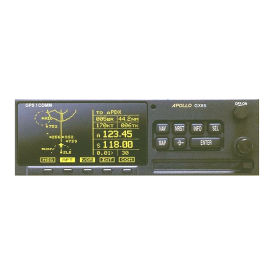
Introduction This guide describes the operation of the Apollo GX line of products. The GX50 and GX55 are GPS receivers. The GX60/65 models combine the GPS receiver with a VHF comm radio in a single package. Apollo GX Features The Apollo GX products are high performance GPS products with a high resolution moving map display configured in a 2 inch high by 6.25 inch wide... -
Page 16: Display
Nearest/Emergency Search feature, invented by II Morrow (Garmin AT), makes it easy to react to an emergency or change your active flight plan. GX55 The GX55 is designed to be simple slide-in, pin-compatible Apollo Loran and Flybuddy GPS receivers. -
Page 17: External Annunciators
Introduction External Annunciators When external indicators are installed, the Apollo GX will also provide an external indication when Parallel Track (PTK) is activated or a Message (MSG) is received. GX50/60 also have external annunciator controls for OBS/Hold and Approach Active. “Hold” refers to suspending waypoint sequencing. -
Page 18: Keys
Introduction Keys There are two types of keys that allow you access to the functions in your Apollo GX: permanent “hard” keys and displayed “smart” keys. Seven back lighted permanent keys are used to reach the functions or perform other operations of the Apollo GX. The “smart”... -
Page 19: Smart" Keys
Introduction MAP (Graphic Moving Map) The Map key starts the Moving Map function. The entire display is used as a graphic map display. DIRECT-TO key is used to define a direct course DIRECT-TO from your present position to a waypoint. Press once to select a waypoint. -
Page 20: Map Function Smart Keys
Introduction SYS (System Mode) Press the System mode is used to make system level adjustments and modify Nav function displays. SKIP (Start-Up Option) Press the SKIP bypass the start-up tests. This is for emergencies as the IFR tests must be completed to allow IFR flight. The Moving Map function uses several “smart”... - Page 21 Waypoint SCAN Key When the SCAN SCAN Moving Map display, turning the move between the nearest airports. You can then press to view information about that airport. In an INFO emergency press to the highlighted airport. Press the return the LARGE Map Setup Keys The Map Setup page displays three “smart”...
-
Page 22: Communications Radio Mode Smart Keys (Gx60/65)
Introduction Communicat The Recall (RCL), Monitor (MON), Memorize ions Radio (MEM), and Mode Smart the GX60/65 after the Keys (GX60/65) COM (GX60/65) Press the radio functions. Flip/Flop (GX60/65) Press the < > (left-most) and standby (right-most) frequency while in the Com function. You may use an optional external FLIP/FLOP control. - Page 23 Direct-To Nav Function Parallel Track Nearest Waypoint Search Internal Database of Airports, VORs, NDBs, Intersections, Frequencies, Airport Info, and controlled and special use airspace GPS Receiver Performance Specifications 8-Channel Parallel GPS Receiver Frequency Sensitivity (acquisition) Sensitivity (drop lock) Dynamic range...
-
Page 24: Apollo Gx Features
Electrical Input voltage 10 VDC to 40 VDC, reverse polarity protected Input current (GPS navigation input) 500 mA typical, 750 mA max at 13.75 VDC 250 mA typical, 375 mA max at 27.5 VDC Input current (comm input - GX60/65 only) 270 mA typical, 2A max at 13.75 VDC, receive... -
Page 25: Serial Interface
Serial Interface 2 RS-232 for GX50/60/65 1 RS-232 for GX55 Physical Specifications Height: 2.0 inches (5.08 cm) Width: 6.25 inches (15.88 cm) Depth: 11.125 inches (28.26 cm) behind panel, including mounting frame and connectors Weight (with mounting frame): GX50 and GX55 - 2.6 pounds (1.179 kg) GX60/65 - 3.1 pounds (1.409 kg) Environmental Specifications Operating temperature... - Page 26 Apollo GX Features VHF Comm Receiver Performance Specifications (GX60/65) Class D Frequency range - 118.000 to 136.975 MHz, 760 channels Sensitivity 1 microvolt (2 microvolt hard) for 6 dB S+N/N 30% modulation at 1000 Hz Selectivity <6 dB variation at ±22 kHz Speaker audio output level 12 watts into 4 ohms, 8 watts into 8 ohms Headphone audio output level...
-
Page 27: Getting Started
Getting Started This section explains how to get started using your Apollo GX. Information in this section explains how · Select a waypoint · Store waypoints · Find a Nearest Waypoint · Fly Direct-To a waypoint · Create a flight plan ·... -
Page 28: Sorting Waypoints By Selected Characters
Getting Started 2. The Waypoint Type will flash. Turn the knob to choose the Waypoint Type (Airport, VOR, NDB, INT, or USER). AIRPORT HIO PORTLAND city 3. Turn the character) to either the identifier or the city/facility name. Turn the character and show waypoints starting with that character. -
Page 29: Looking At All Waypoints In A Database
3. In this case we’ll keep the “A” as the second character. Turn the character and then turn the an “L.” AIRPORT 09C KALAMAZOO city dup MI USA 4. Now, press the “KALAMAZOO” flashes. AIRPORT 09C KALAMAZOO city dup MI USA 5. -
Page 30: Duplicate Identifier, City, Or Facility Names
Getting Started Duplicate Identifier, City, or Facility Names While performing Waypoint Identifier selection, you may see the word “dup” on the bottom line. This means that there is more than one waypoint for the displayed city or facility name. The same technique described above can be used to search for duplicate city and facility names. -
Page 31: Storing A Waypoint
Storing a Your Apollo GX can store up to 500 user-defined Waypoint waypoints in the USER database. The waypoint can be created by providing a Lat/Lon position or by a Radial and Distance from a reference waypoint. Then, you can give your waypoint a name and even include a runway length. -
Page 32: Finding A Nearest Waypoint
Getting Started Finding a When you press the Nearest search for the nearest 20 waypoints within 600 nm for Waypoint each waypoint type. You can also be selective about the runway length, lighting, and surface type. See Setting Runway Limits on page 3-12. 1. -
Page 33: Flying Direct-To A Waypoint
Flying Pressing Direct-To a changes to your TO waypoint. When you press Waypoint DIRECT-TO current TO waypoint in the Nav or Flight Plan functions or the waypoint displayed in the Database or Info functions. See page 3-31 for more details. 1. -
Page 34: Create A Flight Plan
Getting Started Create a You can create up to 30 flight plans with up to 20 legs Flight Plan each. A flight plan name can have up to eight characters using upper case letters, numbers, or a space. 1. Press Create a New Flight Plan page. -
Page 35: Activating A Flight Plan
5. The first flight plan leg page will be displayed. Press ______ to ______ 1 Press SEL 6. The Ins? prompt will flash. Press take you to the waypoint database. Use the ENTER Waypoint section starting on page 2-1. Press ENTER Ins? 7. -
Page 36: Using The Moving Map
Getting Started Using the The Moving Map gives you a graphic presentation of Moving your flight progress. You can select the type of waypoint displayed, a route line, ATC ring, airspace setup, type of airspace displayed, and map orientation. See the Moving Map section on page 4-1 for more details. - Page 37 Getting Started Knob SMALL Turn Knob LARGE Turn Knob LARGE Turn Knob LARGE Turn Knob LARGE Turn 2-11...
- Page 38 Getting Started Knob LARGE Turn Knob LARGE Turn Knob SMALL Turn Knob Knob LARGE Turn 2-12 SMALL Turn Knob LARGE Turn Knob LARGE Turn Knob LARGE Turn Knob LARGE Turn Knob LARGE Turn...
-
Page 39: Navigation Basics
See the Nav info section of the System Functions chapter (see page 7-1) for your options. The Nav functions: Nav pages, Parallel Track Offset, GPS Position, FROM/TO/NEXT Waypoints. The look at the pages available for each function; a diamond ( the display if more pages are available. -
Page 40: Autonav
Navigation Basics TAE = Difference between Track and Desired Track Bearing = Direction to waypoint Course = Desired Track between specific waypoints Desired Track = Course direction Track = Direction the aircraft is going Heading = Direction the aircraft is pointed Distance Off Track or Cross Track Deviation... -
Page 41: Relative Bearing Indicator
Relative The Relative Bearing Indicator is an arrow next to the Bearing Bearing value that indicates an approximate bearing Indicator to a waypoint or airspace relative to the aircraft’s current track when your current ground speed is more than 5 knots. The following illustration describes the bearing range for each arrow. -
Page 42: Estimated Time En Route (Ete)
00:00 to 99:59, and in seconds when less than one hour is displayed. If the ground speed is less than or equal to 5 knots, the GPS receiver does not have a valid position, or there is no TO waypoint, the ETE value will be shown as dashes. -
Page 43: Course Deviation Indicator (Cdi) And Distance Off Track
Course Deviation Indicator (CDI) and Distance Off Track The triangle symbol ( shows your position relative to being on-course. When the bar graph is to the right of the triangle, you must fly right to return on-course. In the example below, the bar graph indicates you are off-course to the right. -
Page 44: To/From Indicator
Navigation Basics If the GPS sensor is not sending a valid position, or the current TO waypoint is blank, the CDI will display “—Nav Flagged—”. TO/FROM Indicator The triangle symbol is also used as a TO-FROM indicator. When the triangle is facing up, you are on the “TO”... -
Page 45: Track (Trk) Angle
0 to 999 knots in 1 knot increments. The Ground Speed value will be replaced with dashes if the speed is less than 5 knots, there is no valid GPS position, or the TO waypoint is blank. See page 7-6 for details on changing units of measurement. -
Page 46: Minimum Safe Altitude (Msa)
“TO” waypoint with a 5 nm buffer around the course. The value will be replaced with dashes if there is no valid GPS position, the TO waypoint is blank, or the current position is outside of the 00:37 “... -
Page 47: Flight Time
Units are hours and minutes (00:00 to 23:59) based on the UTC 24 hour clock. The values will be replaced with dashes if the speed is less than 5 knots, there is no valid GPS position, or the TO and/or destination waypoints are blank. eta aEUG... - Page 48 Navigation Basics airport types you select, such as: runway length, lighting, and surface type. Press Nearest waypoint for more information about that waypoint. Starting Nearest Waypoint & Airspace Search 1. Press the NRST display the waypoint type or options: Airport, VOR, NDB, Intersection (INT), User (USER), Choose Reference Waypoint, Runway Limits, and Special Use Airspace.
- Page 49 2. The waypoint type will flash. Turn the to choose Airport, VOR, NDB, Intersection (INT) or User waypoint type. PORTLAND facil 3. Turn the LARGE name. The first character of the identifier will flash. Turn the SMALL LARGE change. AIRPORT SALEM city 4.
- Page 50 Navigation Basics Setting Runway Limits for Nearest Waypoints Narrow the type of airports that you will accept by choosing the runway length, lighting, and surface type. The Runway Limits selection also controls the airports that are displayed in the Map function. 1.
-
Page 51: Controlled Special Use Airspace
4. Turn the type to flash. Turn the the Hard, Soft, or Water surface types. Soft refers to grass, dirt, or gravel runways. Choices include: Hard, Hard/Soft, and Hard/Soft/Water. Runway Limits Ft:3500 Lit:Yes 5. Press ENTER to disable selection and to ignore any changes you have selected. - Page 52 Navigation Basics 1. Press the INFO airspace. Values for ceiling and floor may be any number of positive feet less than 100,000. Values may also be Unlimited, Ground, FL (Flight Level, followed by a number such as 050), Unknown, or NOTAM.
-
Page 53: Altitude Assist (Vnav)
In the Nav function, turn the Altitude Assist page. The diamond in the corner notes that turning the Altitude, Auto Descent, End Altitude, and Hold Altitude, and Buffer values. Altitude Assist Local Altimeter Setting 29.92" · Setting the Local Altimeter Value 1. - Page 54 Navigation Basics Setting Hold Altitude and Buffer The Hold Altitude is an altitude where you want to remain. The Buffer is the tolerance or range in altitude that you can move in vertically before a warning message is generated. Buffer 1.
- Page 55 Navigation Basics Auto Descent The Auto Descent feature allows you to input a desired End Altitude, an Offset Distance from a desired Auto Descent Waypoint from the Active flight plan, a desired Feet per Minute Descent rate, and an expected Ground speed. It then automatically calculates the distance remaining in your Active flight plan to the desired Auto Descent Waypoint and, based on the calculated glide path angle, your present...
- Page 56 Navigation Basics Set up your Auto-Descent by selecting: · Distance from destination waypoint (0 - 99 nm) or Offset Distance · Ending altitude (-1,500 - 50,000’ in 50’ steps) · Descent rate (100 - 5,000’/min in 10’/min steps) · Estimated ground speed (50 - 600 kts) 1.
-
Page 57: Parallel Track Offset
Navigation Basics Parallel This function allows you to create a parallel course Track Offset offset to the left or right from your current flight plan from 0.1 to 20.0 nm. You must have FROM and TO waypoints defined. Parallel Track cannot be activated if you set a course using Direct-To. - Page 58 Navigation Basics 1. In the Nav function, turn the display Parallel Track. Parallel Track Offset: Standby 2. Press available: Use or Standby. If Parallel Track is in use, “Standby” will flash. If Parallel Track is on Standby, “Use?” will flash. If the direction and ENTER distance values are what you want, press you want to change the direction or distance, turn...
-
Page 59: Gps Position
A PDOP value of 3 will provide a more reliable position fix than a value of 7. In the Navigation function, turn the display the GPS Position page. The PDOP value is shown in the lower, right corner (1.9 is shown here). GPS Position 44°10.11N PDOP... -
Page 60: Countdown Timer
Navigation Basics Countdown The Countdown Timer allows you to set a timer that Timer will alert you when it expires with a flashing MSG annunciator. The maximum time is 99:59:59 (hours, minutes, seconds). The default time on power up is the previous time that was entered. -
Page 61: Arc Assist
Arc Assist The Arc Assist function will help you to navigate along an arc. In the GX50/60, Arc Assist will help you fly approaches with DME Arcs. Arc Assist can be used as a user-defined arc to avoid special use airspaces, or for conducting aerial searches using increasingly larger circles. - Page 62 Navigation Basics 2. Press LARGE CORVALLIS facil 3. Select the Arc direction with the Left Arc dtk 171 ref: CVO Rad 005° 14.0nm· Rght Arc dtk 351 ref: CVO Rad 005° 14.0nm 4. Press ENTER navigating. The DTK on the Arc Assist page is the no-wind heading to hold the distance shown.
-
Page 63: Waypoint Distance Page
Waypoint This page shows the cumulative distance from your Distance current position to each waypoint in the active flight Page plan starting with the active leg. Turn the knob to view the next set of waypoints in your active flight plan. The waypoint type is shown to the left of the identifier. -
Page 64: From/To/Next Waypoint
Navigation Basics From/To/Next The FROM/TO/NEXT Waypoint allows you to Waypoint view and/or edit a three waypoint mini-flight plan, or view two legs of your flight plan, while within the Nav function. These waypoints are like a three waypoint window into your Active Flight Plan. Changes to the FROM/TO/NEXT page change the Active Flight Plan, and vice versa. - Page 65 2. Press select the FROM (first) waypoint position. Turn SMALL selection shows “Ins?” (Insert). Press ENTER From Ins? Next ______ 3. The Waypoint Type will flash. Choose the Waypoint Type with the AIRPORT APALACHIOCOLA city 4. Turn the waypoint name. The first character of the waypoint name will flash.
- Page 66 Navigation Basics 6. Turn the to the next character. Turn the select the desired character. Continue to select the needed characters. AIRPORT EUGENE city 7. Press ENTER waypoint. From EUG Next ______ B - Set the TO Waypoint 1. Press LARGE Press you did for the FROM waypoint.
- Page 67 C - Set the NEXT Waypoint 1. Press LARGE flash. Press waypoint as you did for the FROM and TO waypoints. ENTER From EUG Next Ins? 2. After selecting a NEXT waypoint, press ENTER From EUG Next HIO D - Editing FROM/TO/NEXT Waypoints 1.
-
Page 68: Placing The To Waypoint On Hold
Placing the TO Waypoint on Hold 1. Press LARGE on hold by pressing the external GPS/SEQ place a waypoint on Hold in the Flight Plan or FROM/TO/NEXT functions. The HOLD annunciator will light when it is installed to indicate that automatic waypoint sequencing is suspended. - Page 69 Using Pressing the Direct-To position as the FROM location. When using the Direct-To function, the FROM waypoint identifier is overwritten with the word “Direct.” If you remove the Direct-To position with the Del? option, the old FROM waypoint is returned to that position. If you edit the FROM position, Direct-To navigation will be replaced by the new entered waypoint.
-
Page 70: Direct-To Examples
Navigation Basics Direct-To Operation 1. Press the flash. AIRPORT PORTLAND city 2. Select the new destination (TO) waypoint using AIRPORT MC MINNVILLE city 3. Press ENTER Direct-To The following three examples provide some of the Examples more common ways that you can use the powerful Direct-To function. -
Page 71: Enter A New Waypoint Into A Flight Plan
1. You flew to the right to avoid a storm cloud and your CDI tells you to fly left, but you still have the same TO waypoint. Press current TO waypoint is displayed and the Waypoint Type will flash. AIRPORT SLE SALEM city 2. - Page 72 Navigation Basics 1. While on the first leg of your active flight plan, you find out that you need to make another stop on the way but you don’t want to change the rest of your plan. Press plan, turn the arpt 2.
-
Page 73: Direct-To Obs
Direct-To Pressing the desired track editor. OBS Desired Track allows entry of a desired track to or from the current TO waypoint. The current desired track in the navigation pages will be replaced by the OBS Desired Track value entered. You may also select the reference waypoint from your active flight plan. -
Page 74: Turn Anticipation
Navigation Basics 4. Press ENTER Turn The Apollo GX will provide information for you to Anticipation smoothly transition from one flight plan leg to another. Turns are drawn on the moving map. You will receive a message about ten seconds before the turn. -
Page 75: Wind And Turn Anticipation
GPSS GPS Steering (GPSS) information is provided by your Apollo GX when setup with a properly installed autopilot. An autopilot guided by information from your Apollo GX will be more accurate, faster responding, and smoother than using a CDI. -
Page 76: Approach Gpss Operation
Navigation Basics Approach GPSS Operation When the autopilot is directed by GPSS, there are few considerations when flying an approach. · GPSS information will not be provided after you pass the MAP. You need to follow the directions published on the approach plate. ·... -
Page 77: Tuned Station
Tuned When your Apollo GX is connected to and configured Station to communicate with an Apollo SL30 Nav/Comm, your Apollo GX will provide information about the VOR or Localizer tuned by the SL30. The Apollo SL30 with SW version 1.2, or later, sends the Tuned Station information once every second. -
Page 78: Tuning To A Localizer
Navigation Basics Tuning to a Localizer When the connected SL30 is tuned to a Localizer frequency, the SL30 sends the decoded Localizer identifier to the Apollo GX. The Apollo GX searches its LOC-DME database for an identifier match. If the Localizer is found to be a co-located LOC-DME, the Apollo GX will provide Distance, Speed, and Time information to the SL30 and for the Tuned Station... -
Page 79: Moving Map Functions
Moving Map Functions Press the and view the progress of your flight on a graphic display. Your present position, nearby waypoints, and special user-selectable. Three main pages are available in the Moving Map function: full screen map, split screen with map and Nav info, Search & Rescue (SAR) when selected, and map setups. -
Page 80: Controls
Moving Map Functions Special Use TO Waypoint Airspace Identifier Sector Route Line Waypoint Location Symbol Map Scale Controls LARGE function and selects waypoints when scanning. The SMALL Waypoint Type Keys The smart keys select the display of the waypoint types. The waypoint types selectable from the map view are: Airports, VORs, Intersections, User-defined, and NDBs. -
Page 81: Waypoint Scan Key
Waypoint Scan Key The Waypoint Scan smart key allows you to select an airport to get information about while viewing the map. 1. Press the SCAN 2. Turn the waypoint identifier. 3. Press INFO INFO Press INFO also press direct-to the highlighted airport. 4. -
Page 82: Map Setup
Moving Map Functions Special Use Airspace Route Line Your Present Position Cross Track Error Distance & Direction Map Setup The map setup function allows you to select the route line, map orientation, waypoint types that will be displayed, airspace type, and special use airspaces, as well as what airspace alerts will appear when an airspace is penetrated. -
Page 83: Map Orient
2. Turn the 3. Press ENTER ENTER turn the LARGE Map Orient The Map Orient selection allows you to choose how the top of the map display is oriented. North Up - The display is oriented so that vertical lines on the map are aligned with magnetic north. The aircraft symbol is centered in the display and will point towards the direction you are flying. -
Page 84: Map Reference
Moving Map Functions Map Reference The Map Reference selection allows you to choose either the Destination Waypoint (Dest) or your current position with an airplane icon (Plane) as the center point of the Moving Map display. 1. In the Map function, turn the the Map Setup page. - Page 85 Waypoints that are in an active flight plan will show up on the moving map even if its waypoint type is set as “Off.” 1. In the Map function, turn the the Map Setup page. Turn the Identifier & Waypoint Type page. Press editing the waypoint types.
-
Page 86: Track History
Moving Map Functions Track History Your Apollo GX can store a record of its progress in memory that will be shown on the display. The Track History is shown as a series of points on the display following the path of the plane icon. Track history may be recorded by time or by distance at a selected interval. - Page 87 Trk History:Off Save By:Distance Interval:0.5 2. Turn the SMALL 3. Turn the LARGE SMALL 4. Turn the LARGE SMALL chose to Save By Distance, select a distance between 0.1 and 10.0 nm. If you chose Save By Time, select a time between 1 sec. (00:01) and 10 minutes (10:00).
-
Page 88: Airspace Setup
Moving Map Functions Airspace Setup The Airspace Setup selections allows you to turn Airspace notification (Alerts) or map display of Airspaces On or Off, select the distance and time buffers for airspace alerts, turn ATC rings On or Off, and to choose the Airspace types that will be used. Airspace alerts will not be given during an approach. -
Page 89: Airspace Buffers
Airspace Buffers Three values may be adjusted for Airspace Buffers for determining CLOSE information: distance, elevation, and time. CLOSE distance may be from 0 to 99 nm at one nm intervals. Altitude values are from 0 to 9900 feet in 100 foot intervals. Time values are from 0 to 20 minutes in one minute intervals. -
Page 90: Atc Ring Selection
Moving Map Functions ATC Ring Selection When this choice is turned ON, a 5 nm radius artificial “ATC Ring” is drawn on the Map display around airports that have a control tower. From the Map Setup page, turn the to reach the ATC Ring selection page. 1. - Page 91 The Outer selection refers to the outline of the outside ring extended from the ground on up. Selecting Outer will be useful to VFR pilots who wish to avoid all airspaces. The sector selection refers to the outside edges of the sector from the ground on up unless you have altitude 3-dimensional information.
-
Page 92: Search And Rescue
Moving Map Functions Search and When activated, the Search and Rescue (SAR) feature Rescue allows a simplified, automated method of performing search patterns. The search patterns supported include parallel line, creeping line, and expanding square. A line showing the route of the pattern may also be displayed on the screen of your GX. -
Page 93: Grid Line Display
Grid Line Display While viewing the Search and Rescue (SAR) map page, you can choose how the grid lines are displayed. Press the Grid line selection options are slightly different for the two grid types, US and Basic. As you zoom out to approximately 40nm the grid lines will be removed. -
Page 94: Basic Grid Type
Moving Map Functions Basic Grid Type GRD – No grid lines GRD 1 – 60 minute grid lines GRD 2 – 30 minute grid lines GRD 3 – 15 minute grid lines Search and Rescue Map Setup Page The SAR Map Setup page provides selection of SAR Map (Off/On), Grid Type (US/Basic), and the Position (area of operation). - Page 95 4. Turn the knob to choose the position information. If you selected the US Grid type, choose the desired sectional name with the smart key. See the following Sectional Aeronautical Chart Grids table for the location nearest you operation. For the Basic Grid type, select the Position quadrant (NW, SW, NE, or SE) with the knob or the defined by the Equator, Prime Meridian, and the...
-
Page 96: Set The Sar Position (Basic Grid Type)
Moving Map Functions Set the SAR Position (Basic Grid Type) 1. If you selected the Basic Grid Type, you need to set the SAR Position. From the SAR Map Setup page turn the Position page. The SAR Position page only appears when the Basic Grid Type is selected. - Page 97 Sectional Aeronautical Chart Grids Chart Ident North Grid Limit Seattle 49 00N Great Falls 49 00N Billings 49 00N Twin Cities 49 00N Green Bay 48°15N Lake Huron 48 00N Montreal 48 00N Halifax 48 00N Klamath Falls 44 30N Salt Lake City 44 30N Cheyenne...
-
Page 98: Selecting A Pattern
Moving Map Functions Selecting A Pattern Three pattern types provide you with the ability to perform a search that best suits your needs. The three types include Parallel Line, Creeping Line, and Expanding Square. 1. While viewing the SAR Map page, press the (Pattern) smart key. -
Page 99: Parallel Line Search Pattern
Parallel Line Search Pattern The Parallel Line search pattern selection allows you to create a search pattern along parallel lines based on an established grid. Start Point · Select grid · Set spacing · Set direction · Activate pattern 1. While viewing the SAR Map page, press the smart key. - Page 100 Moving Map Functions 4. Use the desired Grid. 5. Turn the spacing. You may select between 0.2 and 9.9 nm. 6. Turn the option. Turn the Direction of Travel. You may select N/S or E/W. 7. Press ENTER ENTER 8. Press ENTER automatically return to the SAR Map page.
-
Page 101: Creeping Line Search Pattern
Creeping Line Search Pattern The Creeping Line search pattern is similar to the Parallel Line Search. The starting point is any selected waypoint, rather than a designated grid based on aeronautical sectionals. The creeping line search pattern will straddle the center of your flight path. You may select the following options: ·... - Page 102 Moving Map Functions 3. Press “INS?” (insert) or “CHG?” (change). Press to start editing the Starting Waypoint selection. ENTER Start: Ins? Spacing Direction :000· 4. Choose a waypoint using normal selection ENTER methods. Then, press 5. The Spacing option will flash. Turn the knob to select the desired pattern spacing.
- Page 103 9. Select the Leg Length. Press Leg Length. Turn the Length. You may select between 1.0 and 9.9 nm. Leg Length:5.0 Start:RIGHT Side 10. Turn the Turn the selection sets the side for the start of the search pattern. Center of Search Path Right Side Leg Length:8.0 Start:RIGHT Side...
-
Page 104: Expanding Square Search Pattern
Moving Map Functions Expanding Square Search Pattern The Expanding Square search pattern is similar to the Creeping Line Search. Rather than parallel lines, an expanding square is radiated from the Starting Waypoint according to the spacing between lines and at an angle selected for the Direction of Travel. You may select the following options: ·... - Page 105 3. Press . The Starting Waypoint field will flash “INS?” (insert) or “CHG?” (change). Press to start editing the Starting Waypoint selection. ENTER Start: Ins? Spacing Direction :000 4. Choose a waypoint using normal selection methods. Then, press ENTER 5. Turn the LARGE SMALL spacing.
-
Page 106: Mark A Position
Moving Map Functions Mark A Position When viewing the SAR Map page you may save a User waypoint to Mark a location of interest. Pressing the present position of the aircraft when you save the waypoint. 1. While viewing the SAR Map page, press 2. -
Page 107: Create A User Waypoint By Us Grid
Create A User Waypoint By US Grid This feature allows you to set a US Grid coordinate, such as the corner of a grid, as a User waypoint so you can fly Direct-To the starting point in a grid for flying a search pattern. -
Page 108: Fly Direct To A Us Grid
Moving Map Functions Fly Direct To A US Grid After creating a User waypoint for a US Grid, you can fly Direct-To, or set a flight plan to, the starting corner of that grid to begin a search pattern. 1. Press the User waypoint type, if necessary. - Page 109 If you want to fly to the Bravo-Charlie 3 corner of the 45°N and 123°W grid, you would define the corner as a USER waypoint with the name “53BC3.” The SAR position is set to 40°N and 120°W. º The “5” comes from the 5° added to 40°N. The next number, “3”, comes from the 3°...
-
Page 110: Fly Direct To A Basic Grid
Moving Map Functions 3. Press a User waypoint. 53BC3 USER 122°15.00W Fly Direct To A Basic Grid After creating a User waypoint for a Basic Grid, you can fly Direct-To, or set a flight plan to, the starting corner of that grid to begin a search pattern. 1. -
Page 111: Waypoint Database
Waypoint Database Waypoint The Apollo GX provides an extensive built-in Information database of waypoint information to aid the navigator. Waypoints in the database are divided into 5 categories. This structure allows you to easily select a waypoint as a destination, search for waypoint information, search for nearest waypoints, or insert waypoints into a flight plan. - Page 112 Waypoint Database · Sunrise/Sunset times · Waypoint comment VOR Waypoint Information · Identifier, name, state, & country · Radial and distance from the VOR · Bearing and distance from present position · · Operating frequency · Lat/Lon coordinates · Sunrise/Sunset time ·...
- Page 113 · Lat/Lon coordinates · Sunrise/sunset time · Waypoint comment USER Waypoint Information · Name/Identifier (User entered) · Lat/Lon coordinates (User entered) · Runway Length (User entered) · Bearing and distance from present position · · Sunrise/sunset time · Waypoint comment Getting You can access the Waypoint database by either Information...
- Page 114 Waypoint Database 3. Turn the waypoint name. The character will flash. Turn the SMALL AIRPORT EVERETT city 4. Turn the to the next character. Turn the select the desired character. Continue to select the needed characters. PORTLAND city 5. You can also select the waypoint by the facility name.
-
Page 115: Airport Info
7. Press INFO waypoint. AIRPORT PORTLAND-TROUTDA city 9. Press ENTER INFO Airport Info The Apollo GX database holds the most needed Pages information about each waypoint. The Airport information is described below. Similar information is available for each waypoint type. This information is shown after selecting the waypoint and pressing Home Page This is the page where the waypoint is selected from... - Page 116 Waypoint Database Bearing & distance from present position Turn the Distance from your present position. An arrow shows the Relative Bearing to the waypoint from your present position. ppos Bearing Distance Airport frequencies Turn the frequencies for the waypoint. In the GX60/65, the center three smart keys indicate the available frequencies.
- Page 117 Fuel Availability Turn the Available Fuel: Turn the and location. If the waypoint is an airport, the runway map will be shown. You can change the map scale by pressing again to disable map scaling. TO Waypoint Identifier Runway Numbers Map Scale Runway Info Turn the...
- Page 118 Waypoint Database Approach Info (GX50/60 only) Turn the approach. Lat/Lon Position Turn the Sunrise/Sunset Time Turn the time for the waypoint in UTC time. You can change the day and month to view alternate times by pressing and then using the Press 07 Nov utc time arpt...
-
Page 119: Create User Waypoint By Lat/Lon
Create User The Apollo GX allows you to create up to 500 of your Waypoint by own waypoints to the waypoint database. You can Lat/Lon create a waypoint based on a Lat/Lon or using a radial and distance from another waypoint. The starting Lat/Lon coordinates are your present position You can also add the runway length. -
Page 120: Create User Waypoint By Radial/Distance
Waypoint Database 4. Press ENTER waypoint information. HOME 122°51.52W 3000’ Create User A User waypoint may also be created where its Waypoint by position is referenced by a Radial and Distance from Radial/Distan another waypoint. 1. Press the the “Create User Wpt By Rad/Dis” page, and then press Create User Wpt ENTER... - Page 121 knobs to choose the identifier. After the SMALL reference waypoint name is chosen, press ENTER Ref Wpt: SLE 000.0° 000.0nm 5. The first character of the radial will flash. Now select the needed characters for the Radial and Distance. Turn the characters.
-
Page 122: Update User Wpt With Present Pos
Waypoint Database Update Update the Lat/Lon coordinates of an existing User User Wpt waypoint to your present position. You may also with change the name and other info for the waypoint. Present Pos 1. Press the 2. Turn the Waypoint” page. Press ENTER Update User Wpt 3. -
Page 123: Modify User Waypoint
3. Press ENTER Turn the Find Wpt to Del CABIN 4. When the waypoint to delete is displayed, press ENTER ENTER Modify User Waypoint 1. Press the “Modify User Wpt” page, and then press Modify User Wpt ENTER 2. Turn the Find WPT to Mod CABIN 3. -
Page 124: Creating Waypoint Comments
Waypoint Database 5. Turn the character. Continue using the change characters and the ENTER the desired character. After the correct characters are chosen, press Creating You may add comments to up to 200 waypoints. The Waypoint comments are added while viewing the Info for any Comments waypoint. - Page 125 Deleting You may delete any of the waypoint comments that Waypoint you have created. Comments 1. Press “Delete Waypoint Comment” page. Delete Waypoint Comment: 5 used 2. Press ENTER first waypoint comment page will show the waypoint identifier, waypoint type, and a portion of the comment.
-
Page 126: Update User Waypoint
Waypoint Database Update The Update User Waypoint function allows you to User change the position of an existing User waypoint to Waypoint your present position. 1. In the Database function, turn the “Update User Wpt With Ppos.” Then, press ENTER ENTER Update Usert Wpt 2. -
Page 127: Flight Plan Functions
Flight Plan Functions Flight plans are specific routes between waypoints you may store in the Apollo GX memory. This information is used to calculate useful flight statistics. The Flight Plan function allows you to have up to 30 stored flight plans. Each flight plan may have up to 20 legs. -
Page 128: Creating A Flight Plan
Flight Plan Functions Flight Plan pages. The active leg is the default page you will see when pressing *Active* Dest Wpt: PDT Active 2. Turn the a flight plan. Two asterisks indicate the active leg. arpt Active Flight Plan The first plan in the Flight Plan function is the Active plan and is noted by the name *Active* with asterisks. - Page 129 1. Press the the “Create a New Flightplan” page. Press SEL to Create a New Flight Plan 2. Press . The first character will flash. Turn the knob to select the first flight plan name SMALL character. R_______ Enter a New Plan Name 3.
- Page 130 Flight Plan Functions 7. Press prompt will flash. Press waypoint. ENTER Ins? 8. Turn the Turn the Turn the the waypoint identifier. AIRPORT EAGLE city 9. Turn the to the next character position. Turn the knob to select the next name character. AIRPORT EUGENE city...
-
Page 131: Flight Plan Sequencing
11. Repeat steps 7-10 for the remaining waypoints in your flight plan. ____ 12. Press SMALL Press changes. Press viewing the flight plan name page to activate or to choose other options. See the Flight Plan Options description on page 6-14 . Flight Plan The Apollo GX will automatically sequence from one Sequencing... -
Page 132: Flight Plan Leg Information
Flight Plan Functions Flight Plan Two types of information are available within flight plan legs: waypoint and flight information. Pressing Information INFO waypoint. Information about the ETA, ETE, Ground Speed, and Fuel is also available for each leg by selecting which option you like to view in the leg display. - Page 133 Estimated Time of Arrival is for the displayed TO waypoint and requires an actual ground speed of more than 5 knots. If there is no valid ETA for the leg, dashes will replace the value. to SLE 353° 48.0nm ETA 17:36 ETA? ETA? is the same as ETA, except the Estimated Ground Speed is used for the calculation.
- Page 134 Flight Plan Functions no valid ETE for the leg, dashes will replace the value. ETE? ETE? is the same as ETE, except the Estimated Ground Speed is used for the calculation. See Estimated Ground Speed on page 6-16 for more details. Fuel To? Fuel shows the amount of fuel required to get from the FROM waypoint to the TO waypoint for an...
-
Page 135: Manual Leg Activation
Direct-To If the leg page displayed is the currently active leg of the Active flight plan, and a Direct-To waypoint has been entered, the From waypoint will say “Direct.” The leg just prior to the currently active leg displays the leg as if the “Direct” waypoint did not exist. After sequencing, the “Direct”... -
Page 136: Flight Plan Editing
Flight Plan Functions Leg 2 Present Position WPT2 Leg 1 WPT1 (Departure WPT) Flight Plan You can alter any of the information you entered into Editing the flight plans. The editing options include: Chg?, Ins?, and Del? · Chg? - An existing waypoint can be changed if at least one valid waypoint exists in the database. - Page 137 Changing Existing Flight Plan Legs 1. In the Flight Plan function, turn the to a flight plan and then use the display the leg of the plan that you want to edit. 070° 23.0nm arpt 2. Press Chg? prompt. Turn the waypoint.
- Page 138 Flight Plan Functions 2. Press Ins? prompt. Turn the the waypoint you want changed. arpt 3. If another option was last used, turn the knob to choose Ins?. arpt 4. Press ENTER select the desired waypoint. AIRPORT PORTLAND city 5. After selecting the waypoint name, press ENTER arpt Deleting a Waypoint...
- Page 139 2. Press Chg? prompt. Turn the waypoint you want changed. arpt 3. Turn the arpt 4. Press ENTER plan leg will shift back to replace the deleted leg, i.e. after deleting leg 3, leg 4 will then become leg 3. arpt Before Deleting Leg Leg 3...
-
Page 140: Flight Plan Options
Flight Plan Functions Flight Plan In the Flight Plan function you may make changes to Options a flight plan. 1. In the Flight Plan function turn the a flight plan name page. 2. Press the available functions. 3. Press ENTER Activate Pressing displayed copies the selected inactive flight plan to the... -
Page 141: Rev Activate
Rev Activate Pressing when the “Rev Activate” option is ENTER displayed copies the selected flight plan to the active plan in reverse waypoint order and starts it at leg 1. Route 2 259nm Dest: Wpt: PDT Rev Activate? Reactivate Press when the “Reactivate”... -
Page 142: Copy Plan
Flight Plan Functions Copy Plan Pressing displayed allows you to copy any existing plan into the current plan, overwriting all of the current plan’s waypoints. You may choose the active or any inactive flight plan. 1. While viewing the desired flight plan, press then turn the option. -
Page 143: Clear Waypoints
Clear Waypoints Pressing will delete all waypoints in the ENTER selected flight plan. The plan name will remain. Route 2 259nm Dest: Wpt: PDT Clear Wpts? Reverse Flight Plan Pressing when the “Reverse” option is ENTER displayed reverses all the waypoints in the current flight plan. -
Page 144: Delete Plan
Flight Plan Functions plan or “Fuel To Uses Est Gr Speed” when the current flight plan is an inactive, stored flight plan. Delete Plan Pressing displayed deletes the current flight plan. The display returns to the previous flight plan’s name (or first) page. -
Page 145: Holding Patterns (Gx50/60)
3. Press ENTER ENTER Waypoint sequencing will be inhibited on the current leg. Pressing *Active* Dest: Wpt: PDT Holding Holding Patterns (GX50/60) A holding pattern is operationally the same as a procedure turn except that you usually intend to make repeated crossings of the waypoint on a specific inbound course. - Page 146 Flight Plan Functions selected inbound course and through the waypoint. The CDI will indicate “fly-left” if the aircraft is to the right of the desired track with reference to the selected inbound course. The CDI will indicate “fly-right” if the aircraft is to the left of the desired track with reference to the selected inbound course.
-
Page 147: Continue
with 020° inbound selected as the “OBS” course to UBG. "TO" Side If sequencing is enabled on the "TO" side of a line perpendicular to the destination waypoint, the flightplan will sequence to the "NEXT" waypoint when you cross the line. Continue The Continue option is available for the Active flight plan when the flight plan status is Holding (waypoint... -
Page 148: Load Approach (Gx50/60 Only)
Flight Plan Functions 3. Press ENTER Waypoint sequencing will be enabled. *Active* Dest: Wpt: PDT Active Load Approach (GX50/60 Only) This option is available for the Active flight plan when a datacard with approach information is inserted into the GX50/60. Press available approaches for the destination airport. -
Page 149: Enable Approach (Gx50/60 Only)
Enable Approach (GX50/60 Only) This option is available on the Flight Plan home page when an approach is already loaded, but not enabled, and you are within approximately 30 nm of the destination airport. Press approach. *Active* 56.1nm Dest Wpt: PDX Enable Approach? Disable Approach (GX50/60 Only) This option is available on the Flight Plan home page... -
Page 150: Saving An Active Flight Plan
Flight Plan Functions 1. While viewing the desired flight plan, press INFO Turn the Waypoint Comment 3. Press character. 4. Turn the to the next character position. Turn the knob to select the next comment character. GOOD RESTAURANT 5. After selecting the waypoint comment, press ENTER ENTER Saving an... - Page 151 2. Press knobs to enter a new plan name. After entering the name, press PLAN 9__ Enter a New Plan Name ENTER 3. Press ENTER ENTER twice to return to the Inactive Flight Plan name page. Don’t insert any waypoints. PLAN 9 Dest wpt: ——...
- Page 152 Flight Plan Functions An old navigation method 1. While holding your watch horizontal, point the hour hand at the sun. 2. Halfway between the hour hand and 12:00 is south. Don’t always depend on this method, but it is kind of fun.
-
Page 153: System Functions
System Functions Pressing the functions. After pressing the knob to view the available functions: Navigation Info, System Info, Position Sensors, Misc Sensors, and Comm Info (GX60/65 only). Press viewing the desired System function. Press Navigation System Info Info Navigation The Navigation Information function allows to make Information adjustments on the way information is shown in the Navigation function. -
Page 154: Navigation Mode Programmable And Autonav Pages
System Functions 1. While viewing the Autonav Time page, press Autonav Time: 4 Seconds/Page 2. Turn the Autonav Time: 7 Seconds/Page 3. Press ENTER 4. Press ENTER again to stop Autonav scrolling. ENTER Navigation Mode Programmable and Autonav Pages This function allows you to customize both the look of the programmable basic navigation pages and the selection of pages used in the Autonav function. - Page 155 4. Press flash. ete SLE 2.00 Dtk 353 48.0nm 5. Turn the information to be displayed in that field. GroundSp 100 kts 2.00 Dtk 353 48.0nm 6. Turn the edit. Turn the information. GroundSp 100 kts Trk 353 Dtk 353 48.0nm 7.
-
Page 156: Selecting Autonav Pages
System Functions Selecting Autonav Pages 1. While you are viewing a Nav page information page, press ENTER See page 7-5 for a listing of Nav Page choices. 2. You will be prompted to decide if you want to include this page in the Autonav scrolling. Turn 3. - Page 157 Nav Page Choices The following displays are available when customizing your Nav displays. Page references are shown in parentheses. Ete aUAO 02:27 Eta aUAO 00:02 Eta aCVO 00:22 Ft00:04 Trk 318 357 1.74 Â¥¨ 00:00 UTC --:-- to Descent ____’Above Hold EnrtSafeA 7700’...
-
Page 158: Setting Units Of Measurement
System Functions Setting Units of Measurement Nav displays that show distance may be selected to show either nautical miles, statute miles, or kilometers. 1. In the Navigation section of the System function, turn the Pages. Nav Mode Display Programmable and 2. -
Page 159: Magnetic Variation
Magnetic Variation Automatic or Manual Magnetic Variation can be set in this page. Automatic is the default setting on power-up, unless the database is invalid. Manually set Magnetic Variation to 0° to orient your navigation to True North. 1. In the Navigation section of the System function, turn the LARGE page and then press... -
Page 160: Flight Timer Trigger
System Functions Flight Timer Trigger The following procedure is used to edit the flight timer trigger speed. The flight timer may be set to start at power-up, or when the ground speed exceeds from 10 to 500 knots. The default (factory) setting is 60 knots. - Page 161 With the May Clear Direct-To Entry Option, the Direct-To waypoint will be inserted in the Active flight plan, and all of the other waypoints will be deleted from the Active flight plan, including approaches. With the Never Clears Direct-To option, the Direct-To waypoint is inserted before the current TO waypoint.
-
Page 162: Cdi Scaling
System Functions CDI Scaling The CDI Scaling option allows you to select manual or automatic full scale deflection of the internal CDI. Manual full scale deflection options include: 0.30 nm, 1.00 nm, and 5.00 nm. Automatic scaling will use 5.00 nm as the setting. -
Page 163: System Information
Date and Time 1. Press the the System Information function and press Turn the ENTER 2. This information is provided by the GPS satellites and you will not usually need to change it. Press flash. Date: 03 MAR 97 Time: 23:24 UTC 4. -
Page 164: Software Version
8. After completing your entries, press ENTER Software Version The Software Version function provides version information about the Apollo software, serial number, database, GPS sensor, display software. 1. In the System Information section of the System function, turn the Version page. Apollo GX-series SW Vers X.X... -
Page 165: Fuel Measure Units (Gx50/60 Only)
ENTER knob cw one click to view the SMALL x.xx knob cw one click to view the GPS SMALL knob to reach the Fuel LARGE to enable selection. Turn the System Functions... -
Page 166: Barometric Measure Units (Gx50/60 Only)
System Functions Barometric Measure Units (GX50/60 Only) This function allows you to choose the units of measure for the Local Altimeter Settings. The choices are inches (“) or millibars (MB). 1. In the System Information section of the System function, turn the Measure page. -
Page 167: Viewing Owner Information
2. Turn the Low. Press ENTER choice is kept until you change it. Viewing Owner Information The Owner Information function allows the user to enter their Name, Address, City, Phone, and Aircraft. As a security feature, the user must enter a password to enable editing of the Owner Information. -
Page 168: Editing Owner Information
System Functions Editing Owner Information It is necessary to enter a password before editing owner information. Editing is then enabled until the unit is turned off. 1. Start editing by pressing User Must First Enter Password.. 2. The password entry page is then ready. Select the characters with the next character to the right by turning the knob cw. -
Page 169: Gps Sensor
The GPS Sensor selection provides information about GPS satellite health, the GPS satellites available, information on each satellite, GPS Time, and GPS Reset. See the Introduction to GPS section on page 1 for more information on how GPS works. Healthy &... - Page 170 System Functions 3. Turn the Used for Position fixes page. SV means space vehicle, which is the same as a GPS satellite in this case. GPS SVs for Fix 28, 31, 27, 26, 19, 07, 02, 18 4. Turn the Satellite Status, Elevation, SNR, and Azimuth page.
- Page 171 GPS receiver. This forces a new search of the satellites. Use this function when it appears that the GPS receiver is locked up or seems to be taking far longer than it should to lock onto the signals.
-
Page 172: Miscellaneous Sensors
System Functions Miscellaneo The Miscellaneous Sensor section of the System us Sensors function Fuel/Air Data Sensor (F/ADS), fuel sensor, and altitude encoder when they are installed. The F/ADS includes a fuel sensor and altitude encoder. The F/ADS monitors fuel flow, air speed, outside air temperature/pressure, and magnetic heading. -
Page 173: Air Data Info
Air Data Info If the Air Data Sensor is installed, the following information is available. Air Speed True Airspeed - speed of the aircraft relative to the surrounding air speed. Indicated Air Speed - Speed of the aircraft as shown on the airspeed indicator. -
Page 174: Wind Direction And Speed
System Functions Wind Direction and Speed True Wind Direction, Magnetic Wind Direction, and the outside Wind Speed are displayed. Wind Dir 000°Tru Wind Dir 342°Mag Wind Spd Fuel Info An installed Fuel Data Sensor will provide the following information. Fuel Endurance ·... -
Page 175: Right Engine Fuel
Right Engine Fuel · Burn rate for the right engine in fuel units per hour · Amount of fuel used by the right engine since power up Right Engine Burn 17.7usg/hr Used 11usg Left Engine Fuel · Burn rate for the leftt engine in fuel units per hour ·... -
Page 176: Fuel Measure
System Functions Fuel Measure The GX50/60 allows you to choose the units of measure for your fuel displays. Fuel units may be displayed as US Gallons (USG), Imperial Gallons (IMG), Liters (L), Pounds (LBS), or Kilos (KGS). Press choose the desired units and then press ENTER 7-24 Fuel Measure... -
Page 177: Message Function
Message Function Message function is responsible for warning the user of changing conditions which require immediate attention. Press the message. Press the previous function. However, if a new message occurs, pressing until all new messages have been viewed. When a new message exists, the MSG annunciator flashes on and off approximately twice per second, until either the user views the new message, or the condition causing the message goes away. -
Page 178: New Messages
Message Function While any old message exists, the MSG annunciator remains steadily on at all times unless new messages arrive or all old message conditions go away. The home page in message mode is the first new message, if one exists, or the New Message Summary page if no new messages exist. -
Page 179: Messages
Messages The following is a summary of the conditions that cause a message warning, and examples of the messages generated for each condition. Special Use Airspace Messages Following is a list of the types of airspace messages which can be generated. All of the airspace messages become old messages after they are viewed. - Page 180 It becomes an old message after viewing. GPS Self Test Failure If the GPS self-test fails, a message displays indicating the cause of the failure in four hexadecimal digits. It becomes an old message after viewing. Empty To Wpt:...
- Page 181 Sensor Cannot Compute Lat/Lon GPS RAIM Not Available When RAIM detection is not available for the GPS sensor, a warning is generated. The current flight phase is displayed first (Terminal, En Route, or Approach). Approach warnings are for the GX50/60 only.
- Page 182 Message Function Communications GPS HDOP Position Error When the HDOP for the GPS sensor exceeds current flight phase HDOP requirements, a warning is generated and Nav data will be flagged as invalid. The current flight phase is displayed first (either Terminal or En route).
- Page 183 Altitude Input Approach RAIM Unavailable (GX50/60 Only) An approach is not valid unless RAIM is available. Abort Approach GPS RAIM Not Available RAIM Predict Too Late (GX50/60 Only) When the RAIM prediction occurs too close to the FAF, the following message appears.
- Page 184 Message Function Altitude Range Error When the altitude encoder reports an altitude that is out of range, the following message is created. Altitude Encoder Communications Failure This message appears when communications fail between the Apollo GX and the altitude encoder. Altitude Encoder Fuel/Air Data Sensor Communications Failure This message appears when communications fail...
- Page 185 Outside Hold Altitude Buffer You have gone above or below the selected Hold Altitude Buffer. Altitude Alert 500ft Above Hold Altitude Start Auto Descent Begin Descent To NOONS 500ft/min 130kts Arrival At Auto Descent Altitude Arrival At 2000ft Target Descent Altitude Arrival At The TO Waypoint The arrival message is generated when you are within 36 seconds of arrival at the current TO waypoint,...
- Page 186 Message Function Apollo GX with F/ADS Wind Info Arrival: SLE Next DTK Desired Hdg 324° In addition to the arrival waypoint identifier, the next leg’s desired track is shown when available; otherwise, it is dashed. If wind factors (from the Fuel/Air Data Sensor) and a next waypoint are available, the desired heading is also shown on line three;...
- Page 187 Holding at the TO Waypoint This form of the Arrival Alert is provided when holding at the current TO waypoint. Arrival: SLE - Holding - Next Leg is DME Arc This type of Arrival Alert is provided when the next TO waypoint is the end of a DME Arc holding at the current TO waypoint.
- Page 188 Message Function DME Arc Sequence (GX50/60 Only) This form of Sequence Alert is provided when the next TO waypoint is the end of a DME Arc in a nonprecision approach. Press directly to the NAV mode DME Arc Assist page. Sequence Alert DME Next-Use ARC Assist? Enter...
- Page 189 User Memory Failure This message indicates that one or more user settings were not within valid limits at power-up and needed to be reset. This message is cleared after the message is viewed. Memory Failure User Setups Have Been Reset Database Expired This message indicates that the datacard expiration date is before the current UTC date.
- Page 190 Message Function Low Internal Battery Voltage This message is generated when low internal battery voltage is detected. It becomes an old message after being viewed. Battery voltage is checked every 15 seconds. This battery backs up the memory for information added by the user, such as user waypoints and stored flight plans.
-
Page 191: Approach Basics (Gx50/60)
GPS approaches may overlay any type of non-precision localizer, LDA, and SDF approaches. GPS approaches may be either Phase II or Phase III overlay, or named GPS-only approaches. The major difference in the overlay approaches is that for a Phase... -
Page 192: Approach Transition
Approach Basics (GX50/60) Approach Transition Approach Transition operations occur after you enable approach operation. The APPRCH annunciator will turn on. The CDI sensitivity will gradually scale from 5.0 to 1.0 nm full scale per side automatically. The IAF is usually in the Approach Transition operation area. The ACTIVE annunciator will start flashing when you are within 3 nm inbound to the FAF and not on hold (sequencing suspended). - Page 193 Approach Basics (GX50/60) CAUTION The Apollo GX and the U.S. GPS Satellites use the World Geodetic System 1984 (WGS-84) horizontal datum for latitudes and longitudes. Approach plate or approach procedure data must be referenced to the WGS-84 or North American Datum 1983 (NAD-83) in order to use the approach.
- Page 194 Approach Basics (GX50/60)
-
Page 195: Approach Procedure
Approach There are three general types of Apollo GX operation: Procedure · En Route ü Load Destination Waypoint ü Load Approach Information · Approach Transition (or Approach Enabled) ü Enable approach (Method 1 or 2) ü 30 nm from Destination Airport ü... -
Page 196: Load A Destination Airport
Approach Basics (GX50/60) Load a Destination Airport The destination must be an airport. 1. Load your flight plan. You may activate or edit an existing flight plan. Press the FLIGHT PLAN mode. If the desired flight plan is active, go to the next section “Load Approach Information.”... -
Page 197: Load Approach Information
Load Approach Information 1. When a flight plan is active, press Nav function or the Moving Map to go directly to this display. In the Flight Plan function with the active flight plan displayed, press “Load Approach?” selection. *Active* 44.2nm Dest Wpt: PDX Load Approach? 2. -
Page 198: Approach Transition Operation (Enabling Approach)
Approach Basics (GX50/60) Approach Approach Transition Operation begins when you Transition enable an approach that has already been selected Operation from the database and loaded into the active flight (Enabling plan. The Approach annunciator will be on (and the Approach) Approach Active annunciator will be off) to indicate that your Apollo GX is operating in Approach Transition. - Page 199 the FAF if the approach has not yet been enabled. You will then get a message to enter the local altimeter setting. Enable Approach - Method 2 When an approach has been loaded, the aircraft is less than 30 nm from the destination airport, and the approach has not yet been enabled, pressing result in the “Enable Approach?”...
- Page 200 Approach Basics (GX50/60) Initial Approach Fix (IAF) 1. Prior to the Initial Approach Fix (IAF), the MSG indicator will light to announce a Waypoint Arrival Alert. Press view the instructions to the next approach point. CDI Scale Transitions 5.0 to 1.0nm 2.
-
Page 201: Approach Active Operation
APPRCH Annunciator On NOTE: If ACTIVE Annunciator is not Steady at FAF, do NOT Continue Approach Approach Approach Active Operation begins when you cross the Active Final Approach Fix (FAF) inbound if an approach Operation has been loaded and enabled, the FAF is the active waypoint, and there are no system-detected reasons not to continue the approach (see Message Mode starting on page 8-1). - Page 202 Approach Basics (GX50/60) Canceling the Approach will result in returning to Approach Transition operation. The Approach Active light will go out and the CDI will smoothly scale back to 1.0 nm sensitivity. Once Approach Active has been canceled by the pilot, it cannot be made active again except by again crossing the FAF inbound.
- Page 203 2. The OBS/HLD annunciator will remain lighted solid. CDI resolution is maintained at 0.3 nm. The To/From flag will switch from “TO” to “FROM” as you cross the MAP. 3. If desired, and conditions allow, land the aircraft. 4. If you do not choose to land, cancel the approach WPT SEQ by pressing the OBS/HLD...
- Page 204 Approach Basics (GX50/60) approach. You will now return to Approach Transition mode. The Approach Active light will go out and the CDI will gradually go back to Approach Transition CDI sensitivity (from 0.3 nm to 1.0 nm full-scale). As soon as you enable sequencing, the Apollo GX will sequence to the next waypoint in the flight plan.
-
Page 205: Canceling An Approach
OBS DTK: 151° to ROARK iaf brg 356 dtk 356 6. If you do not wish to hold or execute a procedure WPT SEQ turn at the next waypoint, press OBS/HLD sequencing at the active waypoint. You may also want to manually select a flight plan leg to intercept. -
Page 206: Repeating An Approach
Approach Basics (GX50/60) leg or waypoint and navigate to try the approach again. Your flight plan remains unchanged. After an active approach has been canceled, you cannot immediately reactivate it. The approach can only be reactivated by crossing the FAF inbound, when the FAF is the active waypoint. -
Page 207: Selecting A Different Approach
OBS DTK 159° UBG iaf brg 159 dtk 159 If you wish to intercept an approach leg, manually activate that leg. This is useful when receiving radar vectors back to intercept an approach leg. See “Manually Selecting a Flight Plan Leg” on page 9-19. Selecting a After a missed approach, you may want to select one Different... -
Page 208: Direct-To
Approach Basics (GX50/60) Direct-To The Direct-To function is used for several purposes. Especially during approach operations, you should be very comfortable with how this feature works. Review the Direct-To section on page 3-31 if you need a refresher before proceeding with approaches. If you select a waypoint that is not one of the waypoints already in the active flight plan, use of Direct-To will automatically unload any active... - Page 209 suspends leg-sequencing at that waypoint and lights the OBS/HLD annunciator. Subsequent pressing of the waypoint selection and OBS DTK choices. Manually Approach operations often result in the need to Selecting a manually select a leg of the active flight plan. Manual Flight plan leg selection will often be required when operating with Radar vectors and there is the need to intercept...
-
Page 210: Flight Plan Waypoint Sequencing
Approach Basics (GX50/60) Flight Plan A flight plan will sequence to the next leg of the flight Waypoint plan as the aircraft crosses to the bisector that runs Sequencing through the “TO” waypoint. The bisector is defined as the angle that is half of the angle between the current leg and the next leg. -
Page 211: Procedure Turns
Procedure A procedure turn is a way of crossing the same Turns waypoint more than once in order to accomplish a course reversal. First, make sure that flight plan leg sequencing is suspended. Second, after crossing the waypoint, set the correct inbound course to intercept. Finally, enable sequencing when you are established inbound. -
Page 212: Procedure Turn At Faf
Approach Basics (GX50/60) 2. Set the desired inbound course with the SMALL ENTER OBS DTK: 000° to brg 000 dtk 000 3. Verify that waypoint sequencing is set to “auto.” 4. Fly the procedure-turn or course reversal and intercept the selected inbound course. While flying outbound, the CDI is reverse sensing. - Page 213 are less than 2 nm from the FAF when you enable sequencing, then transition to Approach Active, i.e., the CDI sensitivity will begin changing to 0.3 nm full-scale deflection immediately. The approach annunciator will begin flashing immediately if all the conditions exist to allow the approach to go to the active condition (RAIM available, etc.).
-
Page 214: Holding Patterns
Approach Basics (GX50/60) Holding A holding pattern is operationally the same as a Patterns procedure turn except that you usually intend to make repeated crossings of the waypoint on a specific inbound course. Like the procedure turn, the steps will always be: ·... - Page 215 You must be inbound and have sequencing enabled to allow proper transition to Approach Active at the FAF. This example shows holding at the FAF, SL (TURNO) for the NDB or GPS Runway 31 Salem (McNary) Airport (SLE). Salem RW31...
-
Page 216: Dme Arcs (Arc Assist)
Approach Basics (GX50/60) DME Arcs DME-Arcs are usually used as a method for pilots to (Arc Assist) intercept a flight plan leg, or a course to a fix. They are sometimes used as a method for reaching a subsequent fix such as a missed approach holding waypoint. -
Page 217: Vector To Final
The desired track shown on an Arc Assist page is relative to the arc, not to the flight plan legs. The DME-Arc is always perpendicular to the present radial and it shows the desired track at the current radial if the aircraft was on the arc. It is the desired no-wind heading if established on the arc. -
Page 218: Navigating To A Dme
Approach Basics (GX50/60) 3. The Course Intercept alert will appear as you become established inbound on the final approach course. Course Intercept Next Dtk Navigating The Apollo GX may be used to help guide you to to a DME near the start of an ILS approach by using the location of a DME as a destination waypoint. -
Page 219: Raim
Approach Basics (GX50/60) RAIM RAIM stands for Receiver Autonomous Integrity Monitor. It is a way a GPS receiver can verify when the signals it is receiving from one or more of the satellites are useable. It does this by using more satellites than are required for a position solution. - Page 220 Approach Basics (GX50/60) to predict whether RAIM will be available at the estimated time of arrival at the destination. Your Apollo GX provides you with a RAIM prediction page. This page allows you to determine if RAIM should be available at any location and time. If it says RAIM will be available, it actually means that it will be available at your predicted time of arrival and plus and minus 15 minutes from your arrival time...
- Page 221 What you have lost is the ability to tell if a satellite is sending bad data. For all operations except Approach, the FAA has determined that it is acceptable for you to continue to use GPS for IFR 9-31...
- Page 222 When a satellite fails, even if that failure is detected by an earth-based monitoring station, it can be some time before an uplink to that satellite can occur. During that time, there is no way for a GPS receiver to know that the information from that satellite is bad 9-32...
-
Page 223: Raim Nav Page (Gx50/60 Only)
directly from that satellite’s transmissions. An integrity monitor, such as RAIM when it is available, protects you from false or misleading navigation displays resulting from bad satellite information. RAIM Nav The Apollo GX50/60 allows you to manage your Page RAIM prediction process, besides allowing for (GX50/60 automatic prediction. - Page 224 Approach Basics (GX50/60) 4. Press Press now. The top line will display the result of the ENTER calculation of whether RAIM is available or not available. Excluding Satellites The Apollo GX50/60 allows you to specify satellite outages for RAIM predictions using information from NOTAMs or NANUs.
-
Page 225: Clear Waypoints
Clearing the Exclusion List You can also easily clear the Exclusion List. 1. While viewing the RAIM home page, press The “Predict RAIM?” choice will flash. Turn the SMALL Clr Ignore List? at: SLE 10Nov97 22:06 · 2. Press ENTER Emergency In the case of an emergency, alternate, or a sudden (Alternate) -
Page 226: Fly Direct-To A Nearest Airport
DIRECT-TO ENTER OR USA . The Load Approach option will appear. 0.0nm Load Approach? . Now, turn the ENTER APPR GPS 17 INNOP iaf ACVOL faf RW17 SHEDD mahp Scale 19nm knob to SMALL . You have now set a... -
Page 227: Approach Examples
Approach Examples This section expands on the previous Approach Basics section. A variety of the situations that you may encounter while using approaches is included in this section. Use this section to familiarize yourself with the procedures that you expect to use in normal flight operations. - Page 228 Approach Examples Reproduced with permission of JeppesenSanderson Inc. Reduced for illustrative purposes. 9-38...
-
Page 229: Approach Example 1 - Straight In
Example 1 - Idaho. This example was selected because it is a new Straight In approach designed especially for TSO C-129 GPS equipment. It is probably as simple an approach to fly with the Apollo GX as there is. It is good planning to always consider what... - Page 230 DEFKI (FAF) RW11 (MAP) NEMEW (MAHP) En Route Load and activate your flight plan, then load the approach. Select the Nampa Municipal GPS Rwy 11 approach. 30 nm From Nampa Municipal Airport 1. The message annunciator will flash. Press then...
- Page 231 2. The Approach Active annunciator will begin flashing 3 nm from DEFKI (FAF) indicating that approach RAIM prediction is beginning. The transition to approach active is starting. 3. At 2 nm from DEFKI the CDI scale will begin changing from 1 nm to 0.3 nm full scale deflection. Point C (Between DEFKI and RW 11) As you cross DEFKI, verify that the Approach Active and OBS/HLD annunciators are on steady.
- Page 232 Approach Examples 9-42...
- Page 233 Approach Examples Reproduced with permission of JeppesenSanderson Inc. Reduced for illustrative purposes. 9-43...
-
Page 234: Approach Example 2 - Holding At Ifaf
Approach Examples Approach This example uses an active flight plan ending at the Example 2 - Medford, Oregon airport (MFR). The last two Holding at waypoints in this example are the Klamath Falls, IFAF Oregon VOR (LMT) and the Medford airport. This approach example involves a procedure turn, a combined IAF and FAF (IFAF), and a MAHP holding pattern at the FAF. - Page 235 2. Activate the flight plan. Press knob to display the “Example 2” flight plan. Press and then ENTER 3. Load the VOR or GPS-A approach to MFR. In Nav or Flight Plan modes, press flash “Load Approach?” Press ENTER A:OED” with the...
- Page 236 Approach Examples Point A (Inbound to OED from the east) 1. Flight plan sequencing at OED is disabled because it is an IFAF in preparation for a procedure turn. The combined IAF/FAF waypoint is noted on your Apollo GX as IFAF. 2.
- Page 237 Point D (Inbound to OED) 1. As you intercept the 162 inbound a course intercept alert is given. Sequencing is automatically enabled. Turn to intercept the desired course. At 3 nm inbound to OED, the Approach Active annunciator will begin flashing to indicate that approach RAIM prediction is beginning.
- Page 238 Approach Examples 3. Because OED is the MAHP, it is automatically a Hold waypoint and flight plan sequencing is suspended. Verify that the OBS/HLD annunciator is lighted. Point G (At the MAHP) 1. Upon crossing OED, press ENTER to set the inbound holding course (153°). Use the LARGE ENTER ENTER...
- Page 239 Approach Examples Reproduced with permission of JeppesenSanderson Inc. Reduced for illustrative purposes. 9-49...
- Page 240 Approach Examples 9-50...
-
Page 241: Approach Example 3 - Missed Approach
Approach This approach example describes an NDB approach Example 3 - from PARMO (IAF) to the Boise, Idaho airport Missed (BOI). This example was chosen primarily because of Approach the unusual published missed approach instructions and to illustrate how to navigate this missed approach with the Apollo GX. - Page 242 Approach Examples 3. Load the NDB approach to BOI. In flight plan mode active plan or Nav mode home page, press ENTER ENTER SMALL PARMO (IAF) ENTER nBO (FAF & MAHP) 30 nm from Boise (BOI) 1. At 30 nm from your destination, the MSG annunciator will light.
- Page 243 2. Now press knob to reach the reference waypoint. Turn the knob to select BO. SMALL OBS DTK: 150° to ENTER brg 162 dtk 162 3. Turn the Select 105° with the inbound course. Press ENTER indicate FROM and will provide guidance on the 105° outbound bearing as per missed approach instructions.
- Page 244 Approach Examples Reproduced with permission of JeppesenSanderson Inc. Reduced for illustrative purposes. 9-54...
- Page 245 Approach Examples 9-55...
-
Page 246: Approach Example 4 - Vor Reference
Approach Examples Approach This example for the VORDME A:MUGGZ Example 4 - approach uses a flight plan with the last two waypoints as VOR IMB (Kimberly, Oregon) to The Reference Dalles, Oregon (DLS). This example is illustrates the following points: the step down fixes are referenced to a VOR that is not co-located with the MAP, the nature of the published missed approach instructions, and a DME Arc is part of the approach. - Page 247 En Route 1. Create a flight plan named “Example4” with Kimberly VOR (IMB) as the last waypoint before The Dalles, Oregon (DLS) as the destination airport. 2. Activate the flight plan. Press knob to display the “Example4” flight plan. Press , turn the then press ENTER...
- Page 248 Approach Examples 2. If the reference VOR is LTJ, press ENTER reference is not LTJ, press VOR with the press provide guidance with the Arc Assist and Map ENTER pages. Arc Assist Ref: LTJ Press ENTER/SEL 3. Use the Arc Assist page as the primary guidance for flying the DME Arc.
- Page 249 Point C - Inbound between D1850 (ARC) and CF005 (APPR) 1. Flight plan sequencing will operate automatically for each of the remaining waypoints. You will receive arrival and next DTK messages as you cross each waypoint. Press Press again to return to the previous display. Point D - Between CF005 (APPR) to FF005 (FAF) 1.
- Page 250 Approach Examples Point F - Turning to intercept 165° to MUGGZ (MAHP) 1. When you reach the Missed Approach Point and WPT SEQ you wish to fly the published Missed Approach OBS/HLD procedure, press sequencing as you start your climbing right turn. 2.
- Page 251 Approach Examples Manual You are flying a section of an active flight plan from Flight Plan SLE to BTG to OLM. As you approach the Portland Leg Selection area, you are given Radar vectors to the West of your Example course.
- Page 252 Approach Examples Manually select the leg from BTG to OLM (which is V287). Even though you have not yet reached BTG, you will know when you have intercepted this course. 1. Press Plan Mode. This example uses a flight plan from the Salem (SLE) airport to the Battle Ground (BTG) VOR and then to the Olympia (OLM) VOR.
- Page 253 Approach The following example describes the process for Example 5 - intercepting and flying a DME-Arc. This example DME Arc uses a flight plan from Klamath Falls (LMT) to Medford (MFR) and will navigate along the VOR DME Runway 14 approach. You may also use Ashland (S03) to make your flight a little quicker.
- Page 254 Approach Examples 2. Some approaches use additional intermediate INFO waypoints not listed on the approach selection page, but are shown as small squares. Press view all waypoints in the approach. Turn the SMALL INFO waypoints. Press previous page. LANKS ¾ D3330 ¾ OED11 ¾...
- Page 255 Left Arc dtk 245 ref: OED Rad 335° 16.4nm· 3. Follow the Moving Map or Arc Assist page information to fly the arc. 4. Flight plan waypoint sequencing will operate normally. When intercepting and flying DME-ARCs, autopilots may be used only in the heading mode.
-
Page 256: Approach Example 6 - Procedure Turn 1
Approach Examples Approach This example uses a flight plan from Roseburg, OR Example 6 - (5S1) to Medford, OR (MFR) to demonstrate how to Procedure recover when you overshoot the point where you need Turn 1 to place sequencing on hold (Point B). If you cross an IAF without suspending sequencing (pressing OBS/HLD), the Apollo GX will automatically sequence to show MA14 as the next TO waypoint. - Page 257 1. Point A - At 30 nm west of the MFR airport, you will be prompted to “Enable Approach.” As the current Track Angle is less than 70° to the FAF-MAP leg, sequencing is not suspended. 2. As you cross over the OED VOR (IAF) at point E, the unit will sequence to MA14, because sequencing was not suspended prior to OED.
-
Page 258: Approach Example 7 - Procedure Turn 2
Approach Examples Approach For this example, use the VOR or GPS-B approach Example 7 - for Wenatchee, Washington. You will start the Procedure approach using the CASHS transition. The example Turn 2 involves a procedure turn at the FAF that is not also the IAF. -
Page 259: Using The Loc-Dme Waypoint
DME waypoint depends on the accuracy of the information provided in the database. Your Apollo GPS will use the DME location as the waypoint. Do NOT use the DME location for course guidance. You cannot activate an approach to a LOC-DME waypoint, because it is not an airport. - Page 260 ILS with DME Data from ILS DME Antenna The following example uses the ILS Rwy 10L approach to Portland International airport. This procedure describes the use of your Apollo GPS distance display to supplement the DME distance as you reach the BUXOM intersection.
- Page 261 The Apollo GPS CDI may not be aligned with the approach course, only the Nav receiver may be used for course guidance. 3. Press on the Apollo GPS to display distance. Note the distance to the IVDG DME to identify the intersections TRAYL (D9.1 IVDG), BLAZR...
- Page 262 1. After reaching the BTG VOR, use your Nav receiver to follow the 061 radial to REENY, and complete the procedure turn. 2. After completing the procedure turn, set your Apollo GPS to follow the 215 radial to the PDX VOR. Press (vPDX) VOR/DME waypoint using the 9-72 .
- Page 263 This example uses the Sunriver, Oregon VOR DME Rwy 18 Sunriver GPS overlay approach. This approach has a GPS overlay. So, in this case, you may use your Apollo GPS for distance information instead of the DME, while using the Nav receiver for course guidance.
- Page 264 Baltimore VOR. Intercept and follow Baltimore’s 334° radial (154° bearing) until you reach SLOAF. 2. In your Apollo GPS, select the BAL VOR as the destination waypoint. 3. Prior to SLOAF, start a turn to approximately 064º to intercept the published arc.
- Page 265 Apollo GPS. 8. Turn left to intercept the 11 DME arc by planting your right wing on the GPS’s bearing and adjusting your turns as necessary to hold the 11 DME arc. 9. Dial in the 108° radial on your Nav CDI. When the CDI centers, you are located at the BOAST intersection.
- Page 266 Approach Examples Notes 9-76...
-
Page 267: Approach Notes
(LOM) at Salem, Oregon will be identified SL, the Forsyth NDB, at Forsyth Montana will be identified FOR, and the HIKOX intersection, used as an Initial Approach Fix (IAF) for VOR/DME or GPS RWY 3 approach at Casper Wyoming, will be identified as HIKOX. - Page 268 Approach Notes such waypoint in the underlying approach. There are many GPS overlay approaches, such as the VOR or GPS-B approach to Wenatchee Washington, where there is no FAF inbound. The EAT VOR is the Initial Approach Fix (IAF), Final Approach Fix (FAF), Missed Approach Point (MAP), and Missed Approach Holding Point (MAHP).
- Page 269 Approach Notes Reproduced with permission of JeppesenSanderson Inc. Reduced for illustrative purposes. 9-79...
- Page 270 Approach Notes Another type of waypoint which will have a name in your Apollo GX database, but may or may not appear on your approach procedure chart is an IAF waypoint defined as a radial and distance from a VOR. An example would be the VOR DME RWY 4 approach to North Bend, Oregon.
- Page 271 Approach Notes Charts have been reduced for illustrative purposes. 9-81...
- Page 272 Approach Notes There are several other types of waypoints which may appear in your Apollo GX loaded approach and which may or may not appear on your approach procedure charts. Following is a brief description of these types of waypoints and the naming convention followed. Identificatio Each waypoint in an Apollo GX flight plan has an identifying type and a name.
- Page 273 FAF and the MAP. The following example uses the VOR DME RWY 12 GPS-overlay approach to Baker City Oregon. The Apollo GX has a flight plan loaded from the Salem, Oregon airport to the Deschutes VOR, DSD, to the Baker City airport, BKE.
- Page 274 Approach Notes The following legs replace the BKE airport in the flight plan and describe the approach sequence. D272Y TO D297Y D297Y to D297O D297O to appr CF12 appr FF12 MA12 Notice that these waypoints are all depicted on the example Jeppesen Approach plate;...
- Page 275 Approach Notes Reduced for illustrative purposes. 9-85...
- Page 276 Approach Notes Charts have been reduced for illustrative purposes. 9-86...
- Page 277 Approach Notes Naming When a name must be provided for an otherwise Conventions unnamed waypoint, the naming will use the ARINC-424, chapter 7 specified convention whenever possible. There are a few types of waypoints, DME arc waypoints greater than 26 nm from the reference and single character NDB idents, which are not adequately addressed...
- Page 278 Approach Notes it; therefore, it would appear in the database as “GNB” at the second airport. Standard In general, the following codes are used to correspond Naming to a waypoint type. When they are associated with an Convention approach to a specific runway, the runway is appended.
- Page 279 It is unlikely that you will often see this convention used to name any approach waypoints, but you will occasionally. Phase II GPS GPS equipment may be used as the primary IFR Approaches flight guidance during a non-precision approach without actively monitoring the applicable navaid(s) which define the approach being used.
- Page 280 Apollo GX, it should be requested and approved by the GPS name, such as GPS RWY 24. If it is to be flown with the traditional avionics, it should be requested and approved by that name, such as VOR RWY 24.
-
Page 281: Comm Radio Operation
Comm Radio Operation This section introduces the basic operating details of the VHF Communications Transceiver portion of the Apollo GX60/65. The Comm information is displayed in the bottom row of the display: Active (A) and Standby (S) frequencies. The Active (A) indicator changes to “Tx”... -
Page 282: Selecting Frequencies
Comm Radio Operation Selecting New frequencies are first selected as a Standby Frequencies frequency and then toggled to the Active side when desired. While viewing the frequency display, use the LARGE GX60/65 to select the desired frequency. The Standby frequency is highlighted (reversed). 1. -
Page 283: Comm Mode Map Display
Comm Mode The first page of the Map mode includes the moving Map Display map, TO waypoint, range to the TO waypoint, ground speed, bearing to the TO waypoint, track, Active and Standby frequencies, distance off-track, and the map scale. While viewing the map display, press the key to allow access to the Comm radio functions. -
Page 284: Recalling A Frequency
Comm Radio Operation Recalling a The GX60/65 can access several areas of stored Frequency frequencies. The GX60/65 can access airport frequencies from its database of: Nearest, TO, FROM, INFO, stored, weather, and emergency frequencies. to aPDX 44.2nm 005 br 006tk SLE ati 124.55·... - Page 285 3a. Press to move the displayed frequency into ENTER the Standby frequency position. 3b. Press the FLIP/FLOP position. Comm Radio Operation key to move it into the Active 10-5...
-
Page 286: Nearest Frequency
Comm Radio Operation Nearest Frequency The frequency list for the last Nearest Airport viewed will be available in the Comm function when you press SMALL INFO Frequency You may view up to 15 frequencies for the last airport viewed using the Info function. If a diamond appears on the right, turn the frequencies. -
Page 287: User Stored Frequencies
Freq 1 Freq 2 1. In the Comm function, press knob to display the Auto Stack List (Auto). LARGE 2. Turn the knob to view the stored SMALL frequencies. The last used frequency is shown at the top of the list. User Stored Frequencies When you press the MEM key the Standby frequency is stored in User memory. -
Page 288: Emergency Channel
Comm Radio Operation You can search for the best local weather by inserting a Weather frequency into the Standby position, pressing MON, and then turning the the Weather channel choices. Emergency Channel The standard emergency channel (121.50 MHz) is stored in the memory of the GX60/65. 1. -
Page 289: Stuck Mic
Stuck Mic The GX60/65 helps protect you from a situation where the microphone may get stuck in the ON or Transmit position. If the microphone is keyed for longer than 35 seconds, the GX60/65 will return to the receive mode on the selected frequency. The statement “Stuc Mic”... -
Page 290: Rf Signal Strength
Comm Radio Operation RF Signal Strength The RF Signal Level function shows the relative signal strength of the frequency you are listening to. The range displayed is between 0 and 255. The value will constantly change while you are viewing it as signal conditions change. -
Page 291: Transmit Mic Selection
2. Press and then turn the the level. Press ENTER Intercom Squelch Mic 1 Transmit Mic Selection The Transmit Mic selection page allows to select which microphones are available for transmitting. The choices are Mic 1 and Mic 2, Mic 1, or Mic 2. 1. -
Page 292: Sidetone Level Adjustment
Comm Radio Operation Sidetone Level Adjustment The Sidetone Level Adjustment page is used to display and adjust the headphone sidetone level. This value controls the volume while you are transmitting. 1. In the Comm Radio Information function, turn the LARGE Adjustment page. -
Page 293: Start Up Displays
Start Up Displays The Start Up Sequence runs each time the unit is powered on. The Start Up Sequence varies between units due to installation differences. The initial start up message is displayed for about three seconds. Startup During the startup sequence, press the Bypass key to stop the initial testing. -
Page 294: Owner Message
Start Up Displays Owner If the owner name has been previously entered (in Message System Mode), this page with your name is displayed for three seconds. No owner info screen is displayed if the user has not entered the owner data. Property of: II Morrow Inc Memory... - Page 295 Failure to pass the software checksum test indicates that the software memory is corrupted. The GPS board will not continue operation when the following screen is displayed. Software Test Failed: Contact IIMorrow Non-Volatile RAM Tests The non-volatile RAM validation code does the following checks every time the unit is powered up.
- Page 296 Start Up Displays Miscellaneous NVRAM or EEPROM Memory Failure All other user input values which are held in non-volatile RAM are checked for validity, producing the following message if any of the values needed to be reset. The following message is then displayed until you press Database Test This checksum test compares the database checksum...
-
Page 297: Database Message
Seed Position of entering a Seed Position. The Seed Position is a starting reference point so the GPS receiver knows what satellites to look for. If a Seed Position has been previously entered, you do not need to select a new Present Position or a Reference Waypoint. - Page 298 Start Up Displays press this is not required. Ppos: 2.3nm 130° To Nrst Wpt SLE Ent-OK SEL-Chnge 2. Press 3. The current Reference Position will be displayed and the Chg? prompt will flash. Ppos: 44°54.46N Ref Wpt: Chg? Press turn the Position.
- Page 299 SMALL each character of the waypoint name. Waypoint Type (Airport shown here) City or Facility Name City or Facility 4. When you have entered the waypoint name, ENTER press ENTER Change Lat/Lon Reference Position 1. Set the latitude and longitude coordinates near to your current position.
-
Page 300: Ifr Output Tests
Start Up Displays 4. After entering the Seed Position, you will be prompted next to clear the active flight plan. Choose Yes or No with the ENTER ENTER IFR Output A series of tests covering connections for IFR flight are Tests tested if your Apollo GX has been installed and configured for IFR flight. - Page 301 TO/FROM FLAG -To- To/From Flag tests and display screens are provided for the To, From, and Off conditions. Nav Valid and Nav Super Flag Tests The Nav Valid and Nav Super Flag outputs are tested next. Each of the following displays is shown for three seconds, during which the external Nav Valid and Nav Super flags should be driven as indicated by the display, which is up to the user to verify.
- Page 302 External Annunciator Lamp Tests The external lamp outputs are tested next. The external lamps which are driven by the Apollo GX GPS Navigation Equipment include the message lamp, VFR lamp, parallel track lamp, approach lamp, Approach (GX50/60). The lamps are all flashed on for one...
- Page 303 Starting Display The visual display incrementally lights groups of pixels on the electroluminescent display. Checking The unit shows the GPS signal strength screen in the GPS Signal GPS Sensor function. Make it a habit to check this Strength screen to make sure that the unit is properly tracking visible satellites before you fly.
- Page 304 SV24 Status DATA ele 74° Sig 123 Azimuth 132° The GPS antenna must be able to “see” each satellite it is tracking. If a satellite is “shaded” by the wing or fuselage during a turn, it may temporarily lose track of that satellite.
-
Page 305: Flight Simulator
Flight Simulator is started. This speed and altitude information will remain constant throughout the simulation. The Apollo GX uses a simulated GPS sensor to provide position, altitude, speed, and course information. As no external sensors are connected while the simulation is running, no information is displayed about external sensors. -
Page 306: Removing And Replacing The Apollo Gx
Flight Simulator Removing The following procedure is used to remove the Apollo GX so you can operate it at a location of your choice. . Replacing While inserting or removing the GX, Do not exert the Apollo excessive turning force at the end of the cam lock travel or the unit may be damaged. - Page 307 lock is hard to turn or the unit does not seat fully, the unit is probably binding and the mounting tube should be checked. Starting the The following procedure is used to start the flight Flight simulation. It is recommended that you have a data Simulation card properly inserted into the data card slot so you can use the appropriate functions.
-
Page 308: Flight Simulator Operations
GX will automatically retain the previous Flight Plan and switch to the Nav function. The Apollo GX will go to the Nav function and a simulated GPS sensor begins tracking your position from the first From waypoint in the Active flight plan. Flight Once you’ve started the flight simulator, you may... -
Page 309: Troubleshooting
Troubleshooting Or, what to do when nothing works! This section contains information to troubleshoot your Apollo GX product when improper operation is observed. The following table lists possible problems you could encounter while operating the unit. Examine the possible causes of the problem and take the action listed to correct the trouble. -
Page 310: To Ensure Trouble Free Operation
Correct The and your actions. Record the position sensor data Problem (displayed in SYS mode) for ALL satellites (GPS) and call your II Morrow dealer, Service Center, or the factory. The technician MUST have this information to help you solve the problem. - Page 311 Check these settings, if necessary in the System Functions Contact your dealer to check the antenna and other wiring Check for GPS L1 interference sources. Contact your dealer or II Morrow tech support. Check for obstructions and connections to the antenna.
- Page 312 Troubleshooting Problem Search for nearest waypoints reveals too few or wrong types of waypoints Position fix seems inaccurate Bearing & distance values appear to be wrong Wrong bearing and track values Display blinks No altitude info No altitude info 13-4 Possible Cause Incorrect selection of waypoint types to...
-
Page 313: Gps Navigation
GPS Navigation GPS Navigation The Global Positioning System (GPS) is a constellation Overview of 24, or more, satellites in six orbit lanes 10,898 nautical miles above the earth at an inclination angle of about 55 degrees from the equator. Each satellite orbits the earth twice in 24 hours. - Page 314 10 meters. GPS position fix accuracy is not affected by atmospheric conditions. GPS altitude is based on a mathematical model of the shape of the earth, the WGS-84 ellipsoid. Including intentional degradation, GPS altitude may differ from barometric altitude by several hundred feet.
-
Page 315: Glossary
Glossary Glossary Altitude (GPS ALT): Altitude, as calculated by the Apollo GX, based upon a mathematical model of the earth’s surface curvature. A substantial difference between this altitude value and altitude referenced to sea level may exist. Altitude Assist: An aid that provides guidance in descending from one altitude to another. - Page 316 A code appended to a waypoint in the database that may not appear on a published map. Circular Error Probable (CEP): As applied to GPS position fix accuracy, the radius of a circle inside of which there exists a 50 percent chance of being located.
- Page 317 arc during an approach, the arrival alert is issued when the aircraft is 1 nm/100 kts of intercepting the inbound course. When Vector to Final is selected, or you are executing a procedure turn at the FAF, the course intercept alert occurs when the aircraft has a Track Angle Error £45°...
- Page 318 DME: Distance Measuring Equipment Drift: Displacement from the intended course of travel. Elevation: The angle of a GPS satellite above the horizon. Emergency Search: The function that allows you to immediately navigate to the nearest airport in the case of an emergency.
- Page 319 GDOP: Geometric Dilution of Precision. The relationship between errors in receiver position and time and in satellite range. Global Positioning System (GPS): Also known as NAVSTAR. A constellation of satellites launched by the U.S. Department of Defense into six orbit lanes (four satellites per plane) at an altitude of 10,898 nm above the earth.
- Page 320 Glossary Ground Speed (GS): Speed of travel across the ground. In aviation, the relation between ground speed and air speed is affected by the prevailing winds. HDOP: Horizontal Dilution of Precision. See Dilution Of Precision. Hold: suspended. A hold may be automatically or manually activated.
- Page 321 Glossary seconds of a circle, east or west of the Prime Meridian (Greenwich, England). MA: Missed Approach Point. A code appended to a waypoint in the database that may not appear on a published map. Magnetic North: The region, some distance from the geographic north pole where the earth’s magnetic lines concentrate.
- Page 322 Nautical Mile (nm): A distance measurement equal to 6,076 feet, or 1.15 statute mile. One nautical mile is also equal to one minute of latitude. NAVSTAR: The name given to GPS satellites formed from the acronym for NAVigation System with Time And Ranging.
- Page 323 Apollo GX uses to determine the location of available satellites from which signals may be received. Selective Availability (SA): The degradation of accuracy of GPS position fix data by the United States Department of Defense for civilian use. Space Vehicle (SV): A GPS satellite.
- Page 324 Glossary Track (TRK): The imaginary line that the flight path of an airplane makes over the earth. FROM Track Angle: The angle of your actual direction of travel. Track angle is computed using the magnetic variation at the Present Position. Track Angle Error (TAE): The difference between the Desired Track and the Track Angle (Dtk - Trk = Tae).
- Page 325 Glossary UTC Differential: The difference in time between that at the present position and UTC. (Universal Transverse Mercator projection system): Also known as Military Grid Coordinates, grid consists north-south/east-west zones, each six degrees wide in longitude. VFR: Visual Flight Rules. VOR: Very High Frequency Omni-directional range.
- Page 326 Glossary Notes 15-12...
- Page 327 Missed Approach Point · · 9-12 Notes · · · · · · · · 9-77 - 9-90 Phase II GPS · · · · · · · · 9-89 Phase III · · · · · · · · · · 9-90 Procedure ·...
- Page 328 Index CDI reverse sensing ..9-22 Change approach ..6-22 Cleaning ... . . 13-2 Clear exclusion list ..9-35 Clear flight plan wpts .
- Page 329 Glossary ..15-1 - 15-12 GPS ... . 7-19, 14-1 Accuracy · · · · · · · · · · 14-2...
- Page 330 Index Antenna · · · · · · · · · · 11-12 Azimuth · · · · · · · · · · 7-18 Communication failure · · · 8-5 Elevation · · · · · · · · · · 7-18 Error ·...
- Page 331 Lat/Lon units ... 7-4 Left engine fuel ..7-23 Leg distance ... . 3-6 List key .
- Page 332 Index In Use · · · · · · · · · · · · 3-19 Standby · · · · · · · · · · · 3-19 Part numbers ... 1-ii Password .
- Page 333 Sunset/Sunrise time ..5-8 Symbol Triangle · · · · · · · · · · · 3-5 System ... 7-1 - 7-24 Navigation Info · · · · · · · 7-1 System Info ·...
- Page 334 Index Type · · · · · · · · · · · 1-6, 4-6 Update User · · · · · · · · 5-12 User info · · · · · · · · · · · 5-3 VOR info ·...
- Page 336 © 2003 by Garmin AT, Inc. 2345 Turner Rd., S.E. Salem, OR 97302 U.S.A. Phone 503.581.8101 800.525.6726 In Canada 800.654.3415 FAX 503.364.2138 http://www.garminat.com Part #560-0961-03b August 2003...
Need help?
Do you have a question about the Apollo GX 50 and is the answer not in the manual?
Questions and answers