Table of Contents
Advertisement
Quick Links
420-0019UK
st
PRINTING
1
Sega Amusements Europe Limited.
42 Barwell Business Park, Leatherhead Road, Chessington, Surrey, KT9 2NY. United Kingdom.
Telephone: +44 (0) 208 391 8090
Facsimile:
+44 (0) 208 391 8099
email: mailbox@sega.co.uk
Web: http://www.sega-amusements.co.uk
PLAY IT AMUSEMENTS inc.
252 Beinoris Drive, Wood Dale, IL. 60191, U.S.A
Telephone: 1-847-364-9787
Toll Free:
1-888-877-2669
Facsimile: 1-847-427-1065
© SEGA
IMPORTANT
• Before using this product, read this manual carefully to understand the
contents herein stated.
• After reading this manual, be sure to keep it near the product or in a
convenient place for easy reference when necessary.
Advertisement
Table of Contents

Related Manuals for Sega KO DRIVE


Summary of Contents for Sega KO DRIVE
- Page 1 420-0019UK PRINTING Sega Amusements Europe Limited. 42 Barwell Business Park, Leatherhead Road, Chessington, Surrey, KT9 2NY. United Kingdom. Telephone: +44 (0) 208 391 8090 Facsimile: +44 (0) 208 391 8099 email: mailbox@sega.co.uk Web: http://www.sega-amusements.co.uk PLAY IT AMUSEMENTS inc. 252 Beinoris Drive, Wood Dale, IL. 60191, U.S.A...
- Page 2 BEFORE USING THE PRODUCT, BE SURE TO READ THE FOLLOWING: To maintain safety: To ensure the safe operation of this product, be sure to read the following before usage. The following instructions are intended for the users, operators and the personnel in charge of the operation of the product.
- Page 3 SEGA shall not be held responsible for any accidents, compensation for damage to a third party, resulting from the specifications not designated by SEGA.
-
Page 4: Introduction
“IMPORTANT” and the symbol below. Indicates important information that, if ignored, may result in the mishandling of the product and cause faulty operation or damage to the product. Sega Amusements Europe Limited. 42 Barwell Business Park, Leatherhead Road, Chessington, Surrey, KT9 2NY. United Kingdom. Telephone:... - Page 5 Definition of 'Site Maintenence Personnel or Other Qualified Individuals Procedures not described in this manual or marked as ‘to be carried out by site maintenance personnel or other qualified professionals’ should not be carried out by personnel without the necessary skill or technology. Work carried out by unqualified persons may cause serious accidents, including electrocution. Parts replacement, maintenance inspections and troubleshooting should be carried out by site maintenance personnel or other qualified professionals.
- Page 6 Electrical and Electronic Equipment to take back products at the end of their useful life. Sega Amusements Europe Ltd accepts its responsibility to finance the cost of treatment and recovery of redundant WEEE in the United Kingdom in accordance with the specified WEEE recycling requirements.
-
Page 8: Table Of Contents
TABLE OF CONTENTS INTRODUCTION HANDLING PRECAUTIONS PRECAUTIONS REGARDING INSTALLATION PRECAUTIONS REGARDING OPERATION PART DESCRIPTIONS ACCESSORIES ASSEMBLY AND INSTALLATION PRECAUTIONS WHEN MOVING THE MACHINE GAME DESCRIPTION EXPLANATION OF TEST AND DATA DISPLAY 9-1 SWITCH UNIT AND COIN METER. 9-2 SYSTEM TEST MODE 9-3 GAME TEST MODE 9-4 SYSTEM INFORMATION 9-5 STORAGE INFORMATION... - Page 9 LAMPS AND LIGHTING 13-1 COIN DOOR LAMP 13-2 LED LIGHTING - BILLBOARD 13-3 FEATURE LED LOWER 13-4 FEATURE LED SIDES PERIODIC INSPECTION TROUBLESHOOTING 15-1 TROUBLESHOOTING (WHEN NO ERROR MESSAGE IS SHOWN) GAME BOARD COMMUNICATION PLAY 17-1 INSTALLATION PRECAUTIONS 17-2 CONNECTING THE COMMUNICATION CABLE 17-3 NETWORK PLAY SETTINGS 17-4 NETWORK PLAY PRECAUTIONS DESIGN RELATED PARTS...
-
Page 10: Handling Precautions
SEGA shall not be held responsible for damage, compensation for damage to a third party, caused by specification changes not designated by SEGA. Do not perform any work or change parts not listed in this manual. Doing so may lead to an accident. - Page 11 CONCERNING THE STICKER DISPLAY This SEGA product has stickers attached describing the product manufacture No. (Serial No.) and Electrical Specifications. It also has a Sticker describing where to contact for repair and for purchasing parts. When inquiring about or asking for repairs, mention the Serial No. and Name of Machine indicated on the Sticker.
- Page 12 If you or your child have experienced a convulsive attack, loss of consciousness, etc. due to light stimulus or TV games, or fear that you might experience such symptoms, be very careful of using this machine. If you feel sick while playing the game, immediately discontinue use and take a rest.
-
Page 13: Precautions Regarding Installation
PRECAUTIONS REGARDING INSTALLATION This product is an indoor game machine. Do not install it outside. Even indoors, avoid installing in places mentioned below so as not to cause a fire, electric shock, injury and/or malfunction. Places subject to rain or water leakage, or places subject to high humidity in the proximity of an indoor swimming pool and/or shower, etc. - Page 14 Securing a safe area for operation as described in this manual will ensure safe operation for players and observers. SEGA shall not be held responsible for damage or compensation for damage to a third party, resulting from the failure to observe this instruction.
- Page 15 To install this product, the entrance must be at least 1.23m in width and 2.0m in height (without Assy Billboard) and 2.14m (with Assy Billboard). Do not attempt to push/pull whilst holding onto the Assy Billboard. This may result in part damage and or personal injury. 1.224m 1.490m...
-
Page 16: Precautions Regarding Operation
PRECAUTIONS REGARDING OPERATION To avoid injury and trouble, be sure to pay attention to the behavior of visitors and players. In order to avoid accidents, check the following before starting the operation: • To ensure maximum safety for the players and the customers, ensure that where the product is operated has sufficient lighting to allow any warnings to be read. - Page 17 • To avoid electric shock, ensure that all covers and panels are undamaged and fitted. Do not operate with covers removed. • To avoid electric shock, short circuit and/or parts damage, do not put the following items on or in the periphery of the product. Flower vases, flowerpots, cups, water tanks, cosmetics, and receptacles/ containers/vessels containing chemicals and water.
- Page 18 DURING OPERATION (PAYING ATTENTION TO CUSTOMERS) To avoid injury and trouble, be sure to constantly give careful attention to the behavior and manner of the visitors and players. • For safety reasons, do not allow any of the following people to play the game. Those who have high blood pressure or a heart problem. Those who have experienced muscle convulsion or loss of consciousness when playing video games, etc.
-
Page 19: Part Descriptions
PART DESCRIPTIONS... -
Page 20: Accessories
ACCESSORIES Confirm that the accessories listed in the table below are present when setting up the product. Accessories marked “Spare” in the note column are consumable items but included as spares. Parts not labeled with part numbers are as yet unregistered or cannot be registered. Be sure to handle all parts with care, as some parts are not available for purchase separately. -
Page 21: Assembly And Installation
ASSEMBLY AND INSTALLATION • Perform assembly work by following the procedure herein stated. Failure to comply with the instructions can cause electric shock. • Perform assembly as per this manual. Since this is a complex machine, incorrect assembling can cause an electric shock, machine damage and/or improper functioning as per specified performance. - Page 22 6-1 INSTALLING THE CABINET • Billboard weighs approximately 10kg. Have at least 2 people during this operation. Working alone could result in personal injuries, etc. • To perform work safely and securely, be sure to prepare a step which is in a safe and stable condition.
- Page 23 6-1-1 INSTALLING THE BILLBOARD PLATE & BKT Locate and remove the 6 sets of fixings from the Billboard Plate fixing points within the Billboard Housing. Remove fixings before fitting the Billboard Plate. Using two people and a stepladder. Offer the Billboard Plate up to the Assy Billboard. Fix the Billboard Plate into position using the fixings removed in step 1.
- Page 24 Apply the M4x12 MSCR TH BLK (3) and M$ WSHR 16OD BLK (3) to the BILLBOARD BRKT. Apply the M4x16 MSCR TH BLK (2) and M$ WSHR 16OD BLK (2) to the BILLBOARD BRKT. Once inplace - tighten all fixings.
- Page 25 6-2 FIXATION TO INSTALLATION SITE • Make sure that all the adjusters contact the floor. Otherwise the cabinet could move, causing an accident. • Provide a ventilation space at least 20cm wide behind the cabinet. There are ventilation holes on the back of the cabinet. Do not block the ventilation holes. Doing so could trap heat inside resulting in fire.
- Page 26 • Provide a ventilation space at least 15cm wide behind the cabinet. There are ventilation holes on the back of the cabinet. Do not block the ventilation holes. Doing so could trap heat inside resulting in fire. It could also result in equipment damage or cause parts to become exhausted prematurely.
- Page 27 6-3 POWER SUPPLY, AND GROUND CONNECTION • Use the power supply equipped with an earth leakage breaker. Use of power supply without such a breaker could result in fire if there is a current leakage. • Have available a securely grounded indoor ground terminal. Without proper grounding, customers could be electrocuted and product operations might not always be stable.
- Page 28 Fully insert the power cord connector on the side opposite the power plug into the AC unit IEC inlet. Insert the power cord plug into the outlet. When the power cord is laid out indoors. Protect the power cord by attaching a wire cover to it. If the power cord is left uncovered it may cause a trip hazard and could result in injury.
- Page 29 When you turn on the power, the billboard LED lights will come on. The Steering wheel will SET-UP. After the SEGA LOGO start up screen is displayed on the LCD screen, the Advertise (Attract) Mode will start. The decorative LEDs on the LEFT and RIGHT outer PODS will flash on/off.
- Page 30 6-5 COMFIRMATION OF ASSEMBLY In the test mode, ascertain that the assembly has been made correctly and IC Board is satisfactory. In the test mode, perform the following test: (refer to chapter 9). 9-3-3 INPUT TEST This menu is used to test the system inputs such as steering, pedals and buttons. To implement the test, press each device that is listed and check the results on screen.
- Page 31 6-6 APPLYING WARNING LABELS (EPILEPTIFORM SEIZURES) • The operator MUST apply the Epileptiform Seizure Label to this product. Failing to apply this label may result in the player/observer suffering from a photosensitive seizure. Warning the potential player/ observer of this before the start of a game may prevent such accidents.
-
Page 32: Precautions When Moving The Machine
PRECAUTIONS WHEN MOVING THE MACHINE • Always disconnect the power cable before moving the product. If it is moved with the power cable connected, the cable could be damaged, causing fire or electric shock. • To move the unit over the floor, pull in the adjustors and have the casters contact the floor. - Page 33 7-1 PRECAUTIONS WHEN MOVING (US STD) • When moving the cabinet, do not grip or push the Billboard Plate. Doing so could deform or damage the part. • If moving through a door or place with a low ceiling such as an elevator, you should take remove the billboard plate. Detailed instructions for removing the Assy Billboard and Billboard Plate can be found in Chapter 6 of this manual.
-
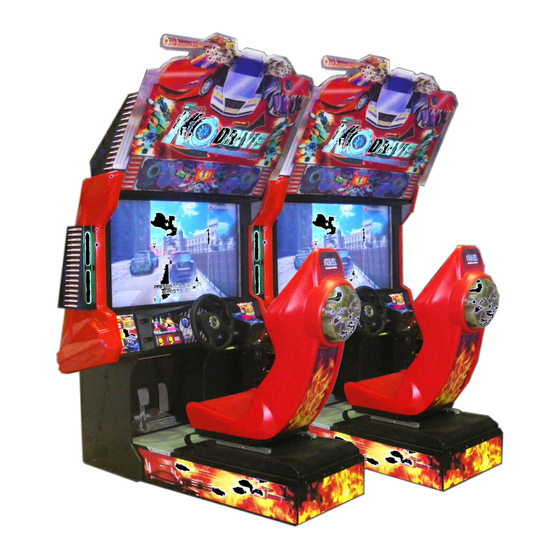
Page 34: Game Description
GAME DESCRIPTION This title is a car racing game, mainly featured with multiplayer competition . It supports up to 6 cabinets to play at the same time. Ignite the engine and launch a high speed racing competition with attack and being attacked iterations. The last place racer still has the opportunity to overturn the ranking and win the race. - Page 35 Select the course. Turn the wheel to select the course, press Start/Weapon button to confirm the selection. Scenes in total, and each scene contains 4 courses. STAGE LAPS IN DEFAULT UNLOCK CONDITION IN DEFAULT CANADA 1 Unlocked in the beginning CANADA 2 Unlocked in the beginning CANADA 3...
- Page 36 GAME FEATURES In weapon upgrade screen, the player is allowed to use the KO props obtained in the game to upgrade the weapon. The player is also allowed to insert coins and press the brake pedal to purchase KO props in weapon upgrade screen.
- Page 37 8-2 GAMEPLAY SCREEN RACE SCREEN Position Time and Lap indicator Mini Map Weapon Window Speed Gauge K.O Counter WEAPON SYSTEM The player will obtain corresponding color represented weapon by random when their car passes through the weapon panel on the course attack Machine gun, tracking missile, etc yellow...
- Page 38 When the race is over, a summary screen will be displayed (score screen). The player will enter weapon upgrade screen to upgrade the weapon by KO props. The player will then enter continue screen, insert the required coins and press Start/Weapon button to go back to weapon upgrade screen to continue the game.
-
Page 39: Explanation Of Test And Data Display
EXPLANATION OF TEST AND DATA DISPLAY Perform tests and data checks periodically by manipulating the TEST Button and SERVICE Button in the cabinet. Follow the instructions in this chapter to conduct checks when the game machine is first installed, when money is being collected, or when the game machine does not operate properly. -
Page 40: Switch Unit And Coin Meter
9-1 SWITCH UNIT AND COIN METER. Never touch places other than those specified. Touching places not specified can cause electric shock and short circuit accidents. • Adjust the sound to the optimum volume, taking into consideration the environmental requirements of the installation location. • Removing the Coin Meter circuitry renders the game inoperable. 9-1-1 SWITCH UNIT Open the coin chute door, and the switch unit shown will appear. -
Page 41: System Test Mode
9-2 SYSTEM TEST MODE The details of changes to Test Mode settings are saved when you exit from each Test Mode by selecting EXIT. Be careful because if the power is turned off before that point, changes to the settings will be lost. SYSTEM TEST MODE can be used to check the information or the operation of RINGWIDE, adjust Monitor color, and perform coin/credit settings. -
Page 42: Game Test Mode
9-3 GAME TEST MODE ● To change settings in the GAME TEST MODE, simply making changes on the setting screen will not be effective. Complete the TEST MODE in normal fashion. ● Use with the specified settings. If settings other than those specified are used, inappropriate operations or malfunction may occur. - Page 43 9-3-2 BOOKKEEPING Each game record can be viewed BOOKKEEPING 1/12 COIN CHUTE #1 COIN CHUTE #2 TOTAL COINS COIN CREDITS SERVICE CREDITS TOTAL CREDITS PRESS TEST BUTTON TO CONTINUE BOOKKEEPING SCREEN 1/12 COIN CHUTE #1 Number of coins inserted in coin chute 1. COIN CHUTE #2 Number of coins inserted in coin chute 2.
- Page 44 Bookkeeping – Page 2 – Data on Average Game Times BOOKKEEPING 2/12 NUMBER OF GAMES SINGLE PLAY FIRST PLAY CONTINUE PLAY MULTIPLAY FIRST PLAY CONTINUE PLAY BUT K.O COUNTS NUMBER OF BONUS GAMES TOTAL TIME *D **H **M PLAY TIME *D **H **M AVERAGE PLAY TIME **M **S...
- Page 45 Bookkeeping – Page 3 – Data on Car selections BOOKKEEPING 3/12 NUMBER OF CARS FORTRESS THUNDER HORNET * PARADISE ROYAL GHOST EVOLUTION ITASYA VIPER WILDKING FLAMINGO FREEDOM PRESS TEST BUTTON TO CONTINUE BOOKKEEPING 3/12 NUMBER OF CARS Counts for all the selection of cars in the game. FORTRESS Counts for selection of FORTRESS in the game.
- Page 46 Bookkeeping – Page 4 – Data on Course selections BOOKKEEPING 4/12 NUMBER OF COURSES CANADA 1 CANADA 2 CANADA 3 CANADA 4 EGYPT 1 EGYPT 2 EGYPT 3 EGYPT 4 LASVEGAS 1 LASVEGAS 2 LASVEGAS 3 LASVEGAS 4 SHANGHAI 1 SHANGHAI 2 SHANGHAI 3 SHANGHAI 4...
- Page 47 Bookkeeping – Page 5 – Data on first placements BOOKKEEPING 5/12 NUMBER OF FIRSTS CANADA 1 CANADA 2 CANADA 3 CANADA 4 EGYPT 1 EGYPT 2 EGYPT 3 EGYPT 4 LASVEGAS 1 LASVEGAS 2 LASVEGAS 3 LASVEGAS 4 SHANGHAI 1 SHANGHAI 2 SHANGHAI 3 SHANGHAI 4...
- Page 48 Bookkeeping – Page 6 – Data on second placements BOOKKEEPING 6/12 NUMBER OF SECONDS CANADA 1 CANADA 2 CANADA 3 CANADA 4 EGYPT 1 EGYPT 2 EGYPT 3 EGYPT 4 LASVEGAS 1 LASVEGAS 2 LASVEGAS 3 LASVEGAS 4 SHANGHAI 1 SHANGHAI 2 SHANGHAI 3 SHANGHAI 4...
- Page 49 Bookkeeping – Page 7 – Data on third placements BOOKKEEPING 7/12 NUMBER OF THIRD CANADA 1 CANADA 2 CANADA 3 CANADA 4 EGYPT 1 EGYPT 2 EGYPT 3 EGYPT 4 LASVEGAS 1 LASVEGAS 2 LASVEGAS 3 LASVEGAS 4 SHANGHAI 1 SHANGHAI 2 SHANGHAI 3 SHANGHAI 4...
- Page 50 Bookkeeping – Page 8 – Data on fourth placements BOOKKEEPING 8/12 NUMBER OF FOURTH CANADA 1 CANADA 2 CANADA 3 CANADA 4 EGYPT 1 EGYPT 2 EGYPT 3 EGYPT 4 LASVEGAS 1 LASVEGAS 2 LASVEGAS 3 LASVEGAS 4 SHANGHAI 1 SHANGHAI 2 SHANGHAI 3 SHANGHAI 4...
- Page 51 Bookkeeping – Page 9 – Data on fifth placements BOOKKEEPING 9/12 NUMBER OF FIFTH CANADA 1 CANADA 2 CANADA 3 CANADA 4 EGYPT 1 EGYPT 2 EGYPT 3 EGYPT 4 LASVEGAS 1 LASVEGAS 2 LASVEGAS 3 LASVEGAS 4 SHANGHAI 1 SHANGHAI 2 SHANGHAI 3 SHANGHAI 4...
- Page 52 Bookkeeping – Page 10 – Data on sixth placements BOOKKEEPING 10/12 NUMBER OF SIXTH CANADA 1 CANADA 2 CANADA 3 CANADA 4 EGYPT 1 EGYPT 2 EGYPT 3 EGYPT 4 LASVEGAS 1 LASVEGAS 2 LASVEGAS 3 LASVEGAS 4 SHANGHAI 1 SHANGHAI 2 SHANGHAI 3 SHANGHAI 4...
- Page 53 Bookkeeping – Page 11 – Data on seventh placements BOOKKEEPING 11/12 NUMBER OF SEVENTH CANADA 1 CANADA 2 CANADA 3 CANADA 4 EGYPT 1 EGYPT 2 EGYPT 3 EGYPT 4 LASVEGAS 1 LASVEGAS 2 LASVEGAS 3 LASVEGAS 4 SHANGHAI 1 SHANGHAI 2 SHANGHAI 3 SHANGHAI 4...
- Page 54 Bookkeeping – Page 12 – Data on eighth placements BOOKKEEPING 12/12 NUMBER OF EIGHTH CANADA 1 CANADA 2 CANADA 3 CANADA 4 EGYPT 1 EGYPT 2 EGYPT 3 EGYPT 4 LASVEGAS 1 LASVEGAS 2 LASVEGAS 3 LASVEGAS 4 SHANGHAI 1 SHANGHAI 2 SHANGHAI 3 SHANGHAI 4...
- Page 55 9-3-3 INPUT TEST Select INPUT TEST to display the following screen and check the status of input devices. This test should be used periodically to check that each input device is functioning correctly. INPUT TEST PLAYER STEERING BRAKE START/WEAPON TEST SERVICE SELECT WITH SERVICE AND PRESS TEST BUTTON...
- Page 56 9-3-4 OUTPUT TEST This screen is for confirming the proper operation of each output device used by the game. Periodically use this screen to check the status of each output device. OUTPUT TEST BILLBOARD LAMP LEFT SIDE LAMP RIGHT SIDE LAMP START/WEAPON LAMP EXIT SELECT WITH SERVICE...
- Page 57 9-3-5 GAME ASSIGNMENTS Adjust all game settings. GAME ASSIGNMENTS ADVERTISE SOUND GAME DIFFICULTY NORMAL MAX RANK TO UNLOCK COURSE LAP ASSIGNMENT EXIT SELECT WITH SERVICE AND PRESS TEST BUTTON GAME ASSIGNMENTS screen ■ Controls - Press the SERVICE Button to select menu item. - Press the TEST Button to change the value of the selected item.
- Page 58 GAME ASSIGNMENTS LAPS:CANADA 1 LAPS: CANADA 2 LAPS: CANADA 3 LAPS: CANADA 4 LAPS: EGYPT 1 LAPS: EGYPT 2 LAPS: EGYPT 3 LAPS: EGYPT 4 LAPS: LASVEGAS 1 LAPS: LASVEGAS 2 LAPS: LASVEGAS 3 LAPS: LASVEGAS 4 LAPS: SHANGHAI 1 LAPS: SHANGHAI 2 LAPS: SHANGHAI 3 LAPS: SHANGHAI 4...
- Page 59 9-3-6 TIME SETTING Set game time for all aspects. TIME SETTING COURSE SELECT CAR SELECT POWER UP EXIT SELECT WITH SERVICE AND PRESS TEST BUTTON TIME ADJUSTMENT screen ■ Controls - Press the SERVICE Button to select menu item. - Press the TEST Button to change the value of the selected item. - Select EXIT and press the TEST Button to return to the GAME TEST MENU screen.
- Page 60 9-3-7 BONUS SETTING Bonus related setting. BONUS SETTING 1ST PLACE FREE RACE SINGLE PLAY MULTI PLAY EXIT SELECT WITH SERVICE BUTTON AND PRESS TEST BUTTON BONUS SETTING screen ■ Controls - Press the SERVICE Button or START Button to select menu item. - Select EXIT (WITH SAVE) and press the TEST Button to save the values you have set and return to the GAME TEST MENU screen.
- Page 61 9-3-8 LINK SETTING When 2 or machines are connected, these options are available to select. LINK SETTINGS LINK ID TOTAL MACHINE GROUP SELECT WITH SERVICE BUTTON AND PRESS TEST BUTTON LINK SETTING screen ■ Controls • Press Service Button to select menu item. •...
- Page 62 9-3-9 FORCE FEEDBACK This screen is for setting the strength of the steering wheel’s force feedback. FORCE FEEDBACK Initialize Kickback... Please DO NOT touch steering wheel When the system initialization is complete, the FORCE FEEDBACK Screen will appear. FORCE FEEDBACK NO JVS NODE PRESS TEST AND SERVICE BUTTON TO EXIT...
- Page 63 9-3-10 INPUT ADJUSTMENTS This screen is for setting the input device utilized in game. INPUT ADJUSTMENTS STEERING ADJUSTMENT GAS ADJUSTMENT BRAKE ADJUSTMENT DEFAULT SETTING EXIT SELECT WITH SERVICE BUTTON AND PRESS TEST TO NEXT INPUT ADJUSTMENT SCREEN ■ Controls • Press Service Button to select menu item. •...
- Page 64 STEERING ADJUSTMENTS (MIN -40: MAX 40) STEERING - *** CENTRE LEFT RIGHT EXIT PRESS TEST AND SERVICE BUTTON TO EXIT STEERING ADJUSTMENT Screen ■ Menu Items (MIN -40:MAX 40) Min and Max values STEERING = *** Display the output value of current steering setting Displays current position/value of steering CENTRE LEFT...
- Page 65 GAS ADJUSTMENTS Gas standard setting in game. GAS ADJUSTMENTS NO JVS NODE PRESS TEST AND SERVICE BUTTON TO EXIT NO JVS NODE Connected Screen GAS ADJUSTMENTS PEDAL UP XXH CALIBRATING PEDAL DOWN EXIT SELECT WITH SERVICE BUTTON AND PRESS TEST BUTTON GAS ADJUSTMENT Screen ■...
- Page 66 BRAKE ADJUSTMENTS Brake standard setting in game. BRAKE ADJUSTMENTS NO JVS NODE PRESS TEST AND SERVICE BUTTON TO EXIT NO JVS NODE Connected Screen BRAKE ADJUSTMENTS BRAKE PEDAL UP XXH CALIBRATING PEDAL DOWN EXIT SELECT WITH SERVICE BUTTON AND PRESS TEST BUTTON BRAKE ADJUSTMENT Screen ■...
- Page 67 DEFAULT SETTING Reset all the adjustment value to default value. DEFAULT SETTINGS YES (RESET) (CANCEL) SELECT WITH SERVICE BUTTON AND PRESS TEST BUTTON DEFAULT SETTING 1/2 Screen DEFAULT SETTINGS COMPLETE PRESS TEST BUTTON TO EXIT DEFAULT SETTING 2/2 Screen ■ Control Press Service Button to select menu item.
- Page 68 9-3-11 BACKUP DATA CLEAR Clear all game records BACKUP DATA CLEAR (RESET) (CANCEL) SELECT WITH SERVICE BUTTON AND PRESS TEST TO NEXT BACKUP DATA CLEAR creen 1/2 BACKUP DATA CLEAR COMPLETE SELECT WITH SERVICE BUTTON AND PRESS TEST TO NEXT BACKUP DATA CLEAR creen 2/2 ■...
-
Page 69: System Information
9-4 SYSTEM INFORMATION The SYSTEM INFORMATION screen displays system information. The following information is displayed on this screen. SYSTEM INFORMATION 1/2 The SYSTEM INFORMATION 1/2 screen displays system information. ■ SYSTEM INFORMATION 1/2 Screen SYSTEM INFORMATION 1/2 KEYCHIP KEYCHIP ID A72*-*********** MODEL TYPE REGION MOTHER BOARD MAIN ID ****-***********... - Page 70 SYSTEM INFORMATION 2/2 The SYSTEM INFORMATION 2/2 screen displays system information. Press the TEST Button on the SYSTEM INFORMATION 2/2 screen to return to the SYSTEM TEST MODE screen. ■ SYSTEM INFORMATION 2/2 Screen SYSTEM INFORMATION 2/2 VOLTAGE CPU CORE +*.**[V] VOLTAGE 3.3V +*.**[V] VOLTAGE 5V +**.**[V] VOLTAGE 12V...
-
Page 71: Storage Information
9-5 STORAGE INFORMATION The STORAGE INFORMATION screen displays information on the game stored in the program installer device. This screen is also used when uninstalling the game stored within the program installer device. Until preparations to launch the game are complete, a now checking screen will be displayed and uninstall cannot be performed. -
Page 72: Jvs Test
If no JVS I/O boards are connected, the message “NO JVS NODE” will be displayed. ■ JVS TEST Screen JVS TEST INPUT TEST NODE -> EXIT NAME SEGA ENTERPRISES,LTD.: I/O BD JVS :837-13551: Ver1.00 CMD VER JVS VER COM VER SWITCH... - Page 73 The following information is displayed on this screen. The currently displayed JVS I/O board number and the total number of connected NODE JVS I/O boards NAME Name of the connected I/O board, etc. CMD VER Command format version JVS VER JVS standard version COM VER Communication version...
- Page 74 JVS INPUT TEST Use the JVS INPUT TEST to test the JVS input. The hexadecimal input information from the JVS I/O board will be displayed in real time. ■ JVS INPUT TEST Screen JVS TEST INPUT TEST NODE SYSTEM ROTARY 0000 PLAYER 0000 ROTARY 0000 PLAYER 0000...
-
Page 75: Monitor Test
9-7 MONITOR TEST Use MONITOR TEST to check the output of the monitor. Enter MONITOR TEST and the MONITOR TEST 1/2 Screen will be displayed. ■ MONITOR TEST Screen 1/2 MONITOR TEST 1/2 PRESS TEST BUTTON TO NEXT Press TEST Button and the screen will change to the MONITOR TEST 2/2 Screen. ■ MONITOR TEST Screen 2/2 MONITOR TEST 2/2 PRESS TEST BUTTON TO EXIT... -
Page 76: Speaker Test
9-8 SPEAKER TEST Use SPEAKER TEST to check the output of each speaker by having them each emit a test sound. Select each speaker with the cursor and press the TEST Button to turn that speaker ON or OFF. When set to ON a test sound will be emitted from that speaker. It is possible to set multiple speakers to emit the test sound at the same time. -
Page 77: Coin Assignments
9-9 COIN ASSIGNMENTS Use COIN ASSIGNMENTS to alter the credit settings. The game will award players the number of credits determined here. Settings will only be saved if they have been changed. ■ COIN ASSIGNMENTS Screen COIN ASSIGNMENTS COIN CHUTE TYPE COMMON ••••••••••••••••••••• (A) SERVICE TYPE COMMON •••••••••••••••••••••... - Page 78 (C-1) COIN CHUTE #1 COIN TO CREDIT RATE (Coin and credit conversion rate 1) 1 COIN(S) COUNT AS 1 CREDIT(S) 1 coin counts as 1 credit 2 COIN(S) COUNT AS 1 CREDIT(S) 2 coins count as 1 credit 3 COIN(S) COUNT AS 1 CREDIT(S) 3 coins count as 1 credit 4 COIN(S) COUNT AS 1 CREDIT(S) 4 coins count as 1 credit...
- Page 79 The following information is displayed on this screen. (E-1) COIN CHUTE #1 MULTIPLIER Coin conversion rate for #1. (How many coins 1 inserted coin counts for) (E-2) COIN CHUTE #2 MULTIPLIER Coin conversion rate for #2. (How many coins 1 inserted coin counts for) NOTE: When (A) COIN CHUTE TYPE is set to “COMMON,”...
- Page 80 (H) GAME COST SETTING Use the COIN ASSIGNMENTS GAME COST SETTING screen to set the cost (number of required credits) that the game program will use to determine if there are enough credits to play the game. A total of 8 game costs can be defined. The game cost is defined by the BOOT ID, and when the second boot recognizes the game, the game cost defined by the BOOT ID will be displayed.
-
Page 81: Clock Settings
9-10 CLOCK SETTINGS Use CLOCK SETTING to set the date and time. Use the SERVICE Button to move the cursor to the category that you wish to change and press the TEST Button to increase that value. Holding the TEST Button down will make the value continuously increase. ■... - Page 82 CLOCK SETTING CLOCK 20**/ */ *(TUE) 12:00:00 TIMEZONE UTC+09:00 DAYLIGHT SAVING TIME(DST) •••••••••••••••••••••• ENABLE DST START MAR/2nd/SUN 02:00:00 DST END NOV/1st/SUN 02:00:00 -> EXIT SELECT WITH SERVICE BUTTON AND PRESS TEST BUTTON [DAYLIGHT SAVING TIME (DST): ENABLE] (C) DAYLIGHT SAVING TIME (DST) Displays the daylight saving time setting.
-
Page 83: Network Test
9-11 NETWORK TEST Use NETWORK SETTING to determine network settings or to test the network. There is no need to alter these settings for a game that does not use a network. ■ NETWORK SETTING (Setting Menu) Screen NETWORK SETTING MAIN NETWORK NETWORK TEST -> EXIT SELECT WITH SERVICE BUTTON AND PRESS TEST BUTTON The following information is displayed on this screen. - Page 84 MAIN NETWORK Select MAIN NETWORK on the NETWORK SETTING (Setting Menu) and the following screen will be displayed. ■ NETWORK SETTING (Network Setting) Screen NETWORK SETTING MAC ADDRESS **-**-**-**-**-** ••••••••••••••••••• A DHCP ******** •••••••••••••••••••••••• B IP ADDRESS ••••••••••••••••••••••••••••••••••• C ***.***.***.*** SUBNET MASK ••••••••••••••••••••••••••••••••• D ***.***.***.*** GATEWAY ••••••••••••••••••••••••••••••••••••...
-
Page 85: Exit
NETWORK TEST Check the network connection. The test will begin as soon as this screen is displayed. The machine cannot be operated until the test is finished. ■ NETWORK TEST Screen NETWORK TEST DHCP ------------ **** LOOPBACK -------- **** LINKUP ---------- **** GATEWAY --------- **** ROUTER ---------- **** HOPS SERVER ---------- ****... -
Page 86: Controller Unit(S)
10 CONTROLLER UNIT(S) • When working with the product, be sure to turn the power off. Working with the power on may cause an electric shock or short circuit. • Be careful not to damage the wires. Damaged wires may cause an electric shock, short circuit or present a risk of fire. -
Page 87: Removing The Control Panel
Be sure to perform volume's move value setting in the INPUT ASSIGNMENTS in the Game Test Mode after replacing or adjusting the Volume. In cases the Steering operability is poor and the adjustment of VOLUME SETTING in the TEST mode has no effect, the causes may be the volume gear's mesh failure and or volume malfunctioning. -
Page 88: Adjusting/Replacing The Volume
10-2 ADJUSTING/REPLACING THE VOLUME ADJUSTMENT PROCEDURE Loosen the 2 screws that secure the VR Bracket and move the VR Bracket to adjust the angle and condition of the gear alignment. Keeping the handle straight, align the gears so that the direction of the D Cut side of the V.R. Shaft matches that shown in the diagram. - Page 89 REPLACEMENT PROCEDURE This procedure requires the following tools: Phillips screwdriver for the M4 screws, 1.5 mm hexagonal wrench, 11- 12 mm monkey wrench, nipper, cutter, wire stripper, soldering iron, industrial dryer and heat-shrinkable tube. Remove the connectors. Remove the 2 screws securing the VR Bracket and remove the entire Bracket and V.R. Loosen the 2 hexagon socket screws on the Gear Holder and remove the Gear Holder.
-
Page 90: Greasing
10-3 GREASING • Be sure to use the designated grease. Using undesignated grease can cause parts damage. • Do not apply grease to locations other than as specified. Doing so may create a risk of operational problems and deterioration of parts. •... -
Page 91: Start Button Assy
10-4 START BUTTON ASSY ● When working with the product, be sure to turn the power off. Working with the power on may cause an electric shock or short circuit. ● Be careful not to damage the wires. Damaged wires may cause an electric shock, short circuit or present a risk of fire. - Page 92 Strart Button/switch replacement Follow the instructions below to change the microswitch. Unscrew and remove the START BUTTON PLATE as explained on the previous page. Remove the microswitch by unclipping it from the Lamp Housing Remove the wiring harness from the old microswitch and re-attach it to the replacement switch in the same manner Clip the Microswich back into the lamp house making sure that it is fully in place.
-
Page 93: Brake And Accelerator Unit
10-5 BRAKE AND ACCELERATOR UNIT When working with the product, be sure to turn the power off. Working with the power on may cause an electric shock or short circuit. However, the unit must be switched on when using test mode. Do not touch any part of the unit except those areas indicated. - Page 94 When the accelerator pedal is not being pressed, the accelerator volume should have a value of 30H or less. When the pedal is being pressed, the value should be C0H or greater. When the brake pedal is not being pressed, the value should be 35H or less. When the pedal is being pressed, it should be D0H or more.
- Page 95 Replacing the Volume Switch off the unit. Remove the two screws and lift off the potentio cover . TRUSS SCREW (2), chrome M4x8 POTENTIO COVER POTENTIOBASE 10-3-1 FIG. 0 1 Detach the connector from the volume to be replaced. Remove the single screw that secures the potentiobase. (see 10-31 FIG. 02). Without detaching the volume, remove the potentiobase.
- Page 96 Greasing Use only the specified grease. Using any other kind of grease can result in damage to parts. Once every three months, you should apply grease to the gear contacts and spring parts. Use Grease Mate-brand spray grease (Part No.: 090-0066). POTENTIOBASE 10-3-2 FIG.
-
Page 97: Graphics Display
GRAPHICS DISPLAY 11-1 SAFETY PRECAUTIONS WHEN HANDLING THE MONITOR Responding to breakdown or abnormality ● If smoke or a strange odor appears, immediately unplug the power cable from the power source. Continuing to use the product may cause a fire or an electric shock. Ensure that smoke is no longer emitted, and contact the point of purchase. - Page 98 11-2 CLEANING THE SCREEN SURFACE ● Use a soft, dry cloth (flannel-type) to wipe away dirt. Do not use materials such as coarse mesh gauze. ● Alcohol (ethanol) is the recommended solvent for removing dirt. When using a cleaning agent, follow the precautions below. Dilute neutral cleaning agents for home use with water.
- Page 99 11-3 ADJUSTMENT METHOD All adjustment values are set accurately at the time of shipping from the factory. Do not readjust these values needlessly or apply adjustments not specified in this manual. The display may not appear properly if the values are incorrect.
- Page 100 Button Names and Functions 11-3 Fig. 02 MENU: Turn the Picture Menu display ON and OFF. SELECT: Gains entry to the Item selected in the menu. (Highlights in Yellow when selected) Exits the Item adustment. Any changes made during this operation are actioned. DOWN: Moves the cursor (Black Bar) down to select a menu item.
- Page 101 On-Screen Display (OSD) Press the MENU Button while the OSD is not displayed to bring up the Picture Menu. On the Picture Menu, it is possible to perform various screen adjustments. 11-3 Fig. 03 Use the UP and DOWN Buttons to move the ‘Black Bar’to the item you want to adjust. After selecting the desired item, pressing the SELECT Button will extend the MENU Screen and allow adjustments to be changed.
- Page 102 On-Screen Display (OSD) <continued> 11-3 Fig. 05 Available Settings (Selects Operation Mode)) Selection availble - 6500K - 9300K - USER BRIGHTNESS (Adjust Brightness) Adjust screen Brightness. - Values: 0 - 100 (0” being the darkest setting, and “100” being the brightest) CONTRAST (Adjust Contrast) Adjust Contrast level.
-
Page 103: Coin Handling
COIN HANDLING Handling the Coin Jam If the coin is not rejected when the REJECT button is pressed, open the coin chute door and open the selector gate. After removing the jammed coin, put a normal coin in and check to see that the selector correctly functions. 12-1 CLEANING THE COIN SELECTOR ●... - Page 104 CLEANING THE COIN SELECTOR <continued> Remove and clean smears by using a soft cloth dipped in water or diluted chemical detergent and then squeezed dry. Remove the CRADLE.. When removing the retaining ring (E ring) be very careful so as not to bend the rotary shaft. Remove stain from the rotary shaft and shaft CRADLE receiving portions by wiping off with a soft cloth.
-
Page 105: Adjusting The Price Of Play
12-2 ADJUSTING THE PRICE OF PLAY This product comes equipped with a Money Controls SR3 Coin Acceptor. To adjust the price of play ALL credit setting are adjusted via the EXCEL CREDIT BOARD. IMPORTANT! The CREDIT SETTINGS within the SYSTEM TEST MODE must be set to 1 coin 1 credit to allow the CREDIT BOARD to function correctly. - Page 106 REGIONAL AND ACCEPTOR SETTINGS (SW3)
- Page 107 STERLING PRICE OF PLAY SETTINGS (SW1)
- Page 108 EURO PRICE OF PLAY SETTINGS (SW1)
-
Page 109: Lamps And Lighting
LAMPS AND LIGHTING • When working with the product, be sure to turn the power off. Working with the power on may cause an electric shock or short circuit. • You may get burned by hot lamps. Pay full attention to the lamps when performing the work. -
Page 110: Led Lighting - Billboard
13-2 LED LIGHTING - BILLBOARD THIS WORK ON TOP OF THE CABINET, SHOULD NOT BE UNDERTAKEN WITHOUT THE USE OF A SUITABLE STEP OR FOOTSTOOL. MAKE SURE THAT THE MAIN SUPPLY VOLTAGE TO THE MACHINE IS SWITCHED OFF BEFORE ATTEMPTING TO CARRY OUT THIS WORK The Billboard lighting is located inside the back section of the Billboard Base, before attempting to change the LED, TURN THE POWER OFF. - Page 111 The LED STRIP is self adhesive. Before removal, unclip the connector at the R/H edge. Carefully peel off the LED STRIP from the back of the BILLBOARD. LED STRIP Remove Connector Replace the LED strip with a new one of the same type and re-assemble the Billboard in the reverse order.
-
Page 112: Feature Led Lower
13-3 FEATURE LED LOWER THIS WORK ON TOP OF THE CABINET, SHOULD NOT BE UNDERTAKEN WITHOUT THE USE OF A SUITABLE STEP OR FOOTSTOOL. MAKE SURE THAT THE MAIN SUPPLY VOLTAGE TO THE MACHINE IS SWITCHED OFF BEFORE ATTEMPTING TO CARRY OUT THIS WORK The K.O Feature Lamp is a strip of bright white LED’s mounted on a self adhesive strip. - Page 113 Adhere the LED strip back into location. TEST the LED strip in OUTPUT test before refitting the BILLBOARD Plate. Refit the BILLBOARD plate following the instructions of the previous section in reverse order.
-
Page 114: Feature Led Sides
13-4 FEATURE LED SIDES THIS WORK ON TOP OF THE CABINET, SHOULD NOT BE UNDERTAKEN WITHOUT THE USE OF A SUITABLE STEP OR FOOTSTOOL. MAKE SURE THAT THE MAIN SUPPLY VOLTAGE TO THE MACHINE IS SWITCHED OFF BEFORE ATTEMPTING TO CARRY OUT THIS WORK The K.O Feature Lamps are strips of bright white LED’s mounted on a self adhesive strip. - Page 115 Carefully peel off the adhesive LED strip. Apply the new LED adhesive strip in the same way following the instructions in revers order.
-
Page 116: Periodic Inspection
PERIODIC INSPECTION The items listed below require periodic check and maintenance to retain the performance of this machine and to ensure safe business operation. When handling the controller, the player will be in direct contact with it. In order to always allow the player to enjoy the game, be sure to clean it regularly. - Page 117 Move the Seat to the rear most position and apply spray greasing to the portion shown at the right once every 3 months using NOK KLUBER L60 or GREASE MATE SEGA PART No. 090-0066. After greasing, move the Seat a few times forward and backward so as to allow the grease to be applied all over uniformly.
-
Page 118: Troubleshooting
TROUBLESHOOTING 15-1 TROUBLESHOOTING (WHEN NO ERROR MESSAGE IS SHOWN) • In order to prevent electric shock and short circuit, be sure to turn power off before performing work. • Be careful so as not to damage wirings. Damaged wiring can cause electric shock or short circuit. •... - Page 119 Sound is not emitted. Sound volume adjustment is not Adjust the Switch Unit’s sound correct adjustment volume. Faulty connections for various Check the connections for the game connectors board, amp, speakers and Volume connectors Malfunctioning BD, amp and speaker Perform Sound Test. Sounds are emitted and Faulty connections for the visual Check the connections for the monitor...
- Page 120 Steering (Servomotor) A g e i n g o f t h e f o r c e f e e d b a c k Reset in the Test Mode. i s w e a k i n i t s f o r c e mechanism feedback Does not accept input in...
- Page 121 Replacing Fuses • In case fuse replacements other than those stated in this manual are necessary, contact where you purchased the product from for inquiries regarding this matter. • In order to prevent an electric shock, be sure to turn power off and unplug from the socket outlet before performing work by touching the internal parts of the product.
-
Page 122: Game Board
GAME BOARD ● When working with the product, be sure to turn the power off. Working with the power on may cause an electric shock or short circuit. ● Be careful not to damage the wires. Damaged wires may cause an electric shock, short circuit or present a risk of fire. - Page 123 16-1 GAME BD - LOCATION ● When returning the game board after making repairs or replacements, make sure that there are no errors in the connection of connectors. Erroneous connections can lead to electrical shock, short circuits or fires. ● When connecting a connector, check the direction carefully. Connectors must be connected in only one direction.
- Page 124 Undo and remove the (6) M6x20 HEX BLT BLK from around the seat base and the (4) M5x12 Torx T25 Security Screws M6x20 Hex Blt Blk M5x12 Torx T25 Security Screw Once all fixings have been removed, lift the front edge of the Assy Seat slightly to clear the Foot Plate Tab. Once clear, carefully slide the Assy Seat back and rest in a safe position back on the Base Box.
- Page 125 TILT the footplate in an upwards direction until the LIP on the backside of the footplate is clear of the front section of floor and REMOVE the plate. Tilt Foot Plate With the Foot Plate removed the Assy Game Bd is now accessible. Unscrew the (2) M4x25 PH PAN MSCR screws from the front edges of the wooden base to which the GAME BD is secured .
- Page 126 Once all harnessing has been disconnected, carefully lift the ASSY GAME BD out of the cabinet. ASSY GAME BD Do not open the Game Board without the express permission of SEGA. If for any reason entry has been gained into the Game Board without the permission of SEGA, then all warranty rights become void.
-
Page 127: Communication Play
COMMUNICATION PLAY For this game, up to 8 machines can be networked together allowing up to 8 players to play simultaneously. In this instance, connecting the communication cable and adjustment to the settings for communication play will be required. 17-1 INSTALLATION PRECAUTIONS •... - Page 128 Distance between Machines The maximum distance between the game machines depends on the length of the cables connecting them, but make sure the units are separated from each other by at least 49 cm (19.2 in) so that players can pass between them. 17-1 Fig 01...
-
Page 129: Connecting The Communication Cable
Cable as this will cause a network failure or possible damage to networking components. When linking 4 or more seats a Hub Kit must be used. Please contact SEGA or your local distributors office for further technical or sales information... -
Page 130: Network Play Settings
17-3 NETWORK PLAY SETTINGS Each of the linked machines must be set up for network play. If the machines are not set up correctly, network play will not be possible. For this game, up to 4 machines can be connected to allow up to 4 players to play simultaneously. Turn on the power on each machine to be used in network play. -
Page 131: Network Play Precautions
17-4 NETWORK PLAY PRECAUTIONS • In network play, difficulty level and other settings are made from CABINET ID Number 1. Changing the settings at CABINET ID Number 1 also changes the settings for other units. • Only use the network cable supplied to network 2 machines. When connecting 3 or more cabinets a Network Hub MUST be used along with standard Lan Network Cables). -
Page 132: Design Related Parts
DESIGN RELATED PARTS For the warning display stickers, refer to Section 1. PD-0002UK PD-2020UK PD-1356UK PD-2015UK PD-1503UK PD-1504UK PD-2201K PD-1505UK... -
Page 133: Parts List
PARTS LIST TOP ASSY KO DRIVE STD US PD-00005UK TOP ASSY KO DRIVE STD US RD-0300X-01UK RD-0320UK ASSY COIN CHUTE TOWER STD US ASSY SW UNIT PD-1000XUK PD-1200UK PD-1250XUK ASSY COCKPIT US ASSY MONITOR CABI ASSY SUB MONITOR 42” CABI PD-1290UK ASSY 42”... - Page 134 1 ASSY TOP KO DRIVE STD US (PD-00005UK) (D-1/2)
- Page 135 1 ASSY TOP KO DRIVE STD US (PD-00005UK) (D-2/2) ITEM NO PART NUMBER DESCRIPTION PD-0300X-01UK ASSY COIN CHUTE TOWER STD US PD-1000XUK ASSY COCKPIT US RD-0004UK PLATE CCT BLANK 421-7988-91UK STICKER SERIAL NUMBER UK PD-1355UK BRKT SPKR PNL LWR PD-1356UK...
- Page 136 2 ASSY COIN CHUTE TOWER STD US (RD-0300X-01UK) (D-1/1) ITEM NO PART NUMBER DESCRIPTION RD-0301XUK COIN CHUTE TOWER RD-0320UK ASSY SW UNIT RD-0305UK SPACER CCT STD RD-0306UK PLATE BLANK CCT STD **101 220-5732-01 DFMD SAU HAPP H40-7000-00 **102 OS1247 ALUMINIUM STICKY CLIP ASK-3 **201 000-P00410-W M4X10 MSCR PAN W/FS PAS...
- Page 137 3 ASSY SW UNIT (RD-0320XUK) (D-1/1) ITEM NO PART NUMBER DESCRIPTION ***1 RD-0321-01UK SW BRKT US ***101 838-14548-01UK SW & VOL CTL BD ***102 280-L00706-PM STANDOFF 6.4MM HOLE PM ***103 EP1380-01 CREDIT BOARD EXCEL ***104 220-5643UK COIN METER SMALL 12V ***105 OS1247 ALUMINIUM STICKY CLIP ASK-3...
- Page 138 4 ASSY COCKPIT US (PD-1000XUK) (D-1/1) 7 14 ITEM NO PART NUMBER DESCRIPTION PD-1200UK ASSY MONITOR CABI PD-1500XUK ASSY MAIN BASE US RD-1001UK MON CABI PLATE UPPER RD-1004UK STRUT CABINET SUPPORT RD-1005UK BRKT OUTER CABI SUPP **12 PD-1502UK BASE LID F **14 RD-1011UK PLATE CONN BASE BOX...
- Page 139 5 ASSY MONITOR CABI (PD-1200UK) (D-1/3) Inside...
- Page 140 5 ASSY MONITOR CABI (PD-1200UK) (D-2/3) ITEM NO PART NUMBER DESCRIPTION ***1 PD-1250XUK ASSY SUB MONITOR 42" CABI ***3 PD-1290UK ASSY 42" LCD MONITOR ***4 130-5284 SPEAKER 8OHM F01612HO NJS ***5 PD-1300XUK ASSY MONITOR MASK ***7 PD-2000UK ASSY CONTROL PANEL ***10 RD-1203UK SIDE PANEL HOLDER...
- Page 141 5 ASSY MONITOR CABI (PD-1200UK) (D-3/3) ***301 PD-60004UK WH DC 12V OUT ***302 PD-60008UK WH ENCODER & MOTOR A ***303 PD-60009UK WH SPKR A ***304 PD-60010UK WH I/O ***305 PD-60011UK WH AC DISTRIBUTION EXTN ***306 PD-60012UK WH 5V I/O EXTN ***307 PD-60013UK WH COMS B...
- Page 142 6 ASSY SUB MONITOR CABI (PD-1250XUK) (D-1/1) ITEM NO PART NUMBER DESCRIPTION ****1 PD-1251UK MONITOR CABINET *****2 RD-1021UK WOODEN LOWER DOOR *****3 RD-1003UK UPPER DOOR ****4 PD-1257UK BRKT 42 MONITOR UPPER SUPPORT ****5 PD-1255UK MONITOR SUPPORT ****6 RD-1256UK MONITOR SUPPORT PLATE ****201 030-000630-SB M6X30 BLT W/S BLK...
- Page 143 7 ASSY LCD MONITOR (PD-1290UK) (D-1/1) ITEM NO PART NUMBER DESCRIPTION ****1 PD-1281UK LCD BRKT ****2 GST-1110UK PANEL PRISMA BD MOUNT ****101 200-6042-01-AUO DISPLAY 42" LCD T420HW09-V2 ****102 400-242-024-01 PSU 42" LCD PVP-2420 ****103 280-L00640-WX STANDOFF 6MM WOOD XL ****104 280-A00748-PM ROUTER TWIST D7 SO4.8 PANEL M ****107...
- Page 144 8 ASSY MONITOR MASK (PD-1300XUK) (D-1/1) ITEM NO PART NUMBER DESCRIPTION ****1 PD-1301UK MASK MONITOR ****2 PD-1304UK BRKT MASK UPPER ****3 PD-1305UK BRKT MASK LOWER ****4 PD-1308XUK GLASS 42 LCD PROTECTIVE ****101 OS1230 FOAM STRIP 2MM X 10MM ****201 000-P00410-W M4X10 MSCR PAN W/FS PAS...
- Page 145 9 ASSY CONTROL PANEL (PD-2000UK) (D-1/2) 3 201 203 213...
- Page 146 9 ASSY CONTROL PANEL (PD-2000UK) (D-2/2) ITEM NO PART NUMBER DESCRIPTION ****1 PD-2202UK PLATE LOGO ****2 610-0875 ASSY HANDLE MECHA ****3 SPG-2001X-N STEERING WHEEL ****4 SPG-2002 STEERING EMBLEM ****9 PD-2007UK PANEL HANDLE MECHA ****10 PD-2001UK CTRL PANEL COVER ****11 DYN-1209X HANDLE COLLAR ****13 INY-1204...
- Page 147 10 ASSY SIDE POD L (PD-1220UK) (D-1/1) ITEM NO PART NUMBER DESCRIPTION ***1 PD-1215UK POD SIDE L ***2 PD-1217UK PERSPEX SIDE POD ***3 PD-1221UK STICKER SIDE PANEL L ***201 050-F00400 M4 NUT FLG SER PAS ***202 068-441616 M4 WSHR 16OD FLT PAS 11 ASSY SIDE POD R (PD-1225UK) (D-1/1) ITEM NO...
- Page 148 12 ASSY MAIN BASE (PD-1500XUK) (D-1/2) ITEM NO PART NUMBER DESCRIPTION ***1 PD-1520UK ASSY BASE BOX ***2 PD-1540UK AC UNIT ***3 PD-1600UK ASSY ADJUSTABLE SEAT ***4 610-0874-01 ASSY ACCEL & BRAKE ***5 PD-4500XUK ASSY MAIN BD US ***7 PD-1538UK BASE LID R ***8 RAL-2007X RUBBER HOLDER R TWIN...
- Page 149 12 ASSY MAIN BASE (PD-1500XUK) (D-2/2) ***201 000-P00408-WB M4X8 MSCR PAN W/FS BLK ***202 032-000425 M4X25 W/BLT PAS ***203 068-441616 M4 WSHR 16OD FLT PAS ***204 030-000620-SB M6X20 BLT W/S BLK ***205 060-F00600-SB M6 WSHR FORM A FLT BLK ***206 030-000825-SB M8X25 BLT W/S BLK ***207...
- Page 150 13 ASSY BASE BOX (PD-1520UK) (D-1/1) ITEM NO PAT NUMBER DESCRIPTION ****1 PD-1531UK MAIN BASE BLANK ****102 MA1007 CASTOR SWIVEL 63mm NYLON ****103 601-5699UK-01 LEG ADJ M16X100 1L/NUT ****104 253-5460-01 AIR VENT BLACK ****204 030-000816 M8X16 BLT PAS ****205 060-S00800 M8 WSHR SPR PAS ****206 000-T00416-0B...
- Page 151 14 ASSY AC UNIT (PD-1540UK) (D-1/1) 104 201 ITEM NO PAT NUMBER DESCRIPTION ****1 PD-1541UK AC BRKT ****2 TFF-0402UK CONN COVER ****3 LB1096 STICKER PROTECTIVE EARTH ****101 EP1302 EUROSOCKET FUSED 10A 250VAC ****102 514-5078-5000 FUSE 5X20 CERAMIC SB 5000mA ****103 SW1109 SWITCH ROCKER 250V AC ****104...
- Page 152 15 ASSY ADJUSTABLE SEAT (PD-1600UK) (D-1/1) ITEM NO PAT NUMBER DESCRIPTION ****1 PD-1601-A SEAT ****2 PD-1601UK SEAT BASE ****3 RD-1602UK SEAT TRAY ****6 RD-1605UK PROTECT RUBBER ****10 PD-1676UK BRKT REAR FORMING ****12 RD-1611UK TRAY COVER FRONT ****13 RD-1612UK TRAY COVER REAR ****15 PD-1614UK PLATE SLIDER...
- Page 153 16 ASSY MAIN BD (PD-4500XUK) (D-1/1) ITEM NO PART NUMBER DESCRIPTION ****1 PD-4501UK WOODEN BASE MAIN BD ****2 847-0001D-02 ASSY CASE WDE W 1GB EXP ****3 253-5644-040BG KEY CHIP RGW PD1 ****4 610-0816-0049 DVD SOFT KIT PD1 E/S ****5 LB1111 STICKER PLEASE RECYCLE ****6 CFB-4003-01UK...
- Page 154 17 ASSY 12VDC FAN (GST-1340UK) (D-1/1) ITEM NO PART NUMBER DESCRIPTION ****1 105-5340-01 FAN BRKT LONG ****101 260-0012-01UK FAN DC 12V RoHs ****102 FN1012 FAN GUARD METAL 120MM (FG-12) ****201 000-P00312-W M3X12 MSCR PAN W/FS PAS...
-
Page 155: Colour Code
COLOUR CODE The DC power wire color for this product is different from previous SEGA titles. Working from the previous wire colors will create a high risk of fire. The color codes for the wires used in the diagrams in the following chapter are as follows. -
Page 156: Schematic Diagrams
SCHEMATIC DIAGRAMS (D-1/2)... - Page 157 (D-2/2)...
-
Page 158: Service And Support
SERVICE AND SUPPORT - SEGA TOTAL SOLUTIONS - 42 Barwell Business Park Leatherhead Road, Chessington, Surrey, KT9 2NY United Kingdom Tel: +44 (0) 208 391 8060 Fax: +44 (0) 208 391 8096 xclusive uppliers of pares To Heathrow Airport...
Need help?
Do you have a question about the KO DRIVE and is the answer not in the manual?
Questions and answers