Table of Contents
Advertisement
Quick Links
Masibus Automation & Instrumentation Pvt. Ltd.
B/30, GIDC Electronics Estate,
Sector-25, Gandhinagar-382044, Gujarat, India
+91 79 23287275-77
Email: support@masibus.com
D
u
a
l
C
D
u
a
l
C
Web: www.masibus.com
User's Manual
O
N
-
O
O
N
-
O
h
a
n
n
e
l
T
e
m
p
e
r
a
h
a
n
n
e
l
T
e
m
p
e
r
a
+91 79 23287281
F
F
C
O
N
T
R
O
L
L
E
R
F
F
C
O
N
T
R
O
L
L
E
R
L
C
5
2
9
6
D
C
L
C
5
2
9
6
D
C
t
u
r
e
C
o
n
t
r
o
l
l
e
r
t
u
r
e
C
o
n
t
r
o
l
l
e
r
Advertisement
Table of Contents

Related Manuals for Masibus LC5296 DC


Summary of Contents for Masibus LC5296 DC
- Page 1 User’s Manual Masibus Automation & Instrumentation Pvt. Ltd. B/30, GIDC Electronics Estate, Sector-25, Gandhinagar-382044, Gujarat, India +91 79 23287275-77 +91 79 23287281 Email: support@masibus.com Web: www.masibus.com...
-
Page 2: Table Of Contents
Model: LC5296 Dual Channel Temperature Controller Doc. Ref. no.:- m61C/om/101 Issue no. 01D/ENGG-114 Contents 1. INTRODUCTION ....................4 Foreword ......................4 Notice ........................4 Trademarks ......................4 Product Ordering Code ..................4 List of Accessories ....................5 Safety Precautions ....................5 2. - Page 3 Model: LC5296 Dual Channel Temperature Controller Doc. Ref. no.:- m61C/om/101 Issue no. 01D/ENGG-114 Procedure for RET-zero and RET-span ............ 24 9. COMMUNICATION PROTOCOL–MODBUS RTU ..........25 Introduction ....................25 Parameter Address Details ................ 25 Exceptional Response ................26 10. APPENDIX ......................27 10.1 Troubleshooting ..................
-
Page 4: Introduction
Every effort has been made to ensure accuracy in the preparation of this manual. Should any errors or omissions come to your attention, however, please inform MASIBUS Sales office or sales representative. Under no circumstances may the contents of this manual, in part or in whole, be transcribed or copied without our permission. -
Page 5: List Of Accessories
Model: LC5296 Dual Channel Temperature Controller Doc. Ref. no.:- m61C/om/101 Issue no. 01D/ENGG-114 Ordering Code Options Model Input-1* Input-2 Power Supply Relay o/p Output-1 Output-2 85-265VAC / LC5296-DC Pt-100 Pt-100 None None None 100-300VDC 4-20mA 4-20mA 18-36 VDC 4-20 mA 4-20 mA 0-20mA 0-20mA... -
Page 6: Specifications
Model: LC5296 Dual Channel Temperature Controller Doc. Ref. no.:- m61C/om/101 Issue no. 01D/ENGG-114 2. SPECIFICATIONS 2.1 Inputs Analog Input Input-1 Type RTD (Pt100), Current, Voltage Input-2 Type RTD (Pt100), Current, Voltage Display Range Refer Table-2.1 Accuracy + (0.25% of Full Span + 1 degree) RTD input. + (0.1% of Full Span + 1 count) for Linear input. -
Page 7: Communication Details
Model: LC5296 Dual Channel Temperature Controller Doc. Ref. no.:- m61C/om/101 Issue no. 01D/ENGG-114 Relay Output Relays Type Single Change over Three Terminals (C, NO, NC) Rating 2A @ 230VAC / 30VDC Retransmission Output Number of output 1 / 2 Retransmission mapping With respect to Input no. -
Page 8: Environmental Conditions
Model: LC5296 Dual Channel Temperature Controller Doc. Ref. no.:- m61C/om/101 Issue no. 01D/ENGG-114 2.6 Environmental Conditions TEMPCO For Input-1 to PV1 Display < 100ppm. For Input-2 to PV2 Display < 100ppm. Humidity 30% to 95% RH (Non-Condensing) Instrument Warm-up Time Approx. -
Page 9: Physical Specifications & Mounting Details
Model: LC5296 Dual Channel Temperature Controller Doc. Ref. no.:- m61C/om/101 Issue no. 01D/ENGG-114 3. PHYSICAL SPECIFICATIONS & MOUNTING DETAILS Front Bezel 96 x 96 mm Panel Cutout 92mm(+0.8) x 92mm(+0.8) Depth Behind The Panel 65 mm with Terminal Weight 300g Approx. Enclosure Material Enclosure Protection IP20... -
Page 10: Terminal Connections
Model: LC5296 Dual Channel Temperature Controller Doc. Ref. no.:- m61C/om/101 Issue no. 01D/ENGG-114 4. TERMINAL CONNECTIONS Fig 4.1: Terminal Connection Detail of LC5296-DC Terminal No. Description 2 (NC1) For Relay-1 potential free Contacts (Use 230V -2A load) 3 (NO1) ... -
Page 11: How To Connect Wires
Model: LC5296 Dual Channel Temperature Controller Doc. Ref. no.:- m61C/om/101 Issue no. 01D/ENGG-114 Fig 4.5: Lead Termination Detail How to connect wires? Before carrying out wiring, turn off the power to the controller and check that the cables to be connected are not alive because there is a possibility of electric shock. NOTE: ... - Page 12 Model: LC5296 Dual Channel Temperature Controller Doc. Ref. no.:- m61C/om/101 Issue no. 01D/ENGG-114 Fig 4.4: RS485 Connection Details User’s Manual Page 12 of 30...
-
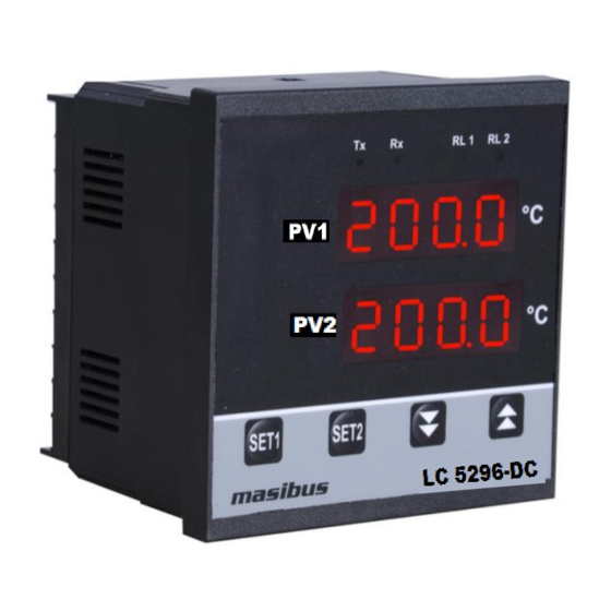
Page 13: Front Panel Details
Model: LC5296 Dual Channel Temperature Controller Doc. Ref. no.:- m61C/om/101 Issue no. 01D/ENGG-114 5. FRONT PANEL DETAILS Front Panel Description Name of Symbol Function LC5296-DC Part Increment the Value of any Increment Parameter. Decrement the Value of any Decrement Parameter. - Page 14 Model: LC5296 Dual Channel Temperature Controller Doc. Ref. no.:- m61C/om/101 Issue no. 01D/ENGG-114 4 digital 0.56 inch RED Display Display parameter name when user set parameter. Display Parameter Value when in (Present Value) Edit mode. (For Single Display Display Model Only) ...
-
Page 15: Menu Layout
Model: LC5296 Dual Channel Temperature Controller Doc. Ref. no.:- m61C/om/101 Issue no. 01D/ENGG-114 6. MENU LAYOUT User’s Manual Page 15 of 30... -
Page 16: Run Time Indication/Function
Model: LC5296 Dual Channel Temperature Controller Doc. Ref. no.:- m61C/om/101 Issue no. 01D/ENGG-114 Run Time Indication/Function Following parameters can view or change during run time. In upper display, it shows Process value for input-1. In lower display, it shows Process value for input-2. Set Point Setting Parameter Se tt in g n a m e a n d... - Page 17 Model: LC5296 Dual Channel Temperature Controller Doc. Ref. no.:- m61C/om/101 Issue no. 01D/ENGG-114 Set PV Input -2 Type rtd.1 / rtd/ 0-5v / 1-5v Value Input Type Range RTD.1 -199.9 to 850.0 °C -200 to 850 °C IN 2 Input-2 Type 0-5 V (1n 2) 0-5 V /...
- Page 18 Model: LC5296 Dual Channel Temperature Controller Doc. Ref. no.:- m61C/om/101 Issue no. 01D/ENGG-114 0 : 0 0.0 : 1 0.00 : 2 0.000 : 3 Set position of Decimal Point on Display for PV2. 0 / 0.0 / 0.00 / 0.000 DP 2 Decimal Point- Input Type is...
- Page 19 Model: LC5296 Dual Channel Temperature Controller Doc. Ref. no.:- m61C/om/101 Issue no. 01D/ENGG-114 Retransmission-1 Output Type This output is according to PV input. Zero & Span acts as Min & Max value of retransmission o/p scale respectively. 0-5v / 1-5v / 0-10 / 4-20 / 0-20 RT-1 Retransmission 0 : 0-5V...
-
Page 20: Map Mode
Model: LC5296 Dual Channel Temperature Controller Doc. Ref. no.:- m61C/om/101 Issue no. 01D/ENGG-114 Hysteresis Value (in °C) for Relay-2 during ON-OFF type Control. 1 to 100 RTD Input 0.1 to 10.0 RTD.1 Input Hysteresis – 2 HY-2 1 to 100 Linear Input with DP=0 (Hy-2) (For Relay-2) -
Page 21: Calibration Mode
Model: LC5296 Dual Channel Temperature Controller Doc. Ref. no.:- m61C/om/101 Issue no. 01D/ENGG-114 Calibration Mode C ALI BR ATION P AR AM ETERS Parameter Default (PV displ ay) Setting Name & Description Show if Only Value Symbol Name CZ-1 Calibration Zero for PV Input-1 Calibration Zero-1 (CZ-1) (PV Display : Current PV) - Page 22 Model: LC5296 Dual Channel Temperature Controller Doc. Ref. no.:- m61C/om/101 Issue no. 01D/ENGG-114 Examples: How to change Input Type? User’s Manual Page 22 of 30...
-
Page 23: Control Function
Model: LC5296 Dual Channel Temperature Controller Doc. Ref. no.:- m61C/om/101 Issue no. 01D/ENGG-114 7. CONTROL FUNCTION ON/OFF Control ON/OFF Controller is the simplest form of temperature control device. The output from the device is either on or off, with no middle state. An on-off controller will switch the output only when the temperature crosses the set point. -
Page 24: Calibration Procedure
Model: LC5296 Dual Channel Temperature Controller Doc. Ref. no.:- m61C/om/101 Issue no. 01D/ENGG-114 8. CALIBRATION PROCEDURE Procedure for CAL-zero and CAL-span The instrument is factory calibrated for the specified range, but due to long term drift of components, re-calibration may be necessary in some cases. For calibrating the instrument a reliable source is required. -
Page 25: Communication Protocol-Modbus Rtu
Model: LC5296 Dual Channel Temperature Controller Doc. Ref. no.:- m61C/om/101 Issue no. 01D/ENGG-114 9. COMMUNICATION PROTOCOL–MODBUS RTU Introduction The unit can be connected in RS-485 communication data link either in multi drop or repeat mode. Each unit must have unique Serial Number. Entire range of addresses (1 to 247) may be used. -
Page 26: Exceptional Response
Model: LC5296 Dual Channel Temperature Controller Doc. Ref. no.:- m61C/om/101 Issue no. 01D/ENGG-114 Baud Rate 40011 R + W Relay Delay -1 40012 R + W Relay Delay -2 40013 R + W Retransmission o/p Type -1 40014 R + W Retransmission o/p Type -2 40015 Hysteresis 1... -
Page 27: Appendix
Model: LC5296 Dual Channel Temperature Controller Doc. Ref. no.:- m61C/om/101 Issue no. 01D/ENGG-114 10. APPENDIX 10.1 Troubleshooting If the operating display does not appear after turning on the controller’s power, follow the measures in the procedure below. If a problem appears complicated, contact our sales representative. IMPORTANT Take note of the parameter settings when asking the vendor for repair. -
Page 28: Retramission Output Table For Open /Over /Under Condition
Model: LC5296 Dual Channel Temperature Controller Doc. Ref. no.:- m61C/om/101 Issue no. 01D/ENGG-114 Relay type Relay Hi-On PV > SP PV < SP Open sensor Up scale Down scale Low-On PV > SP PV < SP Open sensor Up scale Down scale 10.3 Retramission Output Table for Open /Over /Under Condition... -
Page 29: Jumper Settings For Add-On Card Selection & Retransmission
Model: LC5296 Dual Channel Temperature Controller Doc. Ref. no.:- m61C/om/101 Issue no. 01D/ENGG-114 10.5 Jumper Settings for Add-on Card Selection & Retransmission Output Type These units come with different Variants differing by various Output option available. There are Two Addon Card Slots available on PCB of Signal Card. Among them One Slot is fixed for Retransmission (Analog) Output. -
Page 30: Load Connection
Model: LC5296 Dual Channel Temperature Controller Doc. Ref. no.:- m61C/om/101 Issue no. 01D/ENGG-114 Jumper Setting for Retransmission card: m61Cao201 Jumper Setting for Retransmission card: m61Cao102 10.6 Load connection Electrical precautions during use Electrical noise generated by switching of inductive loads can create momentary disruption, erratic display, latch up, data loss or permanent damage to the instrument.
Need help?
Do you have a question about the LC5296 DC and is the answer not in the manual?
Questions and answers