Table of Contents
Advertisement
Quick Links
Model: LC5296-XP-AT / LC5296-XP/LC5296-XP-I
Doc. Ref. no. :- m61D/om/101
Issue no. 17
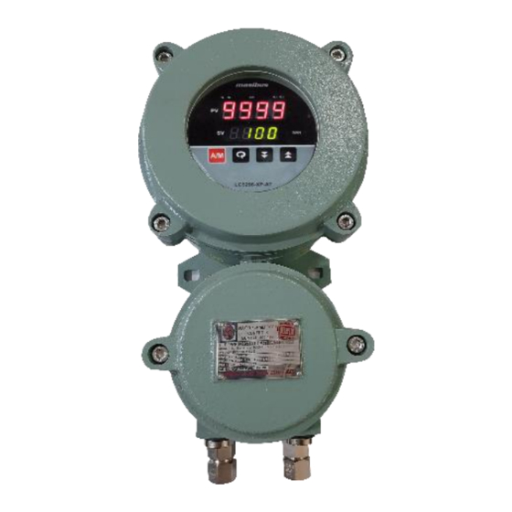
FLAMEPROOF CONTROLLER
Masibus Automation & Instrumentation Pvt. Ltd.
Sector-25, Gandhinagar-382044, Gujarat, India
+91 79 23287275-77
User's Manual
B/30, GIDC Electronics Estate,
Email: support@masibus.com
Web: www.masibus.com
User's Manual
LC5296-XP
LC5296-XP-I
LC5296-XP-AT
+91 79 23287281
Page 1 of 56
Advertisement
Table of Contents

Related Manuals for Masibus LC5296-XP


Summary of Contents for Masibus LC5296-XP
- Page 1 Model: LC5296-XP-AT / LC5296-XP/LC5296-XP-I Doc. Ref. no. :- m61D/om/101 Issue no. 17 User’s Manual FLAMEPROOF CONTROLLER LC5296-XP LC5296-XP-I LC5296-XP-AT Masibus Automation & Instrumentation Pvt. Ltd. B/30, GIDC Electronics Estate, Sector-25, Gandhinagar-382044, Gujarat, India +91 79 23287275-77 +91 79 23287281 Email: support@masibus.com Web: www.masibus.com...
-
Page 2: Table Of Contents
4.1 How to connect wires ..................17 5. FRONT PANEL DETAILS .................. 18 5.1 Front Panel Description ................. 18 6. MENU LAYOUT for LC5296-XP-AT ..............21 RUN Time Indication/Function ..............22 *SET POINT SETTING ................23 6.3 AUTO TUNE MODE ..................23 6.4 CONFIGURATION MODE................ - Page 3 Model: LC5296-XP-AT / LC5296-XP/LC5296-XP-I Doc. Ref. no. :- m61D/om/101 Issue no. 17 7. MENU LAYOUT for LC5296-XP................. 32 7.1 RUN Time Indication/Function............... 34 7.2 Set Point Setting .................... 34 7.3 CONFIGURATION MODE................34 7.4 CALIBRATION MODE ................... 38 8. CONTROL FUNCTION ..................40 8.1 ON/OFF Control .....................
-
Page 4: Introduction
Every effort has been made to ensure accuracy in the preparation of this manual. Should any errors or omissions come to your attention, however, please inform MASIBUS Sales office or sales representative. Under no circumstances may the contents of this manual, in part or in whole, be transcribed or copied without our permission. - Page 5 DESCRIPTION OF SIGNS LC5296-XP-AT can be configured as PID or ON-OFF Controller. To change configuration of LC5296-XP-AT, following steps are required to follow. From menu parameter settings if user enter 5296 Password in Pass menu in configuration menu then it will displays...
-
Page 6: Specifications
Model: LC5296-XP-AT LC5296-XP/LC5296-XP-I Doc. Ref. no.:- m61D/om/101 Issue no. 17 2. SPECIFICATIONS 2.1 Inputs Analog Input Input Type Thermocouple, RTD (Pt100), Current, Voltage Display Range Refer Table-2.1 Accuracy + (0.25% of FS+ 1 degree) for T/C and RTD input. + (0.1% of FS+ 1 count) for Linear input. -
Page 7: Display & Keys
Model: LC5296-XP-AT / LC5296-XP/LC5296-XP-I Doc. Ref. no. :- m61D/om/101 Issue no. 17 2.2 Display & Keys Model Display Specification 4-Digit, 7-Segment, Red, Character height of PV Display 0.56” 4-Digit, 7-Segment, Green, Character height SV / Parameter Display of 0.40” LC5296-XP-AT... - Page 8 2 (For LC5296-XP) Optional For LC5296-XP-I Type Single Change over Three Terminals (C, NO, NC) Rating 2A @ 230VAC / 30VDC Pulse Output (SSR)(For LC5296-XP-AT Only) Output signal Voltage Pulse Output Output signal On-condition 11VDC or more Off-condition 2VDC or less...
-
Page 9: Communication Details
Approx. 15 minutes Ambient temperature 0 to 55°C Storage Temperature 0 to 80°C 2.7 Special Feature 1. Input Scalability for Linear Input type(only for LC5296-XP and LC5296-XP-I model) 2. Ramp Soak Function (only for LC5296-XP-AT) Page 9 of 56 User’s Manual... -
Page 10: Physical Specifications & Mounting Details
Model: LC5296-XP-AT LC5296-XP/LC5296-XP-I Doc. Ref. no.:- m61D/om/101 Issue no. 17 3. PHYSICAL SPECIFICATIONS & MOUNTING DETAILS 3.1 External Dimensions Unit: mm Mounting method: Wall Mounting Weight:For IIA,IIB& IIC Enclosure:Approx. 3 Kg. For IIA & IIB Enclosure: Approx. 2.6 Kg. Type of Protections:... - Page 11 Model: LC5296-XP-AT / LC5296-XP/LC5296-XP-I Doc. Ref. no. :- m61D/om/101 Issue no. 17 INTERNAL VIEW WITH TERMINAL CONNECTION DETAILS BOTTOM VIEW FOR CABLE ENTRY Page 11 of 56 User’s Manual...
- Page 12 Model: LC5296-XP-AT LC5296-XP/LC5296-XP-I Doc. Ref. no.:- m61D/om/101 Issue no. 17 TOP VIEW FOR DISPLAY CARD ASSEMBLY 2. Mechanical Details for IIA, IIB & IIC Enclosure FRONT VIEW OF DEVICE Page 12 of 56 User’s Manual...
- Page 13 Model: LC5296-XP-AT / LC5296-XP/LC5296-XP-I Doc. Ref. no. :- m61D/om/101 Issue no. 17 INTERNAL VIEW WITH TERMINAL CONNECTION DETAILS BOTTOM VIEW FOR CABLE ENTRY Page 13 of 56 User’s Manual...
-
Page 14: External Dimensions For Dual Compartment Enclosure
Model: LC5296-XP-AT LC5296-XP/LC5296-XP-I Doc. Ref. no.:- m61D/om/101 Issue no. 17 TOP VIEW FOR DISPLAY CARD ASSEMBLY 3.2 External Dimensions for dual compartment enclosure Unit: mm Mounting method: Wall Mounting Weight: Approx. 6Kg. Type of Protections: Flameproof (Explosion Proof) EX-d Area Classification: Hazardous Location of Zone 1 &... - Page 15 Model: LC5296-XP-AT / LC5296-XP/LC5296-XP-I Doc. Ref. no. :- m61D/om/101 Issue no. 17 FLP Dual compartment Enclosure Front View and Section view Page 15 of 56 User’s Manual...
-
Page 16: Terminal Connections
Model: LC5296-XP-AT LC5296-XP/LC5296-XP-I Doc. Ref. no.:- m61D/om/101 Issue no. 17 4. TERMINAL CONNECTIONS 4.1 Single compartment enclosure 4.2 Dual compartment enclosure Terminal No. Description For Relay-2 potential free Contacts (Use 230V -2A load) 1 (C2) Alarm-2 o/p. 2 (NO2) -
Page 17: How To Connect Wires
Model: LC5296-XP-AT / LC5296-XP/LC5296-XP-I Doc. Ref. no. :- m61D/om/101 Issue no. 17 4.1 How to connect wires Before carrying out wiring, turn off the power to the controller and check that the cables to be connected are not alive because there is a possibility of electric shock. -
Page 18: Front Panel Details
Shows ambient value for T/C Input in RUN Increment mode. In Manual Mode this key is used to Increment the %Power. (for LC5296-XP-AT Only) Enter into Edit Mode. Decrement Decrement the Value of any Parameter in ... - Page 19 Model: LC5296-XP-AT / LC5296-XP/LC5296-XP-I Doc. Ref. no. :- m61D/om/101 Issue no. 17 Shows %Power value if Device is in Auto Mode during RUN mode. (for LC5296-XP- AT Only) In Manual Mode this key is used to Decrement the %Power. (for LC5296-XP-AT Only) ...
- Page 20 Model: LC5296-XP-AT LC5296-XP/LC5296-XP-I Doc. Ref. no.:- m61D/om/101 Issue no. 17 Indication (RS-485). ON when device is receiving some Data Indication (RS-485). NOTE: : Available for this Model. : Not Available for this Model. Page 20 of 56...
-
Page 21: Menu Layout For Lc5296-Xp-At
Model: LC5296-XP-AT / LC5296-XP/LC5296-XP-I Doc. Ref. no. :- m61D/om/101 Issue no. 17 6. MENU LAYOUT for LC5296-XP-AT Long Press to Return to RUN Mode from anywhere in the Menu. Page 21 of 56 User’s Manual... -
Page 22: Run Time Indication/Function
Model: LC5296-XP-AT LC5296-XP/LC5296-XP-I Doc. Ref. no.:- m61D/om/101 Issue no. 17 MENU LAYOUT for LC5296-XP-AT 6.1 RUN Time Indication/Function Following parameters can view or change during run time. Press Decrement key to show percentage power Auto Mode (0.0 to100.0%) For Thermocouple input type, Press Increment key to show ambient temperature. -
Page 23: Set Point Setting
Model: LC5296-XP-AT / LC5296-XP/LC5296-XP-I Doc. Ref. no. :- m61D/om/101 Issue no. 17 During manual mode, Increment key and Shift Decrement Key will use to modify the percentage power. Press to toggle between AUTO & MANUAL mode or display time. -
Page 24: Configuration Mode
Model: LC5296-XP-AT LC5296-XP/LC5296-XP-I Doc. Ref. no.:- m61D/om/101 Issue no. 17 1 : DIR (Direct) Adjust Manual Reset Value It is used to shift P Band for critical Controlling situations. (Applicable only if Control O/P is “P”) -(PB/2) to +(PB/2) Manual EX. - Page 25 Model: LC5296-XP-AT / LC5296-XP/LC5296-XP-I Doc. Ref. no. :- m61D/om/101 Issue no. 17 Input Type Range Value TC E -200 to 1000 °C TC J -200 to 1200 °C TC K -200 to 1372 °C TC T -100 to 400 °C...
- Page 26 Model: LC5296-XP-AT LC5296-XP/LC5296-XP-I Doc. Ref. no.:- m61D/om/101 Issue no. 17 1 to 99 sec Hysteresis Value (in °C) for Relay-1 during ON-OFF type Control. 1 to 100 TC & RTD Input Hysteresis – 1 HY-1 Control Type is 0.1 to 100.0 RTD.1 Input...
- Page 27 Model: LC5296-XP-AT / LC5296-XP/LC5296-XP-I Doc. Ref. no. :- m61D/om/101 Issue no. 17 Set Direction for the Retransmission Output-1 rev / dir 0 : REV (REVERSE) 1 : DIR (DIRECT) EX. If i/p is RTD.1, ZERO=0, SPAN=600, Device Supports RTR.1=4-20mA &...
- Page 28 Model: LC5296-XP-AT LC5296-XP/LC5296-XP-I Doc. Ref. no.:- m61D/om/101 Issue no. 17 Control Output High Limit in %. CO.HI Control Output Control output 0.0 to 100.0 % (Co.Hi) High Limit in % type is PID (It will be always greater then CO.LO) PV.A...
-
Page 29: Calibration Mode
Model: LC5296-XP-AT / LC5296-XP/LC5296-XP-I Doc. Ref. no. :- m61D/om/101 Issue no. 17 Select Auto Cold Junction Compensation Auto Cold required or not for TC input Type. A.CJC no / yes Junction Input Type is TC (a.CJC) Compensation 0 : NO... -
Page 30: Setparamode
Model: LC5296-XP-AT LC5296-XP/LC5296-XP-I Doc. Ref. no.:- m61D/om/101 Issue no. 17 Device Calibration Span for Supports RTS2 Retransmission-2 Retransmission Output-2 Dual (rts2) SPAN (SV Display : If voltage: 8.000 Retransmission If Current: 20.00) Output 6.6 *SETPARAMODE *only shows if SP.PW is Yes in configuration mode... - Page 31 Model: LC5296-XP-AT / LC5296-XP/LC5296-XP-I Doc. Ref. no. :- m61D/om/101 Issue no. 17 Page 31 of 56 User’s Manual...
-
Page 32: Menu Layout For Lc5296-Xp
Model: LC5296-XP-AT LC5296-XP/LC5296-XP-I Doc. Ref. no.:- m61D/om/101 Issue no. 17 7. MENU LAYOUT for LC5296-XP Page 32 of 56 User’s Manual... - Page 33 Model: LC5296-XP-AT / LC5296-XP/LC5296-XP-I Doc. Ref. no. :- m61D/om/101 Issue no. 17 MENU LAYOUT for LC5296-XP Page 33 of 56 User’s Manual...
-
Page 34: Run Time Indication/Function
Model: LC5296-XP-AT LC5296-XP/LC5296-XP-I Doc. Ref. no.:- m61D/om/101 Issue no. 17 7.1 RUN Time Indication/Function Following parameters can view or change during run time. For Thermocouple input type, Press Increment key to show ambient temperature 7.2 Set Point Setting Pressing SET key PV Display shows C1.sp (C1.SP) message. SV display shows ControlSet Point-1 Value. - Page 35 Model: LC5296-XP-AT / LC5296-XP/LC5296-XP-I Doc. Ref. no. :- m61D/om/101 Issue no. 17 current input Automatically change to the Input Lower Range with changing of Input Type -200 ZERO (Refer Above Table) Zero (zero) (If TC K) Can be set to any value within the Input Range &...
- Page 36 Model: LC5296-XP-AT LC5296-XP/LC5296-XP-I Doc. Ref. no.:- m61D/om/101 Issue no. 17 Set Control O/P & Retransmission state when Input OPEN condition. OPES OPEN Sensor down / up (opes) Status 0 : DOWN 1 : UP Relay Delay is amount of time (in sec), that...
- Page 37 Model: LC5296-XP-AT / LC5296-XP/LC5296-XP-I Doc. Ref. no. :- m61D/om/101 Issue no. 17 Device supports Unit ID for Modbus-RS485 Communication SR.NO Serial No. RS485 (sr.no) 1 to 247 Communicatio Set Modbus RS485 Communication Baud Rate Device supports 9600 / 19.2k / 38.4k...
-
Page 38: Calibration Mode
Model: LC5296-XP-AT LC5296-XP/LC5296-XP-I Doc. Ref. no.:- m61D/om/101 Issue no. 17 Retransmission-2 Output Type This output is according to PV input. Zero & Span acts as Min & Max value of retransmission o/p scale respectively. 0-5v / 1-5v / 0-10v / 4-20 / 0-20 Device RTR.2... - Page 39 Model: LC5296-XP-AT / LC5296-XP/LC5296-XP-I Doc. Ref. no. :- m61D/om/101 Issue no. 17 Calibration Zero for Device Retransmission Output-1 RT.1.Z Retransmission-1 Supports (rt.1.z) ZERO Retransmission (SV Display : If voltage: 0.000 Output If Current: 4.000) Calibration Span for Device Retransmission Output-1 RT.1.S...
-
Page 40: Control Function
Model: LC5296-XP-AT LC5296-XP/LC5296-XP-I Doc. Ref. no.:- m61D/om/101 Issue no. 17 8. CONTROL FUNCTION Model LC5296-XP-AT is a microcontroller based PID controller& ON-OFF Controller. Model LC5296-XPismicrocontroller based ON-OFF Controller without PID controlling. 8.1 ON/OFF Control ON/OFF Controller is the simplest form of temperature control device. The output from the device is either on or off, with no middle state. -
Page 41: Pid Control
For LC5296-XP-AT, ON-OFF control type is available for Relay & SSR output type only. In LC5296-XP-AT, when PB,TI,TD term is ‘0’ and auto tune is set ‘no’, and unit is not in manual mode, then control output will work as on-off controller else it will work as PID controller 8.2 PID Control... - Page 42 Model: LC5296-XP-AT LC5296-XP/LC5296-XP-I Doc. Ref. no.:- m61D/om/101 Issue no. 17 Control Parameter:- Proportional BAND: Proportional action is the action which the control output varies in proportion to the deviation between the setting value and the processing temperature. If the proportional band is narrowed, even if the output changes by a slight variation of the processing temperature, better control results can be obtained as the offset decreases.
- Page 43 Model: LC5296-XP-AT / LC5296-XP/LC5296-XP-I Doc. Ref. no. :- m61D/om/101 Issue no. 17 BASIC PID TUNING PROCEDURE: ADJUSTMENT SYMPTOM SOLUTION SEQUENCE Slow Response Decrease PB Proportional Band Overshoot or Oscillation Increase PB Slow Response Decrease TI Integral Time Instability orOscillation Increase TI...
-
Page 44: Ramp And Soak Function
Model: LC5296-XP-AT LC5296-XP/LC5296-XP-I Doc. Ref. no.:- m61D/om/101 Issue no. 17 8.3 Ramp and Soak Function: (LC5296-XP-AT Only) This function is used to stop the sudden change of set point. The ramp function is performed in following conditions. The target set point is changed. Target set point number is changed. -
Page 45: Alarm Output
Model: LC5296-XP-AT / LC5296-XP/LC5296-XP-I Doc. Ref. no. :- m61D/om/101 Issue no. 17 9. ALARM OUTPUT Available Only for LC5296-XP-AT For all Alarm outputs there are five settings. (As shown in configuration mode Menu) Set Value (in run mode) Type ... - Page 46 Model: LC5296-XP-AT LC5296-XP/LC5296-XP-I Doc. Ref. no.:- m61D/om/101 Issue no. 17 NOTE:- LIT = LED on, UNLIT = LED off Up arrow indicate Alarm will ON from this value. Down arrow indicate Alarm will OFF from this value. Page 46 of 56...
- Page 47 Model: LC5296-XP-AT / LC5296-XP/LC5296-XP-I Doc. Ref. no. :- m61D/om/101 Issue no. 17 Hysteresis (Dead band): Hysteresis (Dead band) application is shown in the figure. Direction: All the figures here are shown considering the setting is direct (Normal). If the settings are reversing (Fail Safe), the relays will behave exactly the opposite.
-
Page 48: Calibration Procedure
Model: LC5296-XP-AT LC5296-XP/LC5296-XP-I Doc. Ref. no.:- m61D/om/101 Issue no. 17 10. CALIBRATION PROCEDURE 10.1 Procedure for CAL-zero and CAL-span The instrument is factory calibrated for the specified range, but due to long term drift of components, re-calibration may be necessary in some cases. For calibrating the instrument a reliable source is required. -
Page 49: Communication Protocol-Modbus Rtu
Model: LC5296-XP-AT / LC5296-XP/LC5296-XP-I Doc. Ref. no. :- m61D/om/101 Issue no. 17 11. COMMUNICATION PROTOCOL–MODBUS RTU 11.1 INTRODUCTION The unit can be connected in RS-485 communication data link either in multi drop or repeat mode. Each unit must have unique Serial Number. Entire range of addresses (1 to 247) may be used. - Page 50 Model: LC5296-XP-AT LC5296-XP/LC5296-XP-I Doc. Ref. no.:- m61D/om/101 Issue no. 17 SET Type-2 40006 R + W Open Sensor Status 40007 R + W Relay Delay -1 40008 R + W Hysteresis 1...
-
Page 51: Exceptional Response
When Master device write some parameters to Slave device, If slave device busy then it will send 06 code to indicate slave device is busy. Note: 1. For Model LC5296-XP-AT address 40035 refer to Alarm Set Point-1 For Model LC5296-XP address 40035 refer to Control Set Point-2 : Available for this Model. - Page 52 Model: LC5296-XP-AT LC5296-XP/LC5296-XP-I Doc. Ref. no.:- m61D/om/101 Issue no. 17 (EX: If device’s Input type is currently RTD.1, so DP (Decimal Point) parameter will not available in the Menu. So at its Address (40011) value will be “0” & it can’t changeable.) 5.
-
Page 53: Appendix
Model: LC5296-XP-AT / LC5296-XP/LC5296-XP-I Doc. Ref. no. :- m61D/om/101 Issue no. 17 12. Appendix 12.1 Troubleshooting If the operating display does not appear after turning on the controller’s power, follow the measures in the procedure below. If a problem appears complicated, contact our sales representative. -
Page 54: On-Off Logic
Model: LC5296-XP-AT LC5296-XP/LC5296-XP-I Doc. Ref. no.:- m61D/om/101 Issue no. 17 12.2 ON-OFF LOGIC Relay type Relay PV > SP Hi-On PV < SP Up scale Open Down sensor scale PV > SP Low-On PV < SP Up scale Open Down... -
Page 55: Jumper Settings For Addon Card Selection &Retransmissionoutput Type
Model: LC5296-XP-AT / LC5296-XP/LC5296-XP-I Doc. Ref. no. :- m61D/om/101 Issue no. 17 DOWN 20.0 DOWN Pulse Output DOWN DOWN RELAY DOWN 12.5 Jumper Settings for Addon Card Selection &RetransmissionOutput Type Thesedevicescome with different Variants differing by various Output option available. -
Page 56: Load Connection
Model: LC5296-XP-AT LC5296-XP/LC5296-XP-I Doc. Ref. no.:- m61D/om/101 Issue no. 17 Jumper Setting for Retransmission card: m61Cao102 12.6 Load connection Electrical precautions during use Electrical noise generated by switching of inductive loads can create momentary disruption, erratic display, latch up, data loss or permanent damage to the instrument.
Need help?
Do you have a question about the LC5296-XP and is the answer not in the manual?
Questions and answers