Table of Contents
Advertisement
masibus
Masibus Automation & Instrumentation Pvt. Ltd.
Sector-25, Gandhinagar-382044, Gujarat, India
+91 79 23287275-77
S
I
N
G
L
E
L
O
S
I
N
G
L
E
L
O
B/30, GIDC Electronics Estate,
Email: support@masibus.com
Web: www.masibus.com
User's Manual
O
P
P
I
D
C
O
O
P
P
I
D
C
O
W
i
t
h
A
W
i
t
h
A
L
C
L
C
L
C
L
C
L
C
5
L
C
+91 79 23287281
N
T
R
O
L
L
E
R
N
T
R
O
L
L
E
R
U
T
O
T
U
N
E
U
T
O
T
U
N
E
5
2
9
6
-
A
T
5
2
9
6
-
A
T
5
2
4
8
E
-
A
T
5
2
4
8
E
-
A
T
2
9
6
V
-
A
T
5
2
9
6
V
-
A
T
Advertisement
Table of Contents

Related Manuals for Masibus LC5248E-AT


Summarization of Contents
Introduction to Masibus Controllers
Foreword and Welcome
Opening remarks thanking the user for purchasing the LCseries PID Controller.
Important Notices and Trademarks
Information regarding manual updates, accuracy, copyright, and trademarks.
Package Contents and Safety
Instructions to verify product, accessories, and essential safety precautions.
Description of Warning and Caution Signs
Understanding Safety Symbols
Defines danger symbols indicating potential injury or damage to equipment.
Controller Specifications Overview
Input Signal Specifications
Details input types, ranges, accuracy, and resolution for analog inputs.
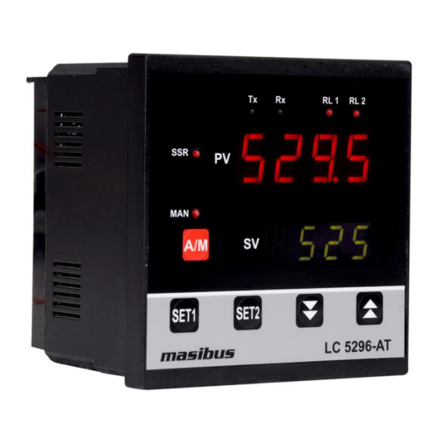
Display and Keypad Features
Describes the display types and key functions for the LC5296-AT model.
Available Output Types
Explains available output types: Relay, SSR, Linear, and Motor position control.
Communication and Power Supply Details
Specifies communication interface, protocol, baud rates, and power supply.
Environmental Conditions
Lists operating and storage temperature, humidity, and tempco limits.
Physical Dimensions and Mounting
LC5296-AT Physical Details
Provides physical dimensions, weight, material, and protection for LC5296-AT.
LC5248E-AT Physical Details
Details physical dimensions, weight, material, and protection for LC5248E-AT.
LC5296V-AT Physical Details
Specifies dimensions, weight, material, and protection for LC5296V-AT.
Terminal Connections Guide
LC5296-AT Terminal Layout
Illustrates and describes terminal connections for the LC5296-AT model.
LC5248E-AT Terminal Layout
Shows terminal connection details for the LC5248E-AT controller.
LC5296V-AT Terminal Layout
Provides terminal connection diagram and details for the LC5296V-AT.
Wiring Best Practices
Offers essential wiring guidelines and safety precautions for installation.
Front Panel Interface and Operations
LC5296-AT Front Panel Description
Details the parts and functions of the LC5296-AT front panel controls and indicators.
LC5248E-AT/LC5296V-AT Front Panel
Describes front panel components and functions for LC5248E-AT/LC5296V-AT.
Navigating the Controller Menu
LC5296-AT Menu Structure
Diagram illustrating the menu structure and parameter navigation for LC5296-AT.
LC5248E-AT/LC5296V-AT Menu Structure
Flowchart detailing the menu navigation for LC5248E-AT and LC5296V-AT models.
Run Time Functions
Explains how to view/change parameters like %Power and ambient temp in RUN mode.
Set Point and Auto Tune Configuration
Details parameters for setting Set Points and the Auto Tune function.
Configuration Mode Parameters
Lists configuration parameters for setting input type, output direction, etc.
Calibration Mode Settings
Parameters and settings related to instrument calibration procedures.
Control Functionality Explained
ON/OFF Control Operation
Explains the basic operation and hysteresis of the ON/OFF control mode.
PID Control and Auto Tuning
Details the Auto Tuning function and control parameters for PID control.
Ramp, Soak, and Motor Position Control
Describes functions for controlled set point changes and valve position control.
Alarm Output Configuration
Alarm Type Definitions
Lists and describes various alarm types like Deviation, Absolute Value, and PV error.
Calibration Procedures
CAL-zero and CAL-span Calibration
Steps for calibrating the zero and span of the instrument's PV input.
Retransmission Output Calibration
Procedure to calibrate retransmission output zero and span values.
Modbus RTU Communication Protocol
Protocol Introduction and Function Codes
Overview of connecting via RS-485 for Modbus RTU and function codes.
Parameter Address Mapping
Lists Modbus addresses for reading and writing controller parameters.
Handling Exceptional Responses
Explains error codes and responses for Modbus communication.
Appendix and Support
Troubleshooting Common Issues
Flowchart to diagnose and resolve issues with the controller's operation.
ON-OFF Logic and Output Tables
Details ON-OFF logic, and retransmission/linear output conditions.
Addon Card and Jumper Settings
Guide to jumper settings for output options and communication cards.
Load Connection and Electrical Precautions
Diagrams and recommendations for connecting loads and using snubbers.
Need help?
Do you have a question about the LC5248E-AT and is the answer not in the manual?
Questions and answers