Table of Contents
Advertisement
Quick Links
Strain Guage Indicator: 409-W
REF NO: m59A/om/501
Issue NO: 03
User's Manual
409-W
Strain Gauge Indicator
Masibus Automation and Instrumentation Pvt. Ltd.
B/30, GIDC Electronics Estate,
Sector-25, Gandhinagar-382044, Gujarat, India
Phone : +91-79-23287275/79.
Fax : +91-79-23287281.
Email: support@masibus.com
Web: www.masibus.com
Page 1 of 34
Advertisement
Table of Contents

Related Manuals for Masibus 409-W


Summary of Contents for Masibus 409-W
- Page 1 Strain Guage Indicator: 409-W REF NO: m59A/om/501 Issue NO: 03 User’s Manual 409-W Strain Gauge Indicator Masibus Automation and Instrumentation Pvt. Ltd. B/30, GIDC Electronics Estate, Sector-25, Gandhinagar-382044, Gujarat, India Phone : +91-79-23287275/79. Fax : +91-79-23287281. Email: support@masibus.com Web: www.masibus.com...
-
Page 2: Table Of Contents
Terminal Arrangement Diagram ........................7 Connection diagram for SGI Input ........................7 Configuration Guidelines ..................8 Menu Parameter List ............................8 Menu Layout for 409-W ..........................12 Main Menu for 409-W............................. 12 Calibration menu ............................. 14 Alarm Operation ....................15 Alarm type ............................... - Page 3 Strain Guage Indicator: 409-W REF NO: m59A/om/501 Issue NO: 03 Calibration ............................... 23 Communication Parameter ................... 26 Introduction ..............................26 Parameter Address Details ..........................26 Exceptional Response ............................28 Technical Specifications ..................29 10.1 Input Specification ............................29 10.2 Output Specifications ............................29 10.3 General Specifications .............................
-
Page 4: Introduction
Issue NO: 03 1. Introduction Product Overview/Description 409-W is a powerful micro-controller based strain gauge indicator, designed to accept strain gauges, load cells, force transducers, pressure transducers or similar devices as an input and two programmable set points with individual relays. Model 409-W is easy to operate and configuration is user friendly. -
Page 5: Front Panel Description
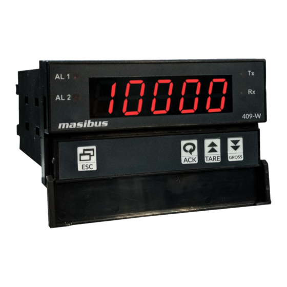
There are four keys for operation of the instruments. For understanding the operation first of all understand the functionality of keys as shown in Fig.1. Fig 3.1. Front Panel 409-W MENU key: It is used to come out from the main or sub menu. -
Page 6: Panel Cutout Dimension
Strain Guage Indicator: 409-W REF NO: m59A/om/501 Issue NO: 03 4. Panel Cutout Dimension Fig 4.1.Panel cut out for 409-W Page 6 of 34... -
Page 7: Sticker Details
Strain Guage Indicator: 409-W REF NO: m59A/om/501 Issue NO: 03 5. Sticker details Terminal Arrangement Diagram Fig 5.1. Terminal arrangement for 409-W Connection diagram for SGI Input Fig 5.2. Connection diagram for 409-W Page 7 of 34... -
Page 8: Configuration Guidelines
Strain Guage Indicator: 409-W REF NO: m59A/om/501 Issue NO: 03 6. Configuration Guidelines Menu Parameter List Default Display Name Description Value Set position of Decimal Point on Display. 0 : 0 RESO 1 : .0 Resolution (RESO) 2 : .00 3 : .000... - Page 9 Strain Guage Indicator: 409-W REF NO: m59A/om/501 Issue NO: 03 Retransmission Output Type This output is according to PV input. Zero & Span acts as Min & Max value of retransmission o/p RETmA scale respectively. Retransmission current (rEtma) 0 : 4-20mA...
- Page 10 Strain Guage Indicator: 409-W REF NO: m59A/om/501 Issue NO: 03 0.001 to 0.255 Resolution = 0.000 0.0001 to 0.0255 Resolution = 0.0000 Set Control O/P & Retransmission state when Input OPEN condition. OPES OPEN Sensor Status 0 : UP (opes)
- Page 11 Strain Guage Indicator: 409-W REF NO: m59A/om/501 Issue NO: 03 (brHt) 10 to 100 F-CNT IIR Filter is apply for sated count only. Filter count (F-CNT) 0-500 ALPHA Set alpha for IIR Filter. Alpha (ALPHA) 0-100 M-CNT Moving Average Filter is apply for sated count only.
-
Page 12: Menu Layout For 409-W
Strain Guage Indicator: 409-W REF NO: m59A/om/501 Issue NO: 03 Note 2: * maximum mV read from input, select 1. 15mV for 0-15mV 2. 30mV for 0-30mV 3. 75mV for 0-75mV Note 3: ** initial settings Parameters Set value Resolution 0.00... - Page 13 Strain Guage Indicator: 409-W REF NO: m59A/om/501 Issue NO: 03 Page 13 of 34...
-
Page 14: Calibration Menu
Strain Guage Indicator: 409-W REF NO: m59A/om/501 Issue NO: 03 Calibration menu Theoretical mV calibration method Sample weight calibration method Page 14 of 34... -
Page 15: Alarm Operation
Strain Guage Indicator: 409-W REF NO: m59A/om/501 Issue NO: 03 7. Alarm Operation Alarm type HH-high, very high AL1-high, AL2-very high HL-high, low AL1-low, AL2-high. LL-very low, low AL1-very low, AL2-low. This setting is common for all groups. Status of ALARM/TRIP It will toggle between ALARM and TRIP depending up on selection in menu. -
Page 16: Hl Logic
Strain Guage Indicator: 409-W REF NO: m59A/om/501 Issue NO: 03 If PV<SP2-Hyst2 but, >SP1 => Relay 1-ON, Relay 2-OFF. Depending up on condition set i.e. Latch Yes/No, Acknowledge Yes/No or Trip refer table 7.4, 7.5, 7.6, 7.7. HL Logic HL-high,low AL1-low, AL2- high Fig 7.2. -
Page 17: Open Sensor Up Scale/Down Scale
Strain Guage Indicator: 409-W REF NO: m59A/om/501 Issue NO: 03 Relay 2-ON till PV>SP2+HYS2 after that Relay 2- OFF. Fig 7.3. Depending upon condition set i.e. Latch Yes/No, Acknowledge Yes/No or Trip refer tables 7.4, 7.5, 7.6, 7.7. Open sensor UP scale/DOWN scale This is used to define the state of the alarms in OPEN sensor condition. -
Page 18: Ll Logic
Strain Guage Indicator: 409-W REF NO: m59A/om/501 Issue NO: 03 7.10 LL Logic LL-low, low AL1-very low, AL2-low. In this logic if “UP Scale” condition has been selected than in OPEN sensor condition ALARM 1 and ALARM 2 will be in the NORMAL condition and will work according to the following tables 7.4, 7.5, 7.6, 7.7.If “DOWN Scale”... -
Page 19: Relay Delay
Strain Guage Indicator: 409-W REF NO: m59A/om/501 Issue NO: 03 7.13 Relay Delay Relay delay is the parameter used to set the delay (second) in the operation of relays (both 1&2).Minimum value of delay is 0(second) and maximum value 9999 (second) can be configured using keyboard. - Page 20 Strain Guage Indicator: 409-W REF NO: m59A/om/501 Issue NO: 03 LAMP FLASH FLASH Trip RELAY Table 7.4. Alarm AL2 (Momentary Alarm): when in abnormal condition ACK not pressed. Condition Normal Abnormal DOWN ACK** Normal* ACK*** Alarm LAMP FLASH FLASH FLASH...
- Page 21 Strain Guage Indicator: 409-W REF NO: m59A/om/501 Issue NO: 03 Alarm LAMP FLASH FLASH STEADY High Latch(No) RELAY LAMP FLASH STEADY STEADY Trip RELAY Alarm LAMP FLASH FLASH STEADY STEADY Latch(Yes) RELAY Alarm LAMP FLASH FLASH STEADY Latch(No) RELAY LAMP...
- Page 22 Strain Guage Indicator: 409-W REF NO: m59A/om/501 Issue NO: 03 Latch(No) RELAY LAMP FLASH STEADY STEADY Trip RELAY LAMP FLASH FLASH STEADY STEADY Alarm Latch(Yes) RELAY Alarm LAMP FLASH FLASH STEADY Latch(No) RELAY LAMP FLASH STEADY STEADY Trip RELAY Table 7.7.
-
Page 23: Calibration Procedure
Strain Guage Indicator: 409-W REF NO: m59A/om/501 Issue NO: 03 8. Calibration Procedure Calibration The calibration in the instrument is using front panel keys as well as with Modbus communication. Instrument can be calibrated even during installed condition. Calibration is carried out using following steps. - Page 24 Strain Guage Indicator: 409-W REF NO: m59A/om/501 Issue NO: 03 Calibration using keys: Enter into CALIB mode with front panel keys, Zero Calibration: feed zero weight and Press Span calibration: feed span weight and press Calibration using Modbus: Modbus address 40099 Zero Calibration: feed zero weight and write “1”...
- Page 25 Strain Guage Indicator: 409-W REF NO: m59A/om/501 Issue NO: 03 • Sensitivity: 2mV/V • Maximum load: 4000.0kg Set calibration parameters as shown below: SPAN = 4000.0 kg MV-FS = 20.000 mV Zero weight is empty scale weight. Enter into CALZ mode with front panel keys, Zero Calibration: Feed empty scale mV and Press 3.
-
Page 26: Communication Parameter
Strain Guage Indicator: 409-W REF NO: m59A/om/501 Issue NO: 03 9. Communication Parameter Introduction The unit can be connected in RS-485 communication data link either in multi drop or repeat mode. Each unit must have unique Serial Number. Entire range of addresses (1 to 247) may be used. - Page 27 Strain Guage Indicator: 409-W REF NO: m59A/om/501 Issue NO: 03 Process value 30051 Swapped Long -19999 99999 Gross value 30053 Swapped Long -19999 99999 30055 Swapped Long Reserved for future 40001 Integer Reserved for future 40002 Integer Set point 1...
-
Page 28: Exceptional Response
Strain Guage Indicator: 409-W REF NO: m59A/om/501 Issue NO: 03 *Parity and stop bit 40047 Unsigned char *Step value 40048 Integer Process value 40051 Swapped Long -19999 99999 Set point 1 40053 Swapped Long -19999 99999 Set point 2 40055... -
Page 29: Technical Specifications
Strain Guage Indicator: 409-W REF NO: m59A/om/501 Issue NO: 03 Illegal data value. A value contained in the query data field is not an allowable value for the salve. When Master device write some parameters to Slave device, If slave device busy then it will send 06 code to indicate slave device is busy. -
Page 30: General Specifications
Strain Guage Indicator: 409-W REF NO: m59A/om/501 Issue NO: 03 Accuracy ±0.25% of full Span (one at a time factory settable). <=600 Ω Load Resistance for current O/P Load Resistance for Voltage O/P >=2 KΩ ALARM -Momentary Alarm Condition – high/low/vlow Alarm AL1 Lamp –... -
Page 31: Power Supply
Strain Guage Indicator: 409-W REF NO: m59A/om/501 Issue NO: 03 10.4 Power Supply 85 to 265VAC @50HZ / 100-300VDC, 18 to 36VDC(One at a Power Supply time factory settable) Power Consumption Max. 10VA Load excitation voltage 5 V,10 V,12V,15V DC(±1%) @100mA(±1 % accuracy) 10.5 Isolation... -
Page 32: Special Feature
Strain Guage Indicator: 409-W REF NO: m59A/om/501 Issue NO: 03 10.7 10.7Special Feature Digital Filter 60 Sec. Scalability Input and output Scalability for SGI input Rx output mapping According to Net and Gross value On demand display value Gross,mV Digital Input... -
Page 33: Jumper Location For Retransmission Output
Strain Guage Indicator: 409-W REF NO: m59A/om/501 Issue NO: 03 11.2 Jumper Location for Retransmission Output Fig 7. Jumper Location for Retransmission output For V retransmission output short the 1 and 2 pins of jumpers JP8 and JP9 of AO card as shown in figure 7. -
Page 34: What Is Tare Weight
Strain Guage Indicator: 409-W REF NO: m59A/om/501 Issue NO: 03 Net Value = Gross Value- Tare Value Example: If Input Range is 0-20mV, selected 30mV group. If Scaled Display Range is 0.00-40.00Kg., then I/P Zero will be 0.00 and I/P Span will be 40.00 with resolution 0.00.
Need help?
Do you have a question about the 409-W and is the answer not in the manual?
Questions and answers