Table of Contents
Advertisement
Masibus Automation & Instrumentation Pvt. Ltd.
B/30, GIDC Electronics Estate,
Sector-25, Gandhinagar-382044, Gujarat, India
+91 79 23287275-79
Email: support@masibus.com
Web: www.masibus.com
User's Manual
O
N
-
O
F
O
N
-
O
F
+91 79 23287281-82
F
C
O
N
T
R
O
L
L
E
R
F
C
O
N
T
R
O
L
L
E
R
L
C
5
2
9
6
L
C
5
2
9
6
L
C
5
2
9
6
-
H
L
C
5
2
9
6
-
H
5
0
0
6
-
R
N
5
0
0
6
-
R
N
L
C
5
2
4
8
E
L
C
5
2
4
8
E
I
N
D
I
C
A
T
O
R
I
N
D
I
C
A
T
O
R
4
0
8
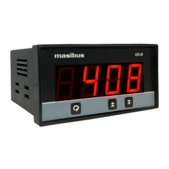
-
M
4
0
8
-
M
Advertisement
Table of Contents

Related Manuals for Masibus 5006-RN


Summarization of Contents
1. Introduction
Product Ordering Code
Explains how to identify the product model and its configuration.
Safety Precautions
Important safety warnings and guidelines for using the product safely.
2. Specifications
2.1 Inputs
Details of input signal types, ranges, accuracy, and resolution.
2.2 Display & Keys
Description of the front panel display elements and operational keys.
2.3 Output Types
Information on available relay and retransmission output types.
3. Physical Specifications & Mounting Details
3.1 LC5296 / 5006-RN
Physical dimensions and mounting details for LC5296 and 5006-RN models.
3.2 LC5296-H / 408-M
Physical dimensions and mounting details for LC5296-H and 408-M models.
3.3 LC5248E
Physical dimensions and mounting details for the LC5248E model.
4. Terminal Connections
4.1 LC5296 & 5006-RN
Terminal connection details and descriptions for LC5296 and 5006-RN.
4.2 LC5296-H / 408-M
Terminal connection details and descriptions for LC5296-H and 408-M.
4.5 How to connect wires?
Guidelines and precautions for proper wiring of the instrument.
5. Front Panel Details
5.1 Front Panel Description for LC5296, LC5296-H, 5006-RN & LC5248E
Description of front panel components for specified models.
5.2 Front Panel Description for 408-M
Description of front panel components specific to the 408-M model.
6. Menu Layout for LC5296, LC5296-H, 5006-RN, LC5248E
6.1 Run Time Indication/Function
Parameters that can be viewed or changed during run time.
6.2 Set Point Setting
Configuration of set point values for the controller.
6.3 Configuration Mode
Main configuration menu for setting various operational parameters.
6.4 Calibration Mode
Procedures for calibrating the instrument's inputs and outputs.
7. Menu Layout for 408-M
7.2 Menu Layout for 408-M
Menu structure overview for the 408-M model.
7.3 Run Time Indication/Function
Parameters that can be viewed or changed during run time.
7.5 Configuration Mode
Configuration settings specific to the 408-M model.
7.6 Calibration Mode
Calibration procedures specific to the 408-M model.
8. Control Function
8.1 ON/OFF Control
Explanation of ON/OFF control logic, including hysteresis.
9. Calibration Procedure
9.1 Procedure for CAL-zero and CAL-span
Steps for performing zero and span calibration on the instrument.
9.2 Procedure for RET-zero and RET-span
Steps for calibrating retransmission zero and span outputs.
10. Communication Protocol-Modbus RTU
10.1 Introduction
Overview of Modbus RTU communication for data exchange.
10.2 Parameter Address Details
Table listing Modbus parameters, addresses, and access types.
11. Appendix
11.1 Troubleshooting
Guide to diagnose and resolve common operational issues.
11.2 On-Off Logic
Table describing the states of relays and LEDs for ON-OFF logic.
11.3 Retramission Output Table for Open /Over/Under Condition
Table detailing retransmission output values for specific conditions.
11.4 Jumper Settings for Add-on Card Selection & Retransmission
Jumper configurations for selecting output options and cards.
11.5 Load connection
Guidelines for connecting loads and using snubbers for protection.
Electrical Precautions During Use
Warnings about electrical noise and protecting the instrument from damage.
Need help?
Do you have a question about the 5006-RN and is the answer not in the manual?
Questions and answers