Table of Contents
Advertisement
S
S
Masibus Automation & Instrumentation Pvt. Ltd.
B/30, GIDC Electronics Estate,
Sector-25, Gandhinagar-382044, Gujarat, India
+91 79 23287275-
Email: support@masibus.com
Web: www.masibus.com
I
N
G
L
E
L
O
O
I
N
G
L
E
L
O
O
User's Manual
P
P
I
D
C
O
N
P
P
I
D
C
O
N
w
i
t
h
A
U
w
i
t
h
A
U
T
R
O
L
L
E
R
T
R
O
L
L
E
R
T
O
T
U
N
E
T
O
T
U
N
E
5
0
4
0
5
0
4
0
-82
Advertisement
Table of Contents

Related Manuals for Masibus 5040


Summary of Contents for Masibus 5040
- Page 1 User’s Manual Masibus Automation & Instrumentation Pvt. Ltd. B/30, GIDC Electronics Estate, Sector-25, Gandhinagar-382044, Gujarat, India +91 79 23287275- Email: support@masibus.com Web: www.masibus.com...
-
Page 2: Table Of Contents
PID CONTROLLER -5040 REF NO: m53A/om/101 Issue NO: 08 Contents 1. INTRODUCTION .................. 4 Foreword ........................ 4 Notice ........................4 Trademarks ......................4 Checking the Contents of the Package ..............4 Product Ordering Code ..................4 List of Accessories ....................5 Safety Precautions .................... - Page 3 PID CONTROLLER -5040 REF NO: m53A/om/101 Issue NO: 08 6.6 LEVEL - 4 ...................... 24 6.7 LEVEL – 5 ..................... 26 6.8 Calibration ..................... 27 6.9 Factory Reset Parameters ................28 7. PARAMETER FLOW CHART ............30 8. ALARMS & DIGITAL OUTPUTS ............33 9.
-
Page 4: Introduction
REF NO: m53A/om/101 Issue NO: 08 1. INTRODUCTION Foreword Thank you for purchasing 5040 series PID controller. This manual describes the basic functions and operation methods of 5040.Please read through this user’s manual carefully before using the product. Notice The contents of this manual are subject to change without notice as a result of continues improvements to the instrument’s performance and functions... -
Page 5: List Of Accessories
PID CONTROLLER -5040 REF NO: m53A/om/101 Issue NO: 08 The Single Loop Controller unit has a nameplate affixed to the one side of the enclosure.Check the model and suffix codes inscribed on the nameplate to confirm that the product received is that which was ordered. -
Page 6: Installation Details
PID CONTROLLER -5040 REF NO: m53A/om/101 Issue NO: 08 2. INSTALLATION DETAILS 2.1 How to Install Mounting method: Panel mounting To install the controller select a location where: no one may accidentally touch the terminals mechanical vibrations are minimal ... -
Page 7: External Dimensions And Panel Cutout Dimensions
PID CONTROLLER -5040 REF NO: m53A/om/101 Issue NO: 08 2.2 External Dimensions and Panel Cutout Dimensions Unit: mm User’s Manual Page 7 of 53... -
Page 8: How To Connect Wires
PID CONTROLLER -5040 REF NO: m53A/om/101 Issue NO: 08 2.3 How to connect wires Before carrying out wiring, turn off the power to the controller and check that the cables to be connected are not alive because there is a possibility of electric shock. -
Page 9: Hardware Specification Details
PID CONTROLLER -5040 REF NO: m53A/om/101 Issue NO: 08 3. HARDWARE SPECIFICATION DETAILS 3.1 Inputs Analog Input Input Type Thermocouple (E, J, K, T, B, R, S, N), RTD (Pt100), Current, Voltage Display Range Table-3.1 Accuracy TC, RTD: ± 0.1% of F.S ± 1 degC Current, Voltage: ±... -
Page 10: Display & Keys
PID CONTROLLER -5040 REF NO: m53A/om/101 Issue NO: 08 Digital Input No of DI Input Type Non-Voltage Contact or Pulse Input(24VDC,@5mA) Rating 24VDC@5mA Max Purpose Target Set point selection, Auto/Manual selection, Remote /Local mode switching, Run/Stop mode selection Minimum status detection Holds... -
Page 11: Communication Details
PID CONTROLLER -5040 REF NO: m53A/om/101 Issue NO: 08 Control Output (Field Programmable) Relays 1 (Relay-1) for Relay and ON-OFF Output Type 2 (Relay-1 & Relay-2) for VPFB & VPFN Output Type Type Single Change over (C, NO, NC) Rating... -
Page 12: Power Supply
PID CONTROLLER -5040 REF NO: m53A/om/101 Issue NO: 08 3.5 Power Supply Standard 85-265VAC/ 100-300VDC Optional 18-36VDC Power consumption <12 VA Isolation (Withstanding voltage) Between primary terminals* and secondary terminals**: At least 1500 V AC for 1 minute ... -
Page 13: Wiring Diagram
PID CONTROLLER -5040 REF NO: m53A/om/101 Issue NO: 08 4. WIRING DIAGRAM 4.1 BACK PLATE WIRING DETAIL User’s Manual Page 13 of 53... -
Page 14: Trasmitted Power Supply Wiring Diagram
PID CONTROLLER -5040 REF NO: m53A/om/101 Issue NO: 08 4.2 TRASMITTED POWER SUPPLY WIRING DIAGRAM 4.3 VALVE POSITION FEEDBACK WIRING (FOR INTERLOCK FORWARD AND REVERSE RELAY) User’s Manual Page 14 of 53... -
Page 15: Front Panel Details
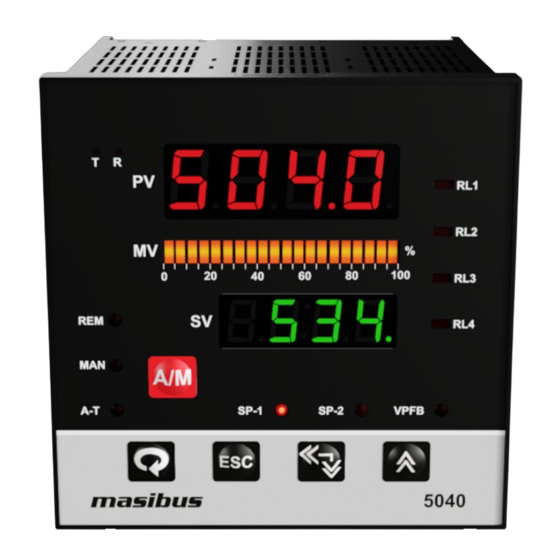
PID CONTROLLER -5040 REF NO: m53A/om/101 Issue NO: 08 5. FRONT PANEL DETAILS Name of Part Function Process Value Display process value. Display(PV) Display parameter name when userset parameter. Display error message when an error occurs. Set Value Display Display set value. -
Page 16: Key Function Description
PID CONTROLLER -5040 REF NO: m53A/om/101 Issue NO: 08 Name of Part Function Set Point – 1 (SP-1) Indicator lamp will on when Set Point 1 is selected. All controller action with respect to SP-1 Set Point – 2(SP-2) Indicator lamp will on when Set Point 2 is selected. All... - Page 17 PID CONTROLLER -5040 REF NO: m53A/om/101 Issue NO: 08 Example: How to change SET POINT:- SP.1 and SP.2 will be shown in operator mode if they are selected in one of the SELECT Display Parameter from LEVEL-5 Menu. Here SELECT display 1(D.S.1) is set forSP-1and SELECT display 2(D.S.2)is set forSP-2and D.T.1 &...
-
Page 18: Menu Layout
PID CONTROLLER -5040 REF NO: m53A/om/101 Issue NO: 08 6. MENU LAYOUT 6.1 RUN TIME INDICATION/FUNCTION Following parameters can view or change during run time. Press Shift/Dec key to show percentage power (0.0 to 100.0%) For Thermocouple input type, Press Inc key to show ambient temperature. -
Page 19: Level - 2
PID CONTROLLER -5040 REF NO: m53A/om/101 Issue NO: 08 Not available Integral Time 0 to 1000 seconds for Output type (ti) OnOF Not available Derivative Time 0 to 250 seconds for Output type (td) OnOF Not available d . fCt Derivative Factor 0.01 to 1.00... - Page 20 PID CONTROLLER -5040 REF NO: m53A/om/101 Issue NO: 08 Level-2) A1 . SP Alarm 1 Set point PV range selected (A1.SP) A1 . tP 0 to 18. Refer alarm Alarm 1 Type 0 (none) type Table-8.1 (A1.tP) A1 . HY...
- Page 21 PID CONTROLLER -5040 REF NO: m53A/om/101 Issue NO: 08 (d1.SP) point d1 . tP Digital Output 1 0 to 18. Refer alarm 0(none) Type type Table-8.1 (d1.tP) d1 . HY Digital Output 1 1 to 250 Hystresis (d1.HY) norm/ flsf d1 .
-
Page 22: Level - 3
PID CONTROLLER -5040 REF NO: m53A/om/101 Issue NO: 08 6.5 LEVEL - 3 Pressing MENU key PV for 3 seconds (approx.) Display shows Mode (mode) message. SV display shows Lvl3 (LvL3) Use Inc key to move to other menu levels. -
Page 23: Pid Controller
PID CONTROLLER -5040 REF NO: m53A/om/101 Issue NO: 08 Dir/ rev o . dir Output (Cool / Heat) 1:(dir) Direction (Dir / Rev) (o.dir) 0:(rev) Pid type Motor Travel Time selected is M . tim (position proportional 10 to 500 sec valve position (m.tim) -
Page 24: Level - 4
PID CONTROLLER -5040 REF NO: m53A/om/101 Issue NO: 08 6.6 LEVEL - 4 Pressing MENU key for 3 seconds (approx.) PV Display shows Mode (mode) message. SV display shows Lvl4 (LvL4) Use Inc key to move to other menu levels. - Page 25 PID CONTROLLER -5040 REF NO: m53A/om/101 Issue NO: 08 2:(0 - 5) – 0 – 5volt 3:(1 - 5) – 1 – 5volt 4:(0 – 10) - 0 -10volt SP/PV/Co/Zv 0:(SP) – Set point 1:(Pv) –Process Rtr . v Retransmission value 2:(CO) –...
-
Page 26: Level -5
PID CONTROLLER -5040 REF NO: m53A/om/101 Issue NO: 08 6.7 LEVEL –5 Pressing MENU key for 3 seconds (approx.) PV Display shows Mode (mode) message. SV display shows Lvl5(LvL5) Use Inc key to move to other menu levels. Press set key again to scroll through the menu items of particular level. -
Page 27: Calibration
PID CONTROLLER -5040 REF NO: m53A/om/101 Issue NO: 08 R / r-w d . 5 . t Display 5 Parameter 0: r-w: Read+ write Type (D.5.T) 1:R: Read only d . s . 6 SELECT display 6 0 to 91 (D.S.6) -
Page 28: Factory Reset Parameters
PID CONTROLLER -5040 REF NO: m53A/om/101 Issue NO: 08 (tc.L.S) Linear Span sensor type selected is T/c or Linear Calibtriaon Rtd . z PV Sensor Calibration Zero type is RTD FOR RTD Input (rtd.Z) Rtd . S PV Sensor Calibration Span... - Page 29 PID CONTROLLER -5040 REF NO: m53A/om/101 Issue NO: 08 PARA (CAL)\(PARA) CAL- Only calibration L . def LOAD Def ault set to default value (L.dEF) PARA- All parameters excluding calibration will set to default value Note: - Factory reset will load default parameters, as mention in MENU LAYOUT (Default value).
-
Page 30: Parameter Flow Chart
PID CONTROLLER -5040 REF NO: m53A/om/101 Issue NO: 08 7. PARAMETER FLOW CHART User’s Manual Page 30 of 53... - Page 31 PID CONTROLLER -5040 REF NO: m53A/om/101 Issue NO: 08 User’s Manual Page 31 of 53...
- Page 32 PID CONTROLLER -5040 REF NO: m53A/om/101 Issue NO: 08 NOTE: It is important that the controller be set up in proper manner. Failure to do so could result in incorrect operation, as changing some parameters will change other related functions.
-
Page 33: Alarms & Digital Outputs
PID CONTROLLER -5040 REF NO: m53A/om/101 Issue NO: 08 8. ALARMS & DIGITAL OUTPUTS For all Alarm and Digital outputs (open collector) there are five settings. (AS shown in LEVEL – 2 Menu) Set Value Type Hystresis ... - Page 34 PID CONTROLLER -5040 REF NO: m53A/om/101 Issue NO: 08 Hystresis : Hystresis application is shown in the figure. Direction: All the figures here are shown considering the setting is Normal. If the settings are Fail Safe, the relays will behave exactly the opposite way. However, it’s worth mentioning that the relays will be in off (de-energized state on Power on / reset condition).
- Page 35 PID CONTROLLER -5040 REF NO: m53A/om/101 Issue NO: 08 A time delay can be provided for the actual output. Effects of delay are illustrated in the diagram below. Blinking Indication time Relay On / Close Contact O/p. Off / Open...
-
Page 36: Digital Inputs
PID CONTROLLER -5040 REF NO: m53A/om/101 Issue NO: 08 9.DIGITAL INPUTS There are four digital inputs for various purposes. To achieve these functions through field contact, user has to select for particular digital input in Level – 3mode. Digital Input – 1: SET POINT-1 / SET POINT-2 SELECTIONS If target set point number has been switched using contact input, when the Di-1 Set to YES, that function cannot be selected by keystroke. -
Page 37: Control Function Details
PID CONTROLLER -5040 REF NO: m53A/om/101 Issue NO: 08 10. CONTROL FUNCTION DETAILS Direct/ReverseControl (Output Direction): For Heat (Reverse Action) and Cool (Direct Action) type PID control logic, user has to program the proportional band, integral time and derivative time for proper control. - Page 38 PID CONTROLLER -5040 REF NO: m53A/om/101 Issue NO: 08 AUTO TUNE FUNCTION: Auto Tuning is a function with which the controller automatically measures the process characteristics to automatically set the optimum PID constants. Limit Cycle method is used to calculate the PID values.
- Page 39 PID CONTROLLER -5040 REF NO: m53A/om/101 Issue NO: 08 Manual Reset: Virtually no process requires precisely 50% output on single output controls or 0% output on two output controls. Because of this many older control designs incorporated an adjustment called manual reset (also called offset on some controls).
- Page 40 PID CONTROLLER -5040 REF NO: m53A/om/101 Issue NO: 08 P ACTION: - I ACTION:- D ACTION:- Digital Filter (FLTR):- In certain application the process value is too unstable to be read. To improve this, a programmable low pass filter incorporated in the controller can be used. This is a first order IIR filter with time constant specified by FLTR (FLTR) parameter of LEVEL-3.
- Page 41 PID CONTROLLER -5040 REF NO: m53A/om/101 Issue NO: 08 Position Proportional Control: Position proportional control can be of either feedback type or estimating type. In feedback type position proportional control, the controller obtains a valve position signal from a feedback slide wire resistor attached to a valve.
-
Page 42: Calibration Procedure
PID CONTROLLER -5040 REF NO: m53A/om/101 Issue NO: 08 USE TO Without feedback USE TO CONTROL CONTROL ALARM3 ALARM4 Action FORWARD RELAY REVERSE RELAY 11. CALIBRATION PROCEDURE Calibration is provided for ambient temperature, PV sensor input, Remote set point, Control output, Retransmission output and Position feedback potentiometer. -
Page 43: Remote Set Point Calibration
PID CONTROLLER -5040 REF NO: m53A/om/101 Issue NO: 08 Inc/Shift key to arrive at the desired process value. Press ENT key to register the changes. wait The controller will display message (wait) in the SV display to indicate that it is doing the necessary calculations. -
Page 44: Retransmission Output Calibration (Voltage/Current Output)
PID CONTROLLER -5040 REF NO: m53A/om/101 Issue NO: 08 key. The controller will store zero calibration value. Press MENU key for span calibration. pfb.S PV shows the message (position feedback span calibration). SV display shows value corresponding to signal input value and old calibration data. Feed signal input using a calibrator, such that process value is close to signal’s upper range value. -
Page 45: Communication Details
PID CONTROLLER -5040 REF NO: m53A/om/101 Issue NO: 08 NOTE: If you calibrate any input from any group i.e. I/P E-TC from Group – 1 than calibration is not required for other input types from Group-1. 12. COMMUNICATION DETAILS The MODBUS Communications protocol as RS-485 interface module is installed. Only RTU mode is supported. - Page 46 PID CONTROLLER -5040 REF NO: m53A/om/101 Issue NO: 08 Modbus parameters :( Absolute Address 40001 to 40100) Absolu Data Minimum Maximum Access Parameter addres Type value value Type Input type Input type Set Point – 1 40001 Integer range low...
- Page 47 PID CONTROLLER -5040 REF NO: m53A/om/101 Issue NO: 08 DO2 DLY 40046 Char DO3 SP 40047 Integer -1999 9999 DO3 TP 40048 Char DO3 HYS 40049 Integer DO3 DIR 40050 Char DO3 DLY 40051 Char DO4 SP 40052 Integer -1999...
- Page 48 PID CONTROLLER -5040 REF NO: m53A/om/101 Issue NO: 08 Type Retransmission 40089 Char Variable Retransmission 40090 Char Direction Retransmission 40091 Integer -5.0% 105.0% Range high Retransmission 40092 Integer -5.0% 105.0% Range low Auto tune Hys 40093 Char Time out 40094 Char Lock –...
-
Page 49: Appendix
PID CONTROLLER -5040 REF NO: m53A/om/101 Issue NO: 08 13. Appendix 13.1 Troubleshooting If the operating display does not appear after turning on the controller’s power, follow the measures in the procedure below. If a problem appears complicated, contact our sales representative. -
Page 50: Rsp (Remote Set Point)Burnout Condition
PID CONTROLLER -5040 REF NO: m53A/om/101 Issue NO: 08 TC-K OPEN TC-T OPEN TC-N OPEN TC-B OPEN TC-R OPEN TC-S OPEN PT 100(RTD) OPEN 0-10V DC OPEN 0 to 5V DC OPEN 1 to 5V DC OPEN 0 to 2V DC OPEN 0.4 to 2V DC... -
Page 51: Retramission Output Table For Open /Over /Under Condition
PID CONTROLLER -5040 REF NO: m53A/om/101 Issue NO: 08 100Ω-POT to pFB.E((PFB.E) 1KΩ-POT NOTE: 20-segment LED BAR will start to blink to indicate that Position Feedback input is not connected properly in Run mode. In calibration mode, SV display shows PFb.E (PFB.E) (Position Feedback Error). -
Page 52: Control Output Table Open/Over/ Under Condition
PID CONTROLLER -5040 REF NO: m53A/om/101 Issue NO: 08 1) For Retransmission output type 0-20mamp, 0-10v, 1-5v and 0-5v also applicable according to above table. 2) For 0-20mamp, 0-10v and 0-5v minimum output value will be 0mamp and 0v respectively. -
Page 53: User's Manual
PID CONTROLLER -5040 REF NO: m53A/om/101 Issue NO: 08 13.7 Digital Input & Retransmission Output Type Selection Settings In this Model Digital Input & Retransmission Output come with the two different types Digital Input as Retransmission Output as - Non-Voltage Contact Switch...
Need help?
Do you have a question about the 5040 and is the answer not in the manual?
Questions and answers