Table of Contents
Advertisement
Quick Links
Advertisement
Table of Contents

Related Manuals for Masibus LC5296-XP-DC


Summary of Contents for Masibus LC5296-XP-DC
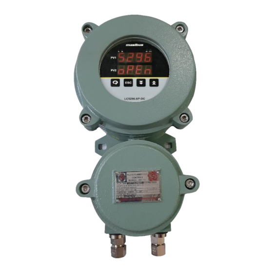
- Page 1 User’s Manual FLAMEPROOF CONTROLLER LC5296-XP-DC Masibus Automation & Instrumentation Pvt. Ltd. B/30, GIDC Electronics Estate, Sector-25, Gandhinagar-382044, Gujarat, India +91 79 23287275-77 +91 79 23287281 Email: support@masibus.com Web: www.masibus.com...
-
Page 2: Table Of Contents
4.1 How to connect wires ..................12 5. FRONT PANEL DETAILS ................... 13 5.1 Front Panel Description .................. 13 6. MENU LAYOUT for LC5296-XP-DC ..............14 6.1 RUN Time Indication/Function................ 16 6.2 Set Point Setting ..................... 16 6.3 CONFIGURATION MODE................16 6.4 MAP MODE .................... - Page 3 Model: LC5296-XP-DC Doc. Ref. no.:- m61D/om/401 Issue no.: 05 7.1 ON/OFF Control ..................... 22 8. CALIBRATION PROCEDURE ................23 8.1 Procedure for CAL-zero and CAL-span ............23 8.2 Procedure for RET-zero and RET-span ............24 9. COMMUNICATION PROTOCOL–MODBUS RTU ..........24 9.1 INTRODUCTION ....................
-
Page 4: Introduction
Every effort has been made to ensure accuracy in the preparation of this manual. Should any errors or omissions come to your attention, however, please inform MASIBUS Sales office or sales representative. Under no circumstances may the contents of this manual, in part or in whole, be transcribed or copied without our permission. -
Page 5: Specifications
Model: LC5296-XP-DC Doc. Ref. no.:- m61D/om/401 Issue no.: 05 2. SPECIFICATIONS 2.1 Inputs Analog Input Input 1 Type RTD (Pt100), Current, Voltage, Serial Input 2 Type RTD (Pt100), Current, Voltage,Serial Display Range Refer Table-2.1 Accuracy + (0.25% of FS+ 1 degree) for RTD input. -
Page 6: Output Types
Also, Output Direction [Direct (Cooling) /Reverse (Heating)] is selectable from software. At a time unit can support Relay or SSR Output. (Factory settable)(Specify in Order Code) Relay Output Relays 2 (For LC5296-XP-DC) Type Single Change over Three Terminals (C, NO, NC) Rating 2A @ 230VAC / 30VDC... -
Page 7: Environmental Conditions
Model: LC5296-XP-DC Doc. Ref. no.:- m61D/om/401 Issue no.: 05 Isolation (Withstanding voltage) Between primary terminals* and secondary terminals**: At least 1500 V AC for 1 minute Between primary terminals* and grounding terminal: At least 1500 V AC for 1 minute ... -
Page 8: Physical Specifications & Mounting Details
Model: LC5296-XP-DC Doc. Ref. no.:- m61D/om/401 Issue no. 05 3. PHYSICAL SPECIFICATIONS & MOUNTING DETAILS 3.1 External Dimensions Unit: mm Mounting method: Wall Mounting Unit: mm Weight: Approx. 3 Kg. Type of Protections: Flameproof (Explosion Proof) EX-d Area Classification: Hazardous Location of Zone 1 & 2 Gas Groups: IIA, IIB &... - Page 9 Model: LC5296-XP-DC Doc. Ref. no.:- m61D/om/401 Issue no.: 05 FRONT VIEW OF LC5296-XP-DC INTERNAL VIEW WITH TERMINAL CONNECTION DETAILS SIDE VIEW FOR CABLE ENTRY Page 9 of 31 User’s Manual...
-
Page 10: External Dimensions & For Dual Compartment Enclosure
Model: LC5296-XP-DC Doc. Ref. no.:- m61D/om/401 Issue no. 05 3.2 External Dimensions & for dual compartment enclosure Unit: mm Mounting method: Wall Mounting Weight: Approx. 6Kg. Type of Protections: Flameproof (Explosion Proof) EX-d Area Classification: Hazardous Location of Zone 1 & 2... -
Page 11: Terminal Connections
Model: LC5296-XP-DC Doc. Ref. no.:- m61D/om/401 Issue no.: 05 4. TERMINAL CONNECTIONS 4.1 Single compartment enclosure 4.2 Dual compartment enclosure Terminal No. Description For Relay-2 potential free Contacts (Use 230V -2A load) 1 (C2) 2 (NO2) ON-OFF control... -
Page 12: How To Connect Wires
Model: LC5296-XP-DC Doc. Ref. no.:- m61D/om/401 Issue no. 05 4.1 How to connect wires Before carrying out wiring, turn off the power to the controller and check that the cables to be connected are not alive because there is a possibility of electric shock. -
Page 13: Front Panel Details
Model: LC5296-XP-DC Doc. Ref. no.:- m61D/om/401 Issue no.: 05 5. FRONT PANEL DETAILS 5.1 Front Panel Description Name of Part Symbol Function Enter into Edit Mode. Increment Key Increment the Value of any Parameter in edit mode. Enter into Edit Mode. -
Page 14: Menu Layout For Lc5296-Xp-Dc
Model: LC5296-XP-DC Doc. Ref. no.:- m61D/om/401 Issue no. 05 6. MENU LAYOUT for LC5296-XP-DC Page 14 of 31 User’s Manual... - Page 15 Model: LC5296-XP-DC Doc. Ref. no.:- m61D/om/401 Issue no.: 05 MENU LAYOUT for LC5296-XP-DC Page 15 of 31 User’s Manual...
-
Page 16: Run Time Indication/Function
Model: LC5296-XP-DC Doc. Ref. no.:- m61D/om/401 Issue no. 05 6.1 RUN Time Indication/Function Following parameters can view or change during run time. In upper display, it shows Process value for input-1. In lower display, it shows Process value for input-2. - Page 17 Model: LC5296-XP-DC Doc. Ref. no.:- m61D/om/401 Issue no.: 05 Automatically change to the Input Higher Range with changing of Input Type 850.0 SPN.1 (Refer Above Table) Span-1 (spn.1) (If RTD.1) Can be set to any value within the Input Range & greater the ZERO Value.
- Page 18 Model: LC5296-XP-DC Doc. Ref. no.:- m61D/om/401 Issue no. 05 Set Control O/P & Retransmission state when Input OPEN condition. OPES down / up OPEN Sensor (opes) Status 0 : DOWN 1 : UP Relay Delay is amount of time (in sec), that...
- Page 19 Model: LC5296-XP-DC Doc. Ref. no.:- m61D/om/401 Issue no.: 05 C1.sp / C2.sp 0 : C1.SP (Control Set Point 1) 1 : C2.SP (Control Set Point 2) Adjust Brightness of the 7-segment Display. BRHT Brightness (brHt) 10 to 100 Device supports Unit ID for Modbus-RS485 Communication SR.NO...
-
Page 20: Map Mode
Model: LC5296-XP-DC Doc. Ref. no.:- m61D/om/401 Issue no. 05 Refer Retransmission o/p table on Page 29 for more info. Retransmission-2 Output Type This output is according to PV input. Zero & Span acts as Min & Max value of retransmission o/p scale respectively. -
Page 21: Calibration Mode
Model: LC5296-XP-DC Doc. Ref. no.:- m61D/om/401 Issue no.: 05 For mapping retransmission-1 Device Supports RT-1 Retransmission 0:IN 1 IN 1 (rt-1) retransmission-1 Output. 1: IN 2 For mapping retransmission-2 Device Supports Dual RT-2 Retransmission 0:IN 1 IN 1 (rt-2) retransmission-2 Output. -
Page 22: Control Function
Example: How to change Input Type? 7. CONTROL FUNCTION Model LC5296-XP-DC is microcontroller based ON-OFF Controller 7.1 ON/OFF Control ON/OFF Controller is the simplest form of temperature control device. The output from the device is either on or off, with no middle state. An on-off controller will switch the output only when the temperature crosses the set point. -
Page 23: Calibration Procedure
ON after nearly few seconds (as per relay delay) and it will be ON until process value goes up toward Set point. NOTE:- LC5296-XP-DC is having only ON-OFF controlling so no need to do any additional setting. 8. CALIBRATION PROCEDURE 8.1 Procedure for CAL-zero and CAL-span... -
Page 24: Procedure For Ret-Zero And Ret-Span
Model: LC5296-XP-DC Doc. Ref. no.:- m61D/om/401 Issue no. 05 After applying appropriate Input from the calibrator source, press ‘INCREMENT’ OR ‘DECREMENT KEY’ to bring the actual process value on display. Example:- At zero calibration reading expected on the display is 100 and it shows 107, adjust the process value to 100 by using ‘DECREMENT KEY’. -
Page 25: Modbus Parameter Address
Model: LC5296-XP-DC Doc. Ref. no.:- m61D/om/401 Issue no.: 05 The error checking field contains a 16-bit value implemented as two eight-bit bytes. The error check value is the result of a Cyclical Redundancy Check (CRC) calculation performed on the message contents. -
Page 26: Exceptional Response
Model: LC5296-XP-DC Doc. Ref. no.:- m61D/om/401 Issue no. 05 Password 40034 R + W Control Set point-1 40035 R + W Control Set Point-2 40036 R + W Set Value 2 40037 R + W Input Type-2 40038 R + W... - Page 27 Model: LC5296-XP-DC Doc. Ref. no.:- m61D/om/401 Issue no.: 05 3. Refer Menu Mode Description Table the value & Range of each Parameter. EX: Input Type (Applicable Range: 7 to 12): Input Type - 1 Input Type - 2 Value RTD 0.1 degree RTD 0.1 degree...
-
Page 28: Appendix
Model: LC5296-XP-DC Doc. Ref. no.:- m61D/om/401 Issue no. 05 10. Appendix 10.1 Troubleshooting If the operating display does not appear after turning on the controller’s power, follow the measures in the procedure below. If a problem appears complicated, contact our sales representative. -
Page 29: On-Off Logic
Model: LC5296-XP-DC Doc. Ref. no.:- m61D/om/401 Issue no.: 05 10.2 ON-OFF LOGIC Relay type Relay PV > SP Hi-On PV < SP Up scale Open Down sensor scale PV > SP Low-On PV < SP Up scale Open Down sensor scale 10.3 Retransmission Output Table for OPEN / OVER / UNDER condition... -
Page 30: Control Output Table For Open/Over/ Under Condition
Model: LC5296-XP-DC Doc. Ref. no.:- m61D/om/401 Issue no. 05 10.4 Control Output Table for OPEN/OVER/ UNDER Condition Output DISPLAY INDICATION Process CONTROL OP Direction Scale OPEN OVER UNDER (O.DIR) DOWN RELAY DOWN 10.5 Mapping Table for Relay and Retransmission Conditions... -
Page 31: Load Connection
Model: LC5296-XP-DC Doc. Ref. no.:- m61D/om/401 Issue no.: 05 Jumper Setting for Retransmission card: m61Cao201 Jumper Setting for Retransmission card: m61Cao102 10.7 Load connection Electrical precautions during use Electrical noise generated by switching of inductive loads can create momentary disruption, erratic display, latch up, data loss or permanent damage to the instrument.
Need help?
Do you have a question about the LC5296-XP-DC and is the answer not in the manual?
Questions and answers