
Related Manuals for Parker TGA 102-118


Summary of Contents for Parker TGA 102-118
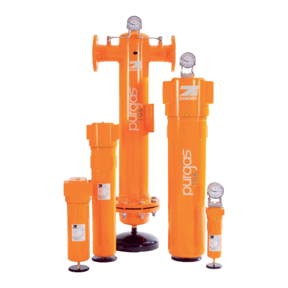
- Page 1 Microfilter for Technical Gases TGA 102-118 16-50 Bar TGH 104-118 100-420 Bar TGS 214-232 16-100 Bar TGE302-326 16-100 Bar 14/02/2022 Rev. 05 Operating Instructions cod: 398H271902...
-
Page 3: Table Of Contents
EN | Operating Instructions Index 1. General information Warranty notes ......................2 Notes on these operating instructions ..............2 2. For your own safety Intended use ......................4 Hazard areas on the fi lter ..................5 Safety notes on specifi c operating phases .............. 5 3. -
Page 4: General Information
EN | Operating Instructions General information 1. General information Warranty notes In the following cases, the warranty shall be void: ◊ If corrosion and malfunctions occur due to aggressive substances in the gas and in the environment. ◊ If the fi lter is not used in accordance with its intended use. ◊... - Page 5 EN | Operating Instructions General information Notes on handling operating instructions These operating instructions must be continuously available at the site where the fi lter is used. We recommend to prepare a copy and to keep the same in a safe and freely accessible place next to the fi lter.
-
Page 6: For Your Own Safety
EN | Operating Instructions For your own safety 2. For your own safety Note: When carrying out any work on the fi lters comply with all applicable national accident prevention regulations! Intended use A fi lter of the series described here must be exclusively used for fi ltering the gas noted on the fi lter’s type label. -
Page 7: Hazard Areas On The Fi Lter
EN | Operating Instructions For your own safety Hazard areas on the fi lter Symbol Hazard area Warning against overpressure The entire fi lter is pressurised during operation. Relieve all pressure before starting any work on the fi lter. Warning against explosive atmosphere/explosive gas Only fi lters with the appropriate ATEX code must be used in a potentially explosive environment and for fi ltering explosive gases. - Page 8 EN | Operating Instructions For your own safety Notes on fi lter operation ◊ Do not perform any unapproved conversions and modifi cations on the fi lters. Non-approved modifi cations will endanger the operational safety and may cause damage or personal injury. For ATEX-compliant fi lters: —...
-
Page 9: Assembly Drawings
EN | Operating Instructions Assembly Drawings 3. Assembly Drawings TGA 102–118, 16 bar and 25–50 bar Item Description Locking screw Upper housing Filter element O-ring Housing O-ring Threaded rod Filter element Lower housing 16 bar Manual drain HV01-TG 25, 50 bar: Manual drain EV05-TG 16 bar ATEX: Manual drain EV05-TG Optional Differential pressure gauge... - Page 10 EN | Operating Instructions Assembly Drawings TGH 104-118, 100–420 bar Item Description Locking screw O-ring Upper housing Threaded rod Filter element O-ring Filter element Housing O-ring Lower housing Double nipple Manual drain EV05-TG Optional Differential pressure gauge HZD80/50RTGS Earthing lug (only for AT- EX-compliant fi lters) TG-Filter...
- Page 11 EN | Operating Instructions Assembly Drawings TGS 214-232, 16 bar Item Description Upper housing Flat seal, housing Filter element Manual drain EV05-TG through EV08-TG Lower housing Optional Differential pressure gauge HZD80/50RTGS with connec- tion pipes Earthing lug and connection bore (only for ATEX-compliant fi lters) Condensate drain 11LD (up to —...
- Page 12 EN | Operating Instructions Assembly Drawings TGE 302-326, 16–100 bar Item Description Locking screw Upper housing Filter element Housing O-ring Lower housing Lock ring Double nipple Manual drain EV05-TG Optional Differential pressure gauge HZD80/50RTGS with con- nection pipes Earthing lug (only for AT- EX-compliant fi lters) Condensate drain 11LD —...
-
Page 13: Storing Fi Lters And Fi Lter Elements
EN | Operating Instructions Storing fi lters and fi lter elements 4. Storing fi lters and fi lter elements The storage space must meet the following conditions when the fi lter is to be stored for a longer period: ◊ The fi lter must not be stored out of doors. ◊... -
Page 14: Filter Installation
EN | Operating Instructions Filter installation 5. Filter installation The fi lters are supplied in a ready to operate condition and can be installed directly into the pipe system. To prevent transport damage, any ordered options come separately packed. These accessories must be fi tted to the fi lter before commis- sioning and in accordance with the respective instructions supplied. - Page 15 EN | Operating Instructions Filter installation ▶ The fi lter must always be fi tted vertically. ▶ Ensure that there is suffi cient space below the fi lter so it can be easily disassem- bled (see dimension D in the Technical Data). ▶...
-
Page 16: Maintenance Intervals And Work
EN | Operating Instructions Maintenance intervals and work 6. Maintenance intervals and work Hazard due to a sudden release of pressure! Never remove any parts of the fi lter, or manipulate the same in any way, for as long as the fi lter is still pressurised! A sudden escape of pressure may cause serious injuries. -
Page 17: Maintenance Tasks
EN | Operating Instructions Maintenance intervals and work Maintenance tasks Preparations Make the following preparations before performing maintenance on fi lters. ▶ When critical gases are fed: Flush the pipe section in question and the fi lter with inert gas. ▶... - Page 18 EN | Operating Instructions Maintenance intervals and work Retighten the earthing lugs on ATEX-compliant fi lters The earthing lugs on ATEX-compliant fi lters can loosen over the time. The conductivity may then be impaired. ▶ Tighten the earthing lugs every 6 months. Replacing fi...
- Page 19 EN | Operating Instructions Maintenance intervals and work ▶ Check the housing for tightness. TTGS fi lters Depending on its size, a fi lter housing can accom- modate up to 10 fi lter elements. The following description applies to a single fi lter element per housing, but equally to several ones as well.
- Page 20 EN | Operating Instructions Maintenance intervals and work TGE fi lters ▶ Make the same preparations as described in sec- tion on page 15. ▶ Open the lock ring with a hook wrench and take the lower housing out of the cap. ▶...
- Page 21 EN | Operating Instructions Maintenance intervals and work Replacing the cartridge of TGA and TGH fi lters Note on intervals: The operating conditions of cartridges with their respective fi llings are very specifi c and differ with regard to application. It is therefore impossible to recommend any fi...
- Page 22 EN | Operating Instructions Maintenance intervals and work ▶ For ATEX-compliant fi lters: Ensure conductivity, test and document it. ▶ Check the housing for tightness. Disposing of fi lter elements and cartridges The fi lter element or cartridge might be contaminated by the fi ltered substances. Heed the notes on hazardous substances for the fi ltered gas and applicable dis- posal regulations when disposing.
-
Page 23: Correcting Faults Procedure Following A Pressure Blow
EN | Operating Instructions Correcting faults 7. Correcting faults Procedure following a pressure blow Pressure blows can occur, e.g. when valves are opened suddenly. The fi lter ele- ment may still be usable following a pressure blow. But you must fi rst check it for damage. -
Page 24: Technical Information
EN | Operating Instructions Technical information 8. Technical information Note: The temperature class as per ATEX depends on the temperature of the infed gas. The TG fi lters are generally suited for any tempera- ture class because they do not feature a thermal source. Filter types TGA 102–118, 16–50 bar... - Page 25 EN | Operating Instructions Technical information TGH 104–118, 100–350 bar* Type Capacity* Connection Dimensions (mm) Weight (Kg) Element Num. m³/h G/DN x type TGH 104 G 1/4 TA 50_ TGH 106 G 3/8 TA 70_ TGH 108 G 1/2 TA 90_ TGH 110 G 3/4 11,0...
- Page 26 EN | Operating Instructions Technical information TGS 214–232, 16–100 bar Type Capacity* Connection Dimensions (mm) Weight Element Num. m³/h G/DN x type TGS 214 DN 50 31,0 1/TC 50_ TGS 216 DN 65 1180 38,0 1/TC 75_ TGS 218 DN 80 1180 42,0 1/TD 60_...
- Page 27 EN | Operating Instructions Technical information TGE 308–326, 16–100 bar Type Capacity* Connection Dimensions (mm) Weight Element Num. m³/h G/DN x type TGE 302 G 1/4 TE_09 TGE 304 G 3/8 TE_09 TGE 306 G 1/2 TE_09 TGE 308 G 3/4 TE_09 TGE 310 TE 13_...
-
Page 28: Specifi Cation Of Elements
EN | Operating Instructions Technical information Specifi cation of elements Temp. Degree of fi ltration Element Filtration effi ciency (°C) type Strainer fi lter 95 % (≥1 μm) 1–120 Coarse fi lter 99,99 % (3 μm) 1 –60 PL12 >99 % (12/25 μm) 1–120 PL25 PL12-HTCR... -
Page 29: Spare Parts And Options Spare Part Ordering
EN | Operating Instructions Spare parts and options 9. Spare parts and options Spare part ordering Please specify the correct order code (see the fi lter designation on the type label) when ordering spare parts Available options ◊ Differential pressure gauge HZD80/50RTG... and HZDE80/400RTG...* ◊... - Page 30 EN | Operating Instructions Spare parts and options TG-Filter...
- Page 32 A division of Parker Hannifi n Corporation Parker Hannifi n Manufacturing S.r.l. Sede Legale: Via Sebastiano Caboto 1, Palazzina “A” 20094 Corsico (MI) Italy Sede Operativa: Gas Separation and Filtration Division EMEA - Strada Zona Industriale, 4 35020 S.Angelo di Piove (PD) Italy tel +39 049 971 2111- fax +39 049 9701911 Web-site: www.
Need help?
Do you have a question about the TGA 102-118 and is the answer not in the manual?
Questions and answers