Table of Contents
Advertisement
Quick Links
Advertisement
Table of Contents

Related Manuals for Seco SBC-C57


Summary of Contents for Seco SBC-C57
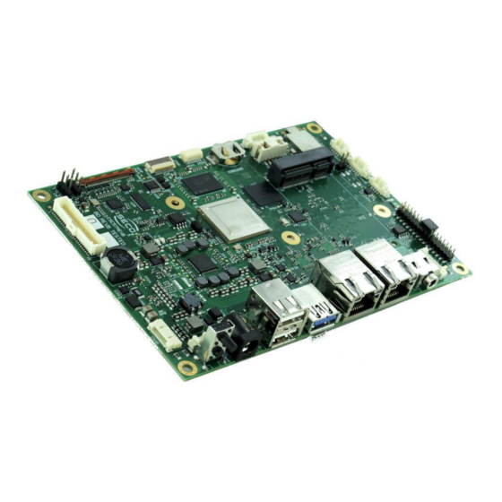
- Page 1 SBC-C57 Single Board Computer with the NXP i.MX 8X Processors on 3.5” form factor...
-
Page 2: Revision History
SECO S.p.A. reserves the right to change precise specifications without prior notice to supply the best product possible. For further information on this module or other SECO products, but also to get the required assistance for any and possible issues, please contact us using the dedicated web form available at http://www.seco.com (registration required). - Page 3 Audio Interfaces ........................................... 24 3.3.4 LVDS connector ..........................................25 3.3.5 Panel voltage selectors ........................................26 3.3.6 eDP Connector ............................................ 27 SBC-C57 SBC-C57 User Manual - Rev. First Edition: 1.0 - Author: S.O. - Reviewed by R.Z. - Copyright © 2021 SECO S.p.A.
- Page 4 Power and Reset buttons ........................................35 3.3.17 Power and Reset Connector ........................................ 35 APPENDICES ....................................36 Thermal Design ............................................37 SBC-C57 SBC-C57 User Manual - Rev. First Edition: 1.0 - Author: S.O. - Reviewed by R.Z. - Copyright © 2021 SECO S.p.A.
- Page 5 • Safety • Electrostatic discharges • RoHS compliance • Safety Policy • Terminology and definitions • Reference specifications SBC-C57 SBC-C57 User Manual - Rev. First Edition: 1.0 - Author: S.O. - Reviewed by R.Z. - Copyright © 2021 SECO S.p.A.
-
Page 6: Warranty
All changes or modifications to the equipment not explicitly approved by SECO S.p.A. could impair the equipment s functionalities and could void the warranty. SBC-C57 SBC-C57 User Manual - Rev. First Edition: 1.0 - Author: S.O. - Reviewed by R.Z. - Copyright © 2021 SECO S.p.A. -
Page 7: Information And Assistance
SECO Sales Representative: the Sales Rep can help to determine the exact cause of the problem and search for the best solution. • SECO Help-Desk: contact SECO Technical Assistance. A technician is at disposal to understand the exact origin of the problem and suggest the correct solution. -
Page 8: Electrostatic Discharges
Check carefully that all cables are correctly connected and that they are not damaged. 1.5 Electrostatic discharges The SBC-C57 board, like any other electronic product, is an electrostatic sensitive device: high voltages caused by static electricity could damage some or all the devices and/or components on-board. -
Page 9: Safety Policy
The board shall be powered by a Power Supply Unit separately approved and classified ES1/PS2 according to the requirements of IEC EN 62368-1. SBC-C57 SBC-C57 User Manual - Rev. First Edition: 1.0 - Author: S.O. - Reviewed by R.Z. - Copyright © 2021 SECO S.p.A. -
Page 10: Terminology And Definitions
Abbreviation of Physical, it is the device implementing the Physical Layer of ISO/OSI-7 model for communication systems Power Supply Unit SBC-C57 SBC-C57 User Manual - Rev. First Edition: 1.0 - Author: S.O. - Reviewed by R.Z. - Copyright © 2021 SECO S.p.A. - Page 11 User Identity Module, an extension of SIM modules. Universal Serial Bus uSDHC Ultra Secure Digital Host Controller V_REF Voltage reference Pin SBC-C57 SBC-C57 User Manual - Rev. First Edition: 1.0 - Author: S.O. - Reviewed by R.Z. - Copyright © 2021 SECO S.p.A.
-
Page 12: Reference Specifications
SM Bus http://www.smbus.org/specs USB 2.0 and USB OTG https://www.usb.org/sites/default/files/usb_20_20190524.zip Mini-PCI Express PCISIG - Mini Card Electromechanical Specification Revision 2.1 SBC-C57 SBC-C57 User Manual - Rev. First Edition: 1.0 - Author: S.O. - Reviewed by R.Z. - Copyright © 2021 SECO S.p.A. - Page 13 • Introduction • Technical specifications • Electrical specifications • Mechanical specifications • Block diagram SBC-C57 SBC-C57 User Manual - Rev. First Edition: 1.0 - Author: S.O. - Reviewed by R.Z. - Copyright © 2021 SECO S.p.A.
- Page 14 The networking capabilities of this module are extended by an optional WiFi 802.11 a/b/g/n/ac + BT 5.0 NGFF module soldered on-board. The SBC-C57 board offers two USB 2.0 and one USB 3.0 standard Type-A connectors, an internal header with an additional USB 2.0 Host port dedicated to Touch Screen driver connection, and an USB 2.0 OTG port on micro-AB connector for use in combination with Recovery mode.
-
Page 15: Technical Specifications
2 x USB 2.0 Host ports on Type-A sockets 1 x USB 3.0 Host ports on Type-A socket ** Measured at any point of SECO standard heatsink for this product, during 1 x USB 2.0 Host port header dedicated to Touch Screen driver connection any and all times (including start-up). -
Page 16: Electrical Specifications
2.3.1 Power requirement When powering SBC-C57 with a PSU with characteristics greater or equal to the one described in paragraph 2.3, please consider thoroughly the use scenario of the board (i.e., which peripherals will be connected) Since all the power must be supplied by a single external PSU, it must be cumulated the power consumption of the board itself with that of all external devices. -
Page 17: Power Rails
Stress test: Audio, Eth0, Eth1, Wifi 10.2W 0.425A 10.3W 0.429A Commercial Temperature range 15.6” eDP display type BOE EV156FHM-N10 connected SBC-C57 SBC-C57 User Manual - Rev. First Edition: 1.0 - Author: S.O. - Reviewed by R.Z. - Copyright © 2021 SECO S.p.A. -
Page 18: Mechanical Specifications
The printed circuit of the board is made of ten layers, some of them are ground planes, for disturbance rejection. SBC-C57 SBC-C57 User Manual - Rev. First Edition: 1.0 - Author: S.O. - Reviewed by R.Z. - Copyright © 2021 SECO S.p.A. -
Page 19: Block Diagram
USB Recovery Type micro-AB WiFi+BTLE u.FL Antenna M.2 1216 Connectors FACTORY ALTERNATIVES JTAG +12..+24V +12V Power Section +3.3V SBC-C57 SBC-C57 User Manual - Rev. First Edition: 1.0 - Author: S.O. - Reviewed by R.Z. - Copyright © 2021 SECO S.p.A. - Page 20 • Introduction • Connectors overview • Connectors description SBC-C57 SBC-C57 User Manual - Rev. First Edition: 1.0 - Author: S.O. - Reviewed by R.Z. - Copyright © 2021 SECO S.p.A.
- Page 21 3.1 Introduction On SBC-C57 board, there are several connectors located on the lower plane. Standard connectors are placed on the same side of PCB, so that it is possible to place them on a panel of an eventual enclosure. Please be aware that, depending on the configuration purchased, the appearance of the board could be different from the following pictures.
-
Page 22: Connectors Overview
Jumpers List Name Description Name Description Force Recovery CAN Bus Termination CN13 Display Voltage Selector CN14 Backlight Voltage Selector SBC-C57 SBC-C57 User Manual - Rev. First Edition: 1.0 - Author: S.O. - Reviewed by R.Z. - Copyright © 2021 SECO S.p.A. -
Page 23: Connectors Description
ETHx_MDI3+/ETHx_MDI3-: Ethernet Controller #x Media Dependent Interface (MDI) I/O differential pair #3. It is the fourth differential pair in Gigabit Ethernet mode (not used in 10/100Mbps modes). SBC-C57 SBC-C57 User Manual - Rev. First Edition: 1.0 - Author: S.O. - Reviewed by R.Z. - Copyright © 2021 SECO S.p.A. -
Page 24: Audio Interfaces
3.3.2 On board WiFi + BT modules The SBC-C57 board can be equipped with a Dual band (2.4GHz + 5.0 GHz) WLAN 802.11 ac/a/b/g/n + BT 5.0 embedded module, which is an AzureWave Type NGFF, p/n AW-CM276NF. This optional WiFi + BT module mounts two U.FL connectors for external antennas, where BT signal is shared with WiFi signal on the Aux antenna connector. -
Page 25: Lvds Connector
LVDS_A_CLK+ / LVDS_A_CLK-: LVDS Channel #0 differential Clock. TOUCH_SDA TOUCH_INT# LVDS_B0+ / LVDS_B0-: LVDS Channel #1 differential data pair #0. TOUCH_SDA TOUCH_SCL SBC-C57 SBC-C57 User Manual - Rev. First Edition: 1.0 - Author: S.O. - Reviewed by R.Z. - Copyright © 2021 SECO S.p.A. - Page 26 0-Ohm resistors can be mounted (factory default: not available). Please contact your local Sales rep in case you +5V_ALW need this special configuration. SBC-C57 SBC-C57 User Manual - Rev. First Edition: 1.0 - Author: S.O. - Reviewed by R.Z. - Copyright © 2021 SECO S.p.A.
-
Page 27: Edp Connector
BKLT_PWM: this signal can be used to adjust the backlight brightness in displays supporting VCC_LCD Pulse Width Modulated (PWM) regulations (LCD_PWR electrical level). SBC-C57 SBC-C57 User Manual - Rev. First Edition: 1.0 - Author: S.O. - Reviewed by R.Z. - Copyright © 2021 SECO S.p.A. - Page 28 The signals available on this connector are exactly the same available on LVDS connector CN18, for their description TOUCH_SDA please see par. 3.3.4. TOUCH_ SCL TOUCH_ RST SBC-C57 SBC-C57 User Manual - Rev. First Edition: 1.0 - Author: S.O. - Reviewed by R.Z. - Copyright © 2021 SECO S.p.A.
-
Page 29: Pin Signal
When connecting CSI cameras to CN8 connector, it is strongly recommended to use shielded cable for EMC compatibility. SBC-C57 SBC-C57 User Manual - Rev. First Edition: 1.0 - Author: S.O. - Reviewed by R.Z. - Copyright © 2021 SECO S.p.A. -
Page 30: Usb Connectors
USB_SSRX1+/USB SSRX1-: USB Super Speed Port #1 receive differential pair USB_SSTX1- USB_SSTX1+/USB SSTX1-: USB Super Speed Port #1 transmit differential pair USB_SSTX1+ SBC-C57 SBC-C57 User Manual - Rev. First Edition: 1.0 - Author: S.O. - Reviewed by R.Z. - Copyright © 2021 SECO S.p.A. - Page 31 Common mode chokes are placed on all USB differential pairs for EMI compliance. For ESD protection, on all data and voltage lines are placed clamping diodes for voltage transient suppression. SBC-C57 SBC-C57 User Manual - Rev. First Edition: 1.0 - Author: S.O. - Reviewed by R.Z. - Copyright © 2021 SECO S.p.A.
- Page 32 USB_PCIE- up resistor. USB_PCIE+ USB_PCIE- / USBPCIE+: USB Hub Downstream Port #1, differential pair +3.3V_RUN +3.3V_RUN +1V5_RUN +3V3_RUN SBC-C57 SBC-C57 User Manual - Rev. First Edition: 1.0 - Author: S.O. - Reviewed by R.Z. - Copyright © 2021 SECO S.p.A.
- Page 33 UART2_Rx: A35 debug UART port Receive signal, +3V3_RUN electrical level UART2_Rx UART2_Tx: A35 debug UART port Transmit signal, +3V3_RUN electrical level UART2_Tx SBC-C57 SBC-C57 User Manual - Rev. First Edition: 1.0 - Author: S.O. - Reviewed by R.Z. - Copyright © 2021 SECO S.p.A.
- Page 34 RS485_D+/ RS485_D-: COM Port #3 RS-485 Mode, Differential Pair PWM_2: Generic PWM output signal managed directly from the SoC, electrical level +3V3_RUN. SBC-C57 SBC-C57 User Manual - Rev. First Edition: 1.0 - Author: S.O. - Reviewed by R.Z. - Copyright © 2021 SECO S.p.A.
-
Page 35: Jtag Connector
RST_BTN: input signal, pulled high at be reset. SBC-C57 SBC-C57 User Manual - Rev. First Edition: 1.0 - Author: S.O. - Reviewed by R.Z. - Copyright © 2021 SECO S.p.A. - Page 36 • Thermal Design SBC-C57 SBC-C57 User Manual - Rev. First Edition: 1.0 - Author: S.O. - Reviewed by R.Z. - Copyright © 2021 SECO S.p.A.
-
Page 37: Thermal Design
When using SBC-C57 boards, it is necessary to consider carefully the heat generated by the module in the assembled final system, and the scenario of utilization. Until the board is used on a laboratory shelf, on free air, just for software development and system tuning, then a heatsink with integrated fan could be sufficient for board’s cooling. - Page 38 SECO S.p.A. - Via A. Grandi, 20 52100 Arezzo - ITALY Ph: +39 0575 26979 - Fax: +39 0575 350210 www.seco.com SBC-C57 SBC-C57 User Manual - Rev. First Edition: 1.0 - Author: S.O. - Reviewed by R.Z. - Copyright © 2021 SECO S.p.A.
Need help?
Do you have a question about the SBC-C57 and is the answer not in the manual?
Questions and answers