Table of Contents
Advertisement
Quick Links
®
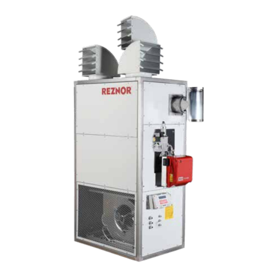
FLOOR STANDING WARM AIR HEATER
FSE Model Range (Gas & Oil)
INSTALLATION/ COMMISSIONING/SERVICING
Machinery Directive (2006/42/EC)
Low Voltage Directive (2014/35/EU)
Electromagnetic Compatibility Directive: (2014/30/EU)
Regulation (EU) 2016/2281
Gas Appliance Regulations (EU) 2016/426
Please read this document carefully before commencing installation, commissioning and/or servicing.
Leave it with the end user/site agent to be placed in their premises technical file after installation.
WARNING
Improper installation, adjustment, alteration, service or maintenance can cause property damage, injury or death.
All work must be carried out by appropriately qualified persons.
The manufacturer does not take any responsibility in the event of non-observance of the regulations concerning the connection of the apparatus
causing a dangerous operation possibly resulting in damage to the apparatus and/or environment in which the unit is installed.
Manual Part No. D301160 Issue H
Advertisement
Table of Contents

Related Manuals for Nortek Reznor FSE Series


Summary of Contents for Nortek Reznor FSE Series
- Page 1 ® FLOOR STANDING WARM AIR HEATER FSE Model Range (Gas & Oil) INSTALLATION/ COMMISSIONING/SERVICING Machinery Directive (2006/42/EC) Low Voltage Directive (2014/35/EU) Electromagnetic Compatibility Directive: (2014/30/EU) Regulation (EU) 2016/2281 Gas Appliance Regulations (EU) 2016/426 Please read this document carefully before commencing installation, commissioning and/or servicing. Leave it with the end user/site agent to be placed in their premises technical file after installation.
-
Page 3: Table Of Contents
CONTENTS INDEX General Health and Safety ..................... 1 General ..........................4 Compliance notices ........................ 5 Warranty ..........................6 Technical Data ........................8 Identification .......................... 8 Structure ..........................9 Pre installation ........................14 Handling ..........................15 Installation considerations ...................... 16 Safety area ..........................17 Air supply and return ...................... - Page 4 PRODUCT INTRODUCTION The FSE range of cabinet heaters combine innovative design with proven heat exchanger technology to provide a high efficiency cost effective and durable range. The units may be specified for either free blowing applications or for use with ductwork. Model Range+ Gas fired cabinet heaters are suitable for use with Natural Gas (G20), most units can also be specified for Propane (G31)
-
Page 5: General Health And Safety
HEALTH AND SAFETY General Health and Safety • Do not store or use petrol or other flammable vapours and liquids in the WARNING vicinity of the appliance. Warning is used when failure • In case of persisting problems, contact to heed or implement the your distributor instruction(s) can lead to not only component damage, but... - Page 6 Before using this appliance: Suitable protection should be provided for the appliance when it is located in a position where it may be susceptible • Check that the voltage indicated on to external mechanical damage; for the type plate corresponds to the mains example, fork lift trucks, overhead supply voltage.
- Page 7 Moreover, such a situation could also The main electrical supply must not compromise the safe and efficient be switched off or disconnected as a running of the appliance itself, and method for stopping the heater, the thereby constitute a hazard exception to this is in an emergency, or during servicing, where the heat All heaters must be earthed.
-
Page 8: General
GENERAL General • Turn the appliances’ electrical supply off via the local isolator. • Close the main fuel supply valve This manual is an integral part of the heater, therefore it should always be If there is a long period of time between carefully kept and it should always be operation, it is recommended that you provided together with the heater, if it is... -
Page 9: Compliance Notices
Compliance notices consequences of any operations carried out and not specifically provided for or for translations open to misinterpretation. • The heater range detailed herewith are manufactured within a strictly The electrical system must feature suitable controlled quality environment within individual and independent electrical the parameters of ISO 9001. -
Page 10: Warranty
Warranty The Warm Air Heater range conforms to the following standards: The heater is supplied with a 1 year parts and labour warranty and a further year on EN 292-1 all parts excluding consumables. Safety of Machinery - Basic Concepts, General Principles for Design Basic The warranty commences from the date Terminology Methodology... - Page 11 • Heater serial number consequential loss resulting from any failure • Order reference/date of order, together of the heater(s). with Nortek Global HVAC equipment • Full installation details (name and must be installed and maintained address Details or symptoms of fault WARNING in accordance with the •...
-
Page 12: Technical Data
TECHNICAL DATA Technical Data fans max. 60 seconds after the burner has started and stops them approx. 4 minutes after the burner has switched Heat Exchanger off. Manufactured from welded stainless steel, • “SAFETY” function (TR safety it can be easily inspected for cleaning and thermostat - factory calibration + 80°C), maintenance operations and comprises the has the function of interrupting the... -
Page 13: Structure
Fixed protection In order to avoid accidental contact with the movable parts of the machine, check if the following fixed protections have been properly installed: • Grille on air intake. • Appliance infill panels. • Burner casing. Structure Legend 1. Secondary heat exchangers 2. - Page 14 Figure 4. Dimensions and weight MODEL Net weight Flue Ø mm Flue Ø nom FSE 40 1500 5” FSE 60 1650 6” FSE 75 1650 6” FSE 100 1200 1900 7” FSE 145 1200 1900 7” FSE 175 1000 1500 2150 8”...
- Page 15 Model Flue type Class B23 / B53 Heat output (G20) 39.0 56.8 68.5 99.2 143.5 175.9 223.4 300.0 Heat input nett (G20) 43.0 63.0 75.2 110.0 158.0 195.0 248.0 328.0 Efficiency nett Gross flue gas temperature (1) °C Heat output low fire 28.0 38.2 52.9...
- Page 16 Kerosene Model Flue type Class B23 / B53 Heat output (28 sec) 40.0 57.3 69.8 102.1 138.4 182.0 210.4 305.4 Heat input nett (28 sec) 43.0 61.0 75.2 110.0 150.0 195.0 225.0 328.0 Efficiency nett Gross flue gas temperature (1) °C Heat output low fire 35.8...
- Page 17 Gas categories and emissions class Always ensure that the gas burner is certified for the correct category. The unit is certified in EU countries and countries to soon enter the EU, according to the gas categories shown Model FSE 40 FSE 60 FSE 75 FSE 100...
-
Page 18: Pre Installation
INSTALLATION Pre installation Final connections for any additional external controls must be completed on site, and must be carried out according to local and national regulations. Separate Packaging user information is provided for the time control unit and the burner, and forms The heater will usually be supplied wrapped part of the product information pack in heavy gauge polythene, non assembled... -
Page 19: Handling
Failure to adhere to these latter two points can result in the generation and transmission of excess noise. Where ducting is installed in concrete flooring a permanent membrane must be used to isolate the ducting from the Figure 5 Nozzle system corrosive effect of the alkaline salts within the concrete. -
Page 20: Installation Considerations
To properly install the heater, bear in mind that the heaters should: • Be placed on a flat surface, capable of bearing its weight; • Be supported over the entire perimeter of the lower base; • Be placed on a surface whose deflection and strength is such that it can prevent vibrations from reaching underneath;... -
Page 21: Safety Area
Blocks for transportation To prevent damage during transport, some mechanical blocks may be installed (red in colour) that constrain the movement of certain internal components. The identification and instructions for removal of these blocks are reported on a self- adhesive label positioned on the unit. Remove blocks before start-up. -
Page 22: Accessories
• After 3–4 minutes, (when the heat exchanger has completely cooled) the ventilation unit will also switch off. • The entire cycle is repeated automatically according to the required temperature setting for the room. Fuel connection The heater should be connected to the fuel supply by a qualified engineer only, complying with the relevant regulations. -
Page 23: Combustion Air
• The flue duct cannot rest on the not supplied by the manufacturer appliance. Condense disposal should be in line with any local requirements or codes of practice • The flue must reach the minimum pressure required by the current technical standards, considering “zero”... -
Page 24: Air Intake And Supply (Ducted Units Only)
Burner assembly prevent vibrations from transmitting to the air pipes, we recommend installing suitable anti-vibration joints. The installer is in charge of mounting, Check with the plant designer about electrically connecting and setting the installing a fire resistant shutter. burner. Note: The dimensions of the air inlet •... -
Page 25: Burner Position
Model FSE 40 FSE 60 FSE 75 FSE 100 FSE 145 FSE 175 FSE 225 FSE 300 Øi mm L mm Table 6 – Burner opening dimensions Burner position The burner must conform to the local standards and legislations in place. The RIELLO-burner has been designed to operate in the position shown in Figure 11, The positions shown in Figure 12, will not... - Page 26 Flue Discharge Pressure Switch The set-point of flue pressure switch is pre-adjusted and sealed at the factory. To stop the operation of the appliance in Before installation, check carefully that it case of accidental obstruction of the flue matches to the appliance on which it will be mounted.
-
Page 27: Oil Installation/Connection
Oil Installation/connection tank and oil line does not fall below the cold filter plugging point (cfpp), in the UK and with class D fuel (also referred to as gas Prolonged exposure and contact oil). The critical temperature is -4°C for this with gas oil can result in the summer grade. - Page 28 The size of the storage tank must take Where a return valve is fitted this must account of the estimated consumption be tamper proof to prevent inadvertent and any quantity price breaks offered by operation. If the valve is closed when the the oil supplier.
-
Page 29: Pipe Work And Fittings
Pressurised ring main system Note: It is advisable to check all pipe work prior to installation to ensure that there is no loose debris or scale present. This system is used to supply a number The oil feed to each heater must be fit- of units from a common storage tank. - Page 30 The return line should terminate within the oil tank at the same level as the suction Filler line; in this case a non return valve is not required. Should, however, the return line terminate over the fuel level, a non return valve is essential.
-
Page 31: Burner Technical Details
The dimension P should not exceed 4 H(m) L metres metres to avoid damage to the pump seals 8mm I.D 10mm I.D 10.0 10.0 20.0 15.0 30.0 20.0 40.0 Table 9 – Dimensions burner 225-300 Burner technical details The data and any pre-calibration at the Figure 18. - Page 32 Model FSE 40 FSE 60 FSE 75 FSE100 Propane Riello burner BS1D BS2D BS2D BS3D Head pressure mbar 4.50 9.20 3.80 7.80 6.70 10.00 2.90 6.50 Burner head position Air damper position Measured CO2 9.36 9.91 10.75 10.77 9.24 9.33 9.30 9.40 Measured CO...
- Page 33 Model FSE 145 FSE 175 FSE 225 FSE 300 Heating Oil Riello burner RG3D RG4D RG5D RL32 BLU Nozzle danfos 60° S 3.00 3.50 3.50 1.50 5.50 Pump pressure 13.7 14.4 10.9 10.9 17.5 Burner head position Air damper position 41.0 Measured CO2 12.47...
-
Page 34: Electrical Connections
Electrical connections • Respect polarity in the connection of the power supply (phase - neutral). In any case, make sure that the direction of The electric panel is pre-installed with rotation of the fans is correct. burner, control and safety thermostat of the •... - Page 35 CONTROL INTERCONNECTIONS Temperature Control (2nd Stage) Time / Temperature Control (1st Stage) Fan Only Function 240v Reznor, FSE, Installation Manual, EN 2020-02, D301160 Iss H...
-
Page 36: Control Panel
COMMISSIONING Control panel The thermal energy accumulated by the heat exchanger will be disposed of before the fan stops. TR safety thermostat The appliance is equipped with an automatic reset TR safety thermostat with the element positioned on the air supply. It has the function of stopping the burner if the air becomes overheated. - Page 37 At this point the burner is powered It is also necessary to make sure that the electrically, after the pre-purge function current absorbed by the motor does not of the combustion chamber, the flame will exceed what is indicated on the plate, begin to ignite.
-
Page 38: Starting And Stopping
without residual useful static pressure; if it is necessary to increase its performance, simply connect it to the average or maxi- mum rotation, respecting the wiring diagram positioned on the fan itself. Figure 21. Fan To change rpm of the fan, perform the following operations: •... -
Page 39: Inspections
Inspections • Open the room thermostat contact and make sure that the burner stops • Close the room thermostat contact In order to ensure that the heater works again and perform a new burner properly, some basic parameters should be ignition cycle checked. -
Page 40: Condensation Check
Indicators • Check that the fan electric absorption value does not exceed the value specified in the plate. Voltage presence indicator • Check that the air pressure switch on the burner is properly calibrated so that Placed on the electric panel, it is a green it will turn the burner off in case of an light indicator, which turns on when there insufficient flow of combustion air. -
Page 41: Maintenance
MAINTENANCE Maintenance Cleaning of gas or oil burner Maintenance checks should be made more frequently to CAUTION The burner should be cleaned by authorized appliances close to/or under personnel, only. particularly hot areas • Repairs or maintenance must be Electro-ventilator cleaning performed by a competent and qualified engineer. - Page 42 Jacket cleaning has been deposited in the front (8) and rear (9) manifolds • If necessary, use a vacuum, remove any With a wet cloth, clean all the inner and soot that has been deposited inside the outer surfaces of the jacket. Do not use combustion chamber solvents and / or abrasives products on the unit.
-
Page 43: Servicing
Servicing Do not use the main electrical isolator to turn off the heater, to CAUTION do so can cause damage to the Servicing must be carried out on a heat exchanger and combustion regular basis, the maximum chamber and thereby invalidate WARNING interval between services being the warranty. -
Page 44: Parts Lists
BURNER PARTS LIST Item / Model FSE 40 FSE 60 FSE 75 FSE 100 Gas - Two stage BS1D BS2D BS2D BS3D burner + gas train 29-99-579 29-99-571 29-99-571 29-99-572 Burner gasket 30-02-698 30-05-795 30-05-795 30-05-813 Control box 30-02-967 30-02-967 30-02-967 30-02-967 Spark electrode... - Page 45 Item / Model FSE 145 FSE 175 FSE 225 FSE 300 Probe / Photocell 30-07-839 30-07-839 30-07-839 30-12-135 Oil pump 30-07-854 30-07-854 30-08-570 30-12-732 Fire valve 28-30-102 28-30-102 28-30-102 28-30-102 Oil filter 29-15-012 29-15-012 29-15-020 29-15-020 Table 15d Parts list FSE 145-300 GENERAL PARTS LIST Qty Used per Model Part...
- Page 46 PAGE 42 Reznor, FSE, Installation Manual, EN 2020-02, D301160 Iss H...
-
Page 47: Erp Data Chart Natural Gas
ErP Data chart natural gas Information requirements for warm air heaters Commission Regulation (EU) 2018 B1 warm air heater: [NO] C2 warm air heater: [NO] C4 warm air heater: [NO] Type of fuel: Natural Gas FSE40 FSE60 FSE75 FSE100 FSE145 FSE175 FSE225 FSE300... -
Page 48: Erp Data Chart Oil
ErP Data chart propane gas Information requirements for warm air heaters Commission Regulation (EU) 2018 B1 warm air heater: [NO] C2 warm air heater: [NO] C4 warm air heater: [NO] Type of fuel: Propane Gas FSE40 FSE60 FSE75 FSE100 FSE145 FSE175 FSE225 FSE300... -
Page 49: Erp Data Chart Kerosene
ErP Data chart oil Information requirements for warm air heaters Commission Regulation (EU) 2018 B1 warm air heater: [NO] C2 warm air heater: [NO] C4 warm air heater: [NO] Type of fuel: Heating Oil FSE40 FSE60 FSE75 FSE100 FSE145 FSE175 FSE225 FSE300 Model:... - Page 50 ErP Data chart kerosene Information requirements for warm air heaters Commission Regulation (EU) 2018 B1 warm air heater: [NO] C2 warm air heater: [NO] C4 warm air heater: [NO] Type of fuel: Kerosene FSE40 FSE60 FSE75 FSE100 FSE145 FSE175 FSE225 FSE300 Model: Item:...
- Page 53 Tel 01384 489250 Fax 01384 489707 reznorsales@nortek.com www.reznor.eu Nortek Global HVAC is a registered trademark of the Nortek Global HVAC limited. Because of the continuous product innovation, Nortek Global HVAC reserves the right to change product specification without due notice.
Need help?
Do you have a question about the Reznor FSE Series and is the answer not in the manual?
Questions and answers