
Related Manuals for Home Decorators Collection YG726-NI


Summary of Contents for Home Decorators Collection YG726-NI
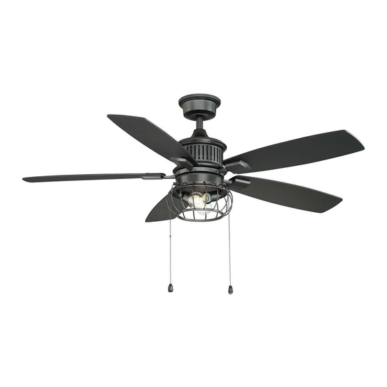
- Page 1 YG726-NI 141 643 120 V~ 60 Hz 90 W Read and follow all the instructions before using this product. Aldenshire LED Ceiling Fan Owner’s Manual Aldenshire LED Ventilador de Techo de 1,32 Manual del Propietario...
- Page 2 To ensure your combinations of wood and brass personal safety and to maximize finishes, solid designer colors, and the performance of your fan, our unique glass and crystal please read this manual designs. thoroughly. Aldenshire LED by Home Decorators Collection...
- Page 3 VENTILADOR DE TECHO/CEILING FAN Marca/Brand: Home Decorators Collection Modelo/Model: 141 643 (YG726-NI) 120 V~ 60 Hz 90 W Consumo de energía por unidad de tiempo en operación (Energy Consumption): 93.19 Wh Importador/Importer: SERVICIOS HOME DEPOT, S. DE R.L. DE C.V.
-
Page 4: Table Of Contents
Store Purchased Safety Rules ....1 141 643 (YG726-NI) UL Model No. Unpacking Your Fan ....2 Installing Your Fan . -
Page 5: Safety Rules
Safety Rules - Read and Save These Instructions To reduce the risk of electric shock, insure electricity has been turned off After making electrical connections, spliced conductors should be turned at the circuit breaker or fuse box before beginning. upward and pushed carefully up into outlet box. The wires should be spread apart with the grounded conductor and the equipment-grounding All wiring must be in accordance with the National Electrical Code conductor on one side of the outlet box and ungrounded conductor on the... -
Page 6: Unpacking Your Fan
Unpacking Your Fan Unpack your fan and check the contents. You should have the following items: Set of blades (5) Switch housing Electrical Hardware (3 Plastic Wire Nuts) Canopy assembly Light kit Ball/downrod assembly Decorative cage Coupling cover 7.5 Watt LED bulbs (2) Fan motor assembly Pull chains and fobs (2) Blade arms (5) -
Page 7: Installing Your Fan
Installing Your Fan Provide Strong Support Tools Required Figures 1~3 are examples of different ways to mount the outlet box. Phillips screwdriver, straight slot screwdriver, step ladder and wire cutters. Recessed Ceiling Outlet Box Mounting Plate Mounting Options Figure 3 Outlet Box Note: You may need a longer downrod to If there isn't an existing NOM listed mounting box,... - Page 8 Hanging the Fan Remove the ground lead from the downrod Remove the assembly. (Figure 7) Canopy Ring REMEMBER to turn off the power. Follow the NOTE: If a longer downrod is needed, take out steps below to hang your fan properly. NOTE: This ceiling fan is supplied with two types the screw located in the hanger ball, lower the hanger ball and remove the pin, remove all 3...
-
Page 9: Coupling Cover
Carefully feed the motor wires up through the downrod. Thread the downrod into the collar. Cross pin Ground Lead Align the holes and replace the clevis pin and Set Screw cotter pin. Tighten the two collar setscrews. Hanger Downrod Ball (Figure 8) Pin in Locked Motor Wires... - Page 10 Option 2: Route the wires exiting the top of the fan motor Motor through the canopy ring (make sure the slot Collar Screw and Lock Washer Close-to-Ceiling Mounting openings are on top), then proceed to place the (3 of 6 Places) canopy ring and ceiling canopy over the collar at the top of the motor.
- Page 11 Installing Fan to NOM Listed the Electrical Box Outlet Box WARNING TO REDUCE THE RISK OF FIRE, ELECTRIC Mounting SHOCK OTHER PERSONAL INJURY. Screws (Supplied MOUNT FAN ONLY TO AN OUTLET BOX OR 120V with Outlet Box) SUPPORTING SYSTEM MARKED ACCEPTABLE Groove Wires FOR FAN SUPPORT AND USE THE MOUNTING...
- Page 12 Making the Electrical Connect the fan motor black wire to the supply SUPPLY CIRCUIT black (hot) wire using a wire nut. (Figure 14) Connections Connect the blue wire for light kit to the black Ground REMEMBER to disconnect the power. household supply wire.
- Page 13 Finishing the Fan Close-to-Ceiling Mounting Outlet Box Installation Remove the fan from the hook on the mounting Screws bracket. Secure the canopy to the mounting Ceiling Standard Ceiling Mounting bracket with four screws included with your fan. Mounting (Fig. 16) Slide the canopy ring over the canopy Bracket WARNING and tighten by turning the canopy ring.
-
Page 14: Blade Arms
Attaching the Fan Blades To detach the blade from the blade arm: Press down the spring locking mechanism to release the blade from the blade arm. Slide the blade WARNING toward the blade arm until the blade disengages from the spring locking mechanism. Carefully push the blade up to detach from the blade arm. - Page 15 Attaching the Blade Assembly WARNING TO REDUCE THE RISK OF PERSONAL INJURY, DO NOT BEND THE BLADE ARMS WHILE INSTALLING, BALANCING THE BLADES, OR CLEANING THE FAN. DO NO INSERT FOREIGN OBJECTS BETWEEN ROTATING FAN BLADES. The fan motor assembly is shipped with motor support plate to prevent movement during transportation.
- Page 16 Blade Balancing All blades are grouped by weight during assembly. The following procedure should correct most fan wobble. Check after each step. Touching Ceiling Verify that all blades and blade bracket screws are secure (most fan wobble problems are caused by loose parts). Once the fan is properly installed, run the ceiling fan for 10 minutes to let the fan self-adjust.
- Page 17 Attaching the switch housing to the mounting ring WARNING BEFORE STARTING INSTALLATION, DISCONNECT THE POWER BY TURNING OFF THE CIRCUIT BREAKER OR REMOVING THE FUSE AT FUSE BOX. TURNING POWER OFF USING THE FAN SWITCH IS NOT SUFFICIENT TO PREVENT ELECTRIC SHOCK. Remove one of the three switch housing mounting screws from the mounting ring and loosen the other two screws.
-
Page 18: Installing The Light Kit
Installing the Light Kit NOTE BEFORE STARTING INSTALLATION, DISCON- NECT THE POWER BY TURNING OFF THE CIRCUIT BREAKER OR REMOVING THE FUSE AT FUSE BOX. TURNING POWER OFF USING THE FAN SWITCH IS NOT SUFFICIENT TO PREVENT ELECTRIC SHOCK. Switch Housing Remove the three light kit mounting screws from the switch housing and keep these screws. -
Page 19: Operating Your Fan
Operating Your Fan WARNING Warm weather - (Counter Clockwise Direction) A downward air flow creates a cooling effect as LOCKING SLOTS OF CEILING CANOPY ARE PRVIDED ONLY AS AN AID TO MOUNTING. DO shown in Figure 23. This allows you to set your air NOT LEAVE FAN ASSEMBLY UNATTENDED conditioner on a higher setting without affecting UNTIL ALL FOUR CANOPY SCREWS ARE... -
Page 20: Care Of Your Fan
Care of Your Fan Troubleshooting PROBLEM SOLUTION Here are some suggestions to help you maintain your fan. Fan will not start Because of the fan's natural movement, some Check main and branch circuit fuses or breakers. connections may become loose. Check the Check line wire connections to the fan and switch wire connections in support connections, brackets, and blade the switch housing. -
Page 21: Specifications
Specifications FAN SIZE SPEED VOLTS AMPS WATTS N.W. G.W. C.M. 0.23 8.4 kg 9.48 kg 0.05 52” MED. 0.45 (18.48 lbs) (20.9 lbs) HIGH 0.59 70.4 These are approximate measures. They do not include Amps and Wattage used by the light kit . Importer: SERVICIOS HOME DEPOT, S.
Need help?
Do you have a question about the YG726-NI and is the answer not in the manual?
Questions and answers