Table of Contents
Advertisement
Quick Links
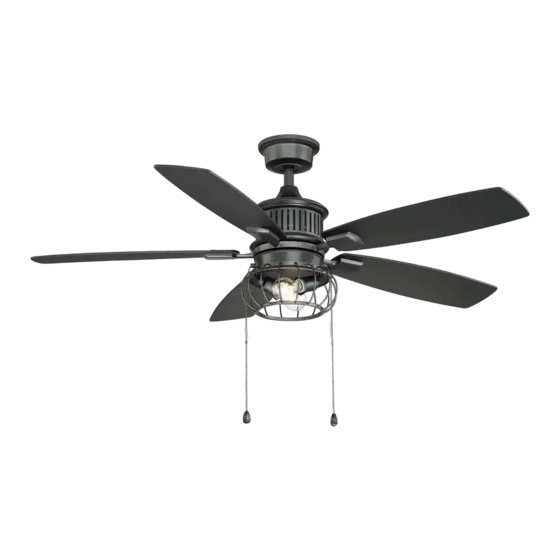
USE AND CARE GUIDE
ALDENSHIRE 52 IN. CEILING FAN
Questions, problems, missing parts? Before returning to the store,
call Home Decorators Collection Customer Service
8 a.m. - 7 p.m., EST, Monday-Friday, 9 a.m. - 6 p.m., EST Saturday
HOMEDEPOT.COM/HOMEDECORATORS
Visual instruction of how to install this fan:
Visit www.homedepot.com and enter either the Item or Model number to find
this fan and click the link of visual instruction in the product overview section.
1-800-986-3460
THANK YOU
THANK YOU
Item #1003 823 898
Model #YG726-NI
Advertisement
Table of Contents

Related Manuals for Home Decorators Collection 1003 823 898


Summary of Contents for Home Decorators Collection 1003 823 898
- Page 1 USE AND CARE GUIDE ALDENSHIRE 52 IN. CEILING FAN Questions, problems, missing parts? Before returning to the store, call Home Decorators Collection Customer Service 8 a.m. - 7 p.m., EST, Monday-Friday, 9 a.m. - 6 p.m., EST Saturday 1-800-986-3460 HOMEDEPOT.COM/HOMEDECORATORS Visual instruction of how to install this fan: Visit www.homedepot.com and enter either the Item or Model number to find...
-
Page 2: Table Of Contents
Table of Contents Table of Contents ............Operation ..............Pull Chain Operating Instructions .......... Safety Information ............Reverse Switch Operating Instructions ........Warranty ................. Care and Cleaning ............Pre-Installation .............. Troubleshooting ............Tools Required ................. Service Parts ............... Hardware Included ..............Package Contents .............. -
Page 3: Safety Information
Safety Information To reduce the risk of electric shock, ensure electricity has However, there is no guarantee that interference will not occur been turned off at the circuit breaker or fuse box before in a particular installation. If this equipment does cause harmful beginning. -
Page 4: Warranty
Warranty We warrant the fan motor to be free from defects in workmanship and material present at time of shipment from the factory for a period of lifetime after the date of purchase by the original purchaser. We also warrant that all other fan parts, excluding any glass or acrylic blades, to be free from defects in workmanship and material at the time of shipment from the factory for a period of two years after the date of purchase by the original purchaser. -
Page 5: Hardware Included
Pre-Installation (continued) HARDWARE INCLUDED HARDWARE INCLUDED NOTE: Hardware shown to actual size unless noted otherwise in the table below. Part Part Description Description Quantity Quantity Plastic wire nut Canopy mounting screw with lock washer (preassembled) Blade arm screw with lock washer (preassembled) Clevis pin (preassembled) Cotter pin (preassembled) Cross pin (preassembled) -
Page 6: Package Contents
Pre-Installation (continued) PACKAGE CONTENTS PACKAGE CONTENTS Part Part Description Description Quantity Quantity Part Part Description Description Quantity Quantity Mounting bracket (preassembled) Fan motor assembly Canopy ring (preassembled) Blade Canopy Blade arm Canopy bottom cover Switch housing Hanger ball/downrod assembly Light kit Coupling cover Decorative cage... -
Page 7: Dual Mounting Instructions
Pre-Installation (continued) DUAL MOUNTING INSTRUCTIONS DUAL MOUNTING INSTRUCTIONS This ceiling fan is supplied with two types of hanging assemblies: the standard ceiling installation using the downrod with ball and socket mounting, and the "close-to-ceiling" mounting. The "close-to-ceiling" mounting is recommended in rooms with less than 8 ft. ceilings or in areas where additional space is desired from the floor to the fan blades. -
Page 8: Installation
Installation MOUNTING OPTIONS MOUNTING OPTIONS NOTE: You may need a longer downrod to maintain proper WARNING: To reduce the risk of fire, electric shock, or blade clearance when installing on a steep, sloped ceiling. personal injury, mount the fan to an outlet box marked The maximum angle allowable is 18°... -
Page 9: Assembly
Assembly — Standard Ceiling Mounting Preparing the canopy Preparing the motor □ □ Remove the cotter pin (EE) and clevis pin (DD), and Remove the canopy ring (B) from the canopy (C). loosen the two collar setscrews (HH) from the motor collar. -
Page 10: Close-To-Ceiling Mounting
Assembly — Close-to-Ceiling Mounting Preparing the canopy Preparing the motor □ □ Remove the canopy ring (B) from the canopy (C). Remove three of the six collar mounting screws with lock washers (II) (every other one) from the collar on □... -
Page 11: Hanging The Fan
Assembly — Hanging the Fan Attaching the fan to the electrical box WARNING: To reduce the risk of fire, electric shock or other personal injury, mount the fan only to an outlet box or supporting system marked acceptable for fan support and use the mounting screws provided with the outlet box. - Page 12 Assembly — Hanging the Fan (continued) Making the electrical connections Ground Black White conductor WARNING: To avoid possible electrical shock, be sure electricity is turned off at the main fuse box before wiring. WARNING: Check to see that all connections are tight, including ground, and that no bare wire is visible at the wire nuts (except for the ground wire).
- Page 13 Assembly — Hanging the Fan (continued) Standard ceiling mounting Close-to-ceiling mounting WARNING: Locking slots of the canopy (C) are provided WARNING: Make sure the tab on the mounting bracket (A) only as an aid to mounting. Do not leave the fan assembly properly sits in the groove in the hanger ball (E) before unattended until all four canopy mounting screw (BB) are attaching the canopy (C) to the mounting bracket (A) by...
-
Page 14: Attaching The Fan Blades
Assembly — Attaching the Fan Blades Attaching the blades to the blade arms WARNING: Failure to properly seat the blades (H) on the blade arms (I) and engage in the spring locking mechanism (VV) could result in the fan blades (H) loosening and possibly falling. -
Page 15: Installing The Light Kit
Assembly — Installing the Light Kit Fastening the blade Attaching the switch housing assemblies to the motor to the mounting ring CAUTION: WARNING: To reduce the risk of personal injury, do not Before starting installation, disconnect the power by turning off the circuit breaker or removing the fuse bend the blade arms (I) while installing, balancing the blades at the fuse box. - Page 16 Assembly — Installing the Light Kit Attaching the light kit to Installing the decorative cage the switch housing □ Remove the three light kit mounting screws (KK) from the NOTE: The pull chain guide (CCC) on the decorative cage (L) switch housing (J) and keep these screws.
-
Page 17: Operation
Operation PULL CHAIN OPERATING INSTRUCTIONS PULL CHAIN OPERATING INSTRUCTIONS Install two pull chains and fobs (NN) onto the pull chains located in the switch housing (J). Turn on the power and check the operation of the fan. The pull chain controls the fan speed as follows: 1 pull - High, 2 pulls - Medium, 3 pulls - Low, and 4 pulls - Off. -
Page 18: Care And Cleaning
Care and Cleaning Do Do Do not Do not □ Check the support connections, brackets, and blade □ Use water when cleaning. Water could damage the motor, attachments twice a year. Make sure they are secure. or the wood, or possibly cause an electrical shock. Because of the fan’s natural movement, some connections may become loose over time. - Page 19 Troubleshooting (continued) Problem Problem Solution Solution □ Check that all blade and blade arm screws are secure. □ Most fan wobble problems are caused when blade levels are unequal. Check this level by selecting a point on the ceiling above the tip of one of the blades. Measure from a point on the center of each blade The fan wobbles.
-
Page 20: Service Parts
Service Parts Part Part Description Part Description Description Mounting bracket (preassembled) Plastic wire nut Canopy ring (preassembled) Canopy mounting screw with lock washer (preassembled) Canopy Blade arm screw with lock washer (preassembled) Canopy bottom cover Clevis pin (preassembled) Hanger ball/downrod assembly Cotter pin (preassembled) Coupling cover Cross pin (preassembled) - Page 21 Questions, problems, missing parts? Before returning to the store, call Home Decorators Collection Customer Service 8 a.m. - 7 p.m., EST, Monday-Friday, 9 a.m. - 6 p.m., EST Saturday 1-800-986-3460 HOMEDEPOT.COM/HOMEDECORATORS Retain this manual for future use. YG726001-A...
Need help?
Do you have a question about the 1003 823 898 and is the answer not in the manual?
Questions and answers