Sign In
Upload
Download
Table of Contents
Contents
Add to my manuals
Delete from my manuals
Share
URL of this page:
HTML Link:
Bookmark this page
Add
Manual will be automatically added to "My Manuals"
Print this page
×
Bookmark added
×
Added to my manuals
Manuals
Brands
Allen-Bradley Manuals
UPS
DC-UPS
Manual
Allen-Bradley DC-UPS Manual
Hide thumbs
1
2
Table Of Contents
3
4
5
6
7
8
9
10
11
12
13
14
15
16
17
18
19
20
21
22
23
24
25
26
27
28
29
30
31
32
33
34
35
36
37
38
39
40
page
of
40
Go
/
40
Contents
Table of Contents
Bookmarks
Table of Contents
Table of Contents
Terminology and Abbreviations
Product Overview
Specifications
Catalog Numbers
Installation Instructions
Input/Output
Batteries and Battery Charging
Buffer Time
Ready and Buffering Relay Contact
Replace Battery Relay Contact
Inhibit Input
Efficiency and Power Losses
Lifetime Expectancy and MTBF
Functional Diagram
Terminals and Wiring
Front User Elements
Electromagnetic Compatibility
Environment
Protection Features
Safety Features
Dieletric Strength
Certifications and Standards Compliance
Approximate Dimensions and Weight
Accessories
Application Notes
Additional Resources
Advertisement
Quick Links
Download this manual
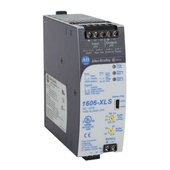
DC-UPS - 24V, 20 A, 480 W
Catalog Number 1606-XLS480-UPS
Reference Manual
Original Instructions
Table of
Contents
Previous
Page
Next
Page
1
2
3
4
5
Advertisement
Table of Contents
Need help?
Do you have a question about the DC-UPS and is the answer not in the manual?
Ask a question
Questions and answers
Related Manuals for Allen-Bradley DC-UPS
UPS Allen-Bradley Bulletin 1609 User Manual
Bulletin 1609 uninterruptible power supply (34 pages)
UPS Allen-Bradley 1606-XLS240-UPSC Reference Manual
Dc-ups with integrated battery - 24v, 10 a (34 pages)
UPS Allen-Bradley 1609-P3000N User Manual
3000/5000 va ups; tower/rack-mount 3u uninterruptible power supply (19 pages)
UPS Allen-Bradley 1609-P3000N Quick Start Manual
(49 pages)
UPS Allen-Bradley 1609 Installation Instructions Manual
Industrial uninterruptible power supply (8 pages)
UPS Allen-Bradley ControlNet PLC-5 User Manual
Hot backup system (78 pages)
UPS Allen-Bradley 1609-P8000E User Manual
8000/10000 va ups tower/rack-mount 6u uninterruptible power supply 200-240 vac (18 pages)
This manual is also suitable for:
1606-xls480-ups
Table of Contents
Print
Rename the bookmark
Delete bookmark?
Delete from my manuals?
Login
Sign In
OR
Sign in with Facebook
Sign in with Google
Upload manual
Upload from disk
Upload from URL


Need help?
Do you have a question about the DC-UPS and is the answer not in the manual?
Questions and answers