Table of Contents
Advertisement
Quick Links
Advertisement
Table of Contents

Related Manuals for Sunny Health & Fitness P8400


Summary of Contents for Sunny Health & Fitness P8400
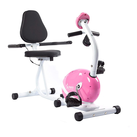
- Page 1 PINK MAGNETIC RECUMBENT BIKE P8400 USER MANUAL...
-
Page 2: Important Safety Information
IMPORTANT SAFETY INFORMATION We thank you for choosing our product. To ensure your safety and health, please use this equipment correctly. It is important to read this entire manual before assembling and using the equipment. Safe and effective use can only be achieved if the equipment is assembled, maintained, and used properly. It is your responsibility to ensure that all users of the equipment are informed of all warnings and precautions. -
Page 3: Exploded Diagram
EXPLODED DIAGRAM 1... -
Page 4: Hardware Package
EXPLODED DIAGRAM 2 HARDWARE PACKAGE #16 M10*60 4PCS #19 d10*Φ25*2*R30 4PCS #37 M8*60 1PC #7 d8*Φ20*2*R30 4PCS #8 M8*16 5PCS #32 d8*Φ16*1.5 2PCS #20 M10 4PCS #38 d8 2PCS #31 M8 1PC #46 S17-19 1PC #22 M16*1.5*27 1PC #45 S13-14-15 1PC #44 S6 1PC... -
Page 5: Parts List
PARTS LIST Description Spec. Qty. Description Spec. Qty. Computer Spanner S17-19 Computer Wire Fixing Plate t1.5*56*72 Screw M5*15 Screw M6*10*Φ12 Arc Washer d5*Φ20*1*R30 Washer d6*Φ16*1.5 Foam Grip Φ23*5*120 Bolt M6*12*S10 Handlebar Post Screw M6*8*Φ12 End Cap Φ25*16 Inertial Axle Arc Washer d8*Φ20*2*R30 Idler Connecting Rod Screw... - Page 6 ASSEMBLY INSTRUCTIONS We value your experience using Sunny Health and Fitness products. For assistance with parts or troubleshooting, please contact us at support@sunnyhealthfitness.com or 1-877-90SUNNY (877-907- 8669). STEP 1: #16 M10*60 2PCS Secure Front Stabilizer (No. 17) to Main Frame #19 d10*Φ25*2*R30 2PCS (No.
- Page 7 We value your experience using Sunny Health and Fitness products. For assistance with parts or troubleshooting, please contact us at support@sunnyhealthfitness.com or 1-877-90SUNNY (877-907- 8669). STEP 3: #42 M5*10 2PCS Remove 2 preassembled Screws (No. 42) from #45 S13-14-15 1PC the back of the Computer (No.
- Page 8 We value your experience using Sunny Health and Fitness products. For assistance with parts or troubleshooting, please contact us at support@sunnyhealthfitness.com or 1-877-90SUNNY (877-907- 8669). STEP 4: Secure the Rear Stabilizer (No. 27) to the Rear #16 M10*60 2PCS Main Frame (No. 25), with 2 Bolts (No. 16), 2 Arc #19 d10*Φ25*2*R30 2PCS #46 S17-19 1PC Washers (No.
- Page 9 We value your experience using Sunny Health and Fitness products. For assistance with parts or troubleshooting, please contact us at support@sunnyhealthfitness.com or 1-877-90SUNNY (877-907- 8669). STEP 5: #22 M16*1.5*27 1PC Connect Sensor Wire D (No. 14) with Sensor Wire E (No. 24), then secure the Rear Main Frame (No.
-
Page 10: Battery Installation And Replacement
BATTERY INSTALLATION & REPLACEMENT Battery Cover Battery BATTERY INSTALLATION 1. Take out 2 AAA batteries from computer box. 2. Press the buckle of battery cover on the back of the Computer (No. 1), then remove battery cover. 3. Install 2 AAA batteries into the battery case on the back of the Computer (No. 1). Pay attention to the battery + and –... -
Page 11: Exercise Computer
EXERCISE COMPUTER FUNCTION BUTTONS: MODE: Press to select functions. Press and hold the MODE button for 3 seconds to reset time, distance, and calories. SET: Press to set values of time, pulse, distance, and calories when not in scan mode. Press the MODE button to cycle through functions: time, distance, and calories to select desired function. -
Page 12: Specifications
SPECIFICATIONS: Auto Scan Every 6 seconds Running Time 00:00 ~ 99:59(Minute: Second) The max pick-up signal is 999.9 MILES/H (or Current Speed 9999RPM) FUNCTION Trip Distance 0.0 ~ 999.9 MILES Calories 0 ~ 9999 KCAL Total Distance 0 ~ 9999 MILES Pulse Rate 40-240BPM Battery Type...
Need help?
Do you have a question about the P8400 and is the answer not in the manual?
Questions and answers