
Subscribe to Our Youtube Channel
Related Manuals for Sunny Health & Fitness SF-B2640


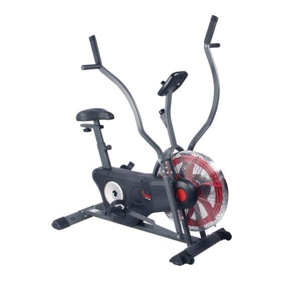
Summary of Contents for Sunny Health & Fitness SF-B2640
- Page 1 AIR BIKE TRAINER SF-B2640 USER MANUAL IMPORTANT: Read all instructions carefully before using this product. Retain owner’s manual for future reference. For customer service, please contact: support@sunnyhealthfitness.com...
-
Page 2: Important Safety Information
IMPORTANT SAFETY INFORMATION We thank you for choosing our product. To ensure your safety and health, please use this equipment correctly. It is important to read this entire manual before assembling and using the equipment. Safe and effective use can only be assured if the equipment is assembled, maintained, and used properly. - Page 3 EXPLODED DRAWING...
-
Page 4: Parts List
PARTS LIST Description Spec. Description Spec. Main Frame Outside Bearing Collar Left Handrail Arm §20*40 Bearing Washer §23.8*§40.6*T3.0 Right Handrail Arm §20*40 Bearing Snap Washer Lower Handrail Arm §20*40 Bearing Nut 7/8-24UNS □20*40*T1.5 Upright Sensor Wire □23.5*53.5*T1.5 Seat Post Sensor Holder Seat Slider Connection Wire Connection Piece... - Page 5 HARDWARE PACKAGE M6 Washer M8 Washer M10 Washer M16 Washer M14 Washer #78-2PCS #69-10PCS #77-1PCS #63-2PCS #72-4PCS M6 Arc Washer M14 Wave Washer M16 Wave Washer M6 Lock Nut #65-8PCS #95-4PCS #61-2PCS #66-4PCS Right Lock Nut Left Lock Nut M5x10 Screw M6x10 Screw #74-1PCS #75-1PCS...
- Page 6 #90 S4-1PCS #91 S5-1PCS #92 S8-1PCS #93 S13,S17,S19 -1PCS #94 S10-1PCS #22 Knob-1PCS...
-
Page 7: Assembly Instructions
ASSEMBLY INSTRUCTIONS #76 M8x35 2PCS #91 S5 1PCS STEP 1: INSTALLING UPRIGHT Lift the Upright (No.5) to the angle shown in above illustration. Make sure the 2 wires are straight and not tangled. Insert the wires into the Main Frame (No.1). - Page 8 ASSEMBLY INSTRUCTIONS #58 M5x10 4PCS #93 S13,S17,S19 1PCS STEP 2: INSTALLING THE COMPUTER Connect the Connection Wire (No.54) with the wire of Computer (No.11). Put wire into Upright (No.5), then slide the Computer (No.11) onto the plate. Secure with 4 Screws (No.58) using Combination Wrench.
- Page 9 ASSEMBLY INSTRUCTIONS #57 M8x15 4PCS #69 M8 Washer 4PCS #91 S5 1PCS STEP 3: INSTALLING THE FRONT STABLIZERS Position the Front Stabilizer (No.9) in front of Main Frame (No.1), making sure the UP label is facing up and align bolt holes. Attach the Front Stabilizer (No.9) to the Main Frame (No.1) with 4 Screws (No.
- Page 10 ASSEMBLY INSTRUCTIONS #57 M8x15 4PCS #69 M8 Washer 4PCS #91 S5 1PCS STEP 4: INSTALLING THE REAR STABLIZERS Position the Rear Stabilizer (No.10) behind the Main Frame (No.1) and align bolt holes. Attach the Rear Stabilizer (No.10) onto the Main Frame (No.1) with 4 Screws (No. 57). Tighten Screws (No.
- Page 11 ASSEMBLY INSTRUCTIONS #69 M8 Washer 2PCS #64 M6x50 4PCS #65 M6 Arc Washer 8PCS #57 M8x15 2PCS #66 M6 Lock Nut 4PCS #67 M6x10 2PCS #91 S5 1PCS #78 M6 Washer 2PCS #90 S4 1PCS #94 S10 1PCS 69 57 STEP 5: INSTALLING HANDRAILS ARM WITH LOWER HANDRAIL ARM Attach the Handrail Arm (No.2 &...
- Page 12 ASSEMBLY INSTRUCTIONS #63 M16 Washer 2PCS #59 Large Screw R 1PCS #61 M16 Wave Washer 2PCS #60 Large Screw L 1PCS #92 S8 1PCS STEP 6: INSTALLING THE LEFT & RIGHT HANDRAILS Note: Large Screw L has reverse threading and must be turned counterclockwise to tighten, as shown in above illustration.
- Page 13 ASSEMBLY INSTRUCTIONS #72 M14 Washer 4PCS #95 M14 Wave Washer 4PCS #74 Right Lock Nut 1PCS #93 S13,S17,S19 1PCS #75 Left Lock Nut 1PCS 74 18 on the right side on the left side 72 8 72 STEP 7: INSTALLING THE LEFT & RIGHT PEDALS Read this step all the way through before assembling the pedals.
- Page 14 ASSEMBLY INSTRUCTIONS #77 M10 Washer 1PCS #93 S13,S17,S19 1PCS #22 Knob 1PCS...
- Page 15 STEP 8: INSTALLING THE SEAT Unscrew Washers (No.69) and Nylon Nuts (No.71) from the Seat (No.19) using the Combination Wrench. Attach the Seat (No.19) to the Seat Slider (No.7) with Washers (No.69) and Nylon Nuts (No.71). Then attach the Seat Slider (No.7) to the Seat Post (No.6) with Knob (No.22). Insert the Seat Post (No.6) into the Main Frame (No.1) and lock it at desired height with Adjustment Knob (No.24).
- Page 16 HOW TO MOVE THE BIKE Put your hands on the Rear Stabilizer (No.10)and lift the bike until the wheels are able to move on the ground. Now you can move the bike to the desired location with ease.
-
Page 17: Specifications
EXERCISE METER SPECIFICATIONS TIME 0:00~99:59 (Minute:Second) SPEED 0~999.9 miles per hour FUNCTIONS CALORIES 0.0~999.9~9999 Kcal Distance 0.1~999.9 mile BATTERY TYPE (2)Two AAA or UM-4 OPERATING TEMPERATURE 0°C ~40°C STORAGE TEMPERATURE -10°C ~ 60°C KEY FUNCTIONS MODE: Press to select functions. Press the button and hold for two seconds to reset all functions to zero, except ODOMETER. -
Page 18: Troubleshooting
MAINTENANCE Cleaning The bike can be cleaned with a soft cloth and mild detergent. Do not use abrasives or solvents on plastic parts. Wipe your perspiration off the bike after each use. Be sure that the monitor is not exposed to excessive moisture, as this could potentially cause an electrical hazard and /or electronics to fail.
Need help?
Do you have a question about the SF-B2640 and is the answer not in the manual?
Questions and answers